EP1580461A2 - Levier de commande pour transmission automatique d'un véhicule - Google Patents
Levier de commande pour transmission automatique d'un véhicule Download PDFInfo
- Publication number
- EP1580461A2 EP1580461A2 EP05006345A EP05006345A EP1580461A2 EP 1580461 A2 EP1580461 A2 EP 1580461A2 EP 05006345 A EP05006345 A EP 05006345A EP 05006345 A EP05006345 A EP 05006345A EP 1580461 A2 EP1580461 A2 EP 1580461A2
- Authority
- EP
- European Patent Office
- Prior art keywords
- link
- selector
- select
- lever
- teeth
- Prior art date
- Legal status (The legal status is an assumption and is not a legal conclusion. Google has not performed a legal analysis and makes no representation as to the accuracy of the status listed.)
- Withdrawn
Links
Images


Classifications
-
- F—MECHANICAL ENGINEERING; LIGHTING; HEATING; WEAPONS; BLASTING
- F16—ENGINEERING ELEMENTS AND UNITS; GENERAL MEASURES FOR PRODUCING AND MAINTAINING EFFECTIVE FUNCTIONING OF MACHINES OR INSTALLATIONS; THERMAL INSULATION IN GENERAL
- F16H—GEARING
- F16H59/00—Control inputs to control units of change-speed-, or reversing-gearings for conveying rotary motion
- F16H59/02—Selector apparatus
- F16H59/08—Range selector apparatus
- F16H59/10—Range selector apparatus comprising levers
-
- F—MECHANICAL ENGINEERING; LIGHTING; HEATING; WEAPONS; BLASTING
- F16—ENGINEERING ELEMENTS AND UNITS; GENERAL MEASURES FOR PRODUCING AND MAINTAINING EFFECTIVE FUNCTIONING OF MACHINES OR INSTALLATIONS; THERMAL INSULATION IN GENERAL
- F16H—GEARING
- F16H57/00—General details of gearing
- F16H57/12—Arrangements for adjusting or for taking-up backlash not provided for elsewhere
-
- F—MECHANICAL ENGINEERING; LIGHTING; HEATING; WEAPONS; BLASTING
- F16—ENGINEERING ELEMENTS AND UNITS; GENERAL MEASURES FOR PRODUCING AND MAINTAINING EFFECTIVE FUNCTIONING OF MACHINES OR INSTALLATIONS; THERMAL INSULATION IN GENERAL
- F16H—GEARING
- F16H19/00—Gearings comprising essentially only toothed gears or friction members and not capable of conveying indefinitely-continuing rotary motion
- F16H19/001—Gearings comprising essentially only toothed gears or friction members and not capable of conveying indefinitely-continuing rotary motion for conveying reciprocating or limited rotary motion
-
- F—MECHANICAL ENGINEERING; LIGHTING; HEATING; WEAPONS; BLASTING
- F16—ENGINEERING ELEMENTS AND UNITS; GENERAL MEASURES FOR PRODUCING AND MAINTAINING EFFECTIVE FUNCTIONING OF MACHINES OR INSTALLATIONS; THERMAL INSULATION IN GENERAL
- F16H—GEARING
- F16H57/00—General details of gearing
- F16H57/12—Arrangements for adjusting or for taking-up backlash not provided for elsewhere
- F16H2057/126—Self-adjusting during operation, e.g. by a spring
- F16H2057/127—Self-adjusting during operation, e.g. by a spring using springs
-
- F—MECHANICAL ENGINEERING; LIGHTING; HEATING; WEAPONS; BLASTING
- F16—ENGINEERING ELEMENTS AND UNITS; GENERAL MEASURES FOR PRODUCING AND MAINTAINING EFFECTIVE FUNCTIONING OF MACHINES OR INSTALLATIONS; THERMAL INSULATION IN GENERAL
- F16H—GEARING
- F16H61/00—Control functions within control units of change-speed- or reversing-gearings for conveying rotary motion ; Control of exclusively fluid gearing, friction gearing, gearings with endless flexible members or other particular types of gearing
- F16H61/24—Providing feel, e.g. to enable selection
-
- F—MECHANICAL ENGINEERING; LIGHTING; HEATING; WEAPONS; BLASTING
- F16—ENGINEERING ELEMENTS AND UNITS; GENERAL MEASURES FOR PRODUCING AND MAINTAINING EFFECTIVE FUNCTIONING OF MACHINES OR INSTALLATIONS; THERMAL INSULATION IN GENERAL
- F16H—GEARING
- F16H61/00—Control functions within control units of change-speed- or reversing-gearings for conveying rotary motion ; Control of exclusively fluid gearing, friction gearing, gearings with endless flexible members or other particular types of gearing
- F16H61/26—Generation or transmission of movements for final actuating mechanisms
- F16H61/36—Generation or transmission of movements for final actuating mechanisms with at least one movement being transmitted by a cable
-
- Y—GENERAL TAGGING OF NEW TECHNOLOGICAL DEVELOPMENTS; GENERAL TAGGING OF CROSS-SECTIONAL TECHNOLOGIES SPANNING OVER SEVERAL SECTIONS OF THE IPC; TECHNICAL SUBJECTS COVERED BY FORMER USPC CROSS-REFERENCE ART COLLECTIONS [XRACs] AND DIGESTS
- Y10—TECHNICAL SUBJECTS COVERED BY FORMER USPC
- Y10T—TECHNICAL SUBJECTS COVERED BY FORMER US CLASSIFICATION
- Y10T74/00—Machine element or mechanism
- Y10T74/20—Control lever and linkage systems
- Y10T74/20012—Multiple controlled elements
- Y10T74/20018—Transmission control
- Y10T74/2003—Electrical actuator
Definitions
- the present invention relates to a selector apparatus of an automatic transmission of vehicle for carrying out the shifting operation of the transmission by transmitting the pivotal motion of the selector lever to a select-link via a gear arrangement.
- a selector apparatus having a selector lever operated by a driver is provided on a vehicle having an automatic transmission and the selector lever can be pivotally moved, for example, to a parking position (P), a reverse position (R), a neutral position (N) and a drive position (D).
- the base end of the selector lever is provided with a lever bracket which has an aperture for pivotal shaft of the selector lever and is connected to the automatic transmission via a push-pull wire.
- a lever bracket is formed with teeth of a sector gear and a select-link is also provided with a sector gear having teeth mating with that of the sector gear of the lever bracket.
- the select-link is pivotally mounted on a bracket similarly to the selector lever and connected by a push-pull wire extending to an automatic transmission.
- the transmission can be actuated by a driver operating the selector lever via the sector gear arrangement and the push-pull wire.
- an object of the present invention to provide a selector apparatus of an automatic transmission of vehicle which can suppress backlash of teeth of the gear arrangement of the lever bracket and the select-link to improve good operability of the selector lever by urging the select-link along its pivotal axis so that the teeth of the select-link are urged on to the teeth of the lever bracket.
- a selector apparatus of an automatic transmission of vehicle comprising: brackets to be secured on a body of vehicle; a selector lever pivotally supported on the brackets; a lever bracket arranged at a base end of the selector lever and formed with sector gear teeth; and a selector-link for actuating a transmission via a wire interposed between the selector-link and the transmission formed with sector gear teeth mating with the sector gear teeth of the lever bracket and rotated by the pivotal motion of the selector lever characterized in that: tooth surfaces of the teeth of the lever bracket and the select-link are tapered, and there is provided an urging means for urging the select-link along its pivotal axis so that the teeth of the select-link are urged on to the teeth of the lever bracket.
- a surface of the select-link against which the urging means abuts is formed with wavy irregularities each corresponding to one position of the selector lever.
- the urging means usually urges the select-link toward the lever bracket so that the teeth of the select-link are brought close to the teeth of the lever bracket, it is possible to suppress increase of backlash of teeth of the gear arrangement of the lever bracket and the select-link and thus to improve good operability of the selector lever. Since the teeth both of the lever bracket and the select-link are tapered, they can be urged each other by urging and thus displacing the select-link along its pivotal axis.
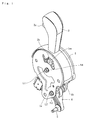
- a selector apparatus of an automatic transmission of vehicle of the present invention is a type which can select any driving position of an automatic transmission by transmitting the pivotal motion of a selector lever to a select-link via sector gears and generally comprises, as shown in Fig. 1, brackets 1a and 1b to be secured on a body of vehicle, a selector lever 2 pivotally supported within the brackets 1a and 1b, a lever bracket 3 (see Fig.2) mounted on the base end of the selector lever 2, and a select-link 4.
- the bracket 1a is formed by a metal sheet member and formed with a erroneous operation preventing window 1aa having a configuration according to positions of the selector lever 2 as well as apertures for passing therethrough shafts L1 and L2 respectively of the selector lever 2 and select link 4.
- the bracket 1a is combined to a bracket 1b to form a box structure of the selector apparatus to be mounted on a body of vehicle.
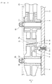
- the bracket 1b has a secured shaft L1 and a floating shaft L2 for pivotally supporting the lever bracket 3 and the select-link 4 respectively and is formed with a accommodating bore 1ba (see Fig. 3) opened toward the side of the select-link 4 and accommodated therein a detent spring 7 and a ball 8 as an urging means.
- Each end of the shafts L1 and L2 is formed with a screw thread on which nuts N1 and N2 are fastened after the lever bracket 3 and a select-link 4 etc. are assembled onto the bracket 1b via the bracket 1a.
- the selector lever 2 pivotally operated by a driver of vehicle has a push knob 2a (see Fig. 2) at its top end and is connected, at its bottom end, to the lever bracket 3 via a lever pipe (not shown).
- a rod lock pin (not shown) is arranged within the lever pipe and a lock pin 2b engaging said erroneous operation preventing window 1aa is passed through the rod lock pin and the lever bracket 3.
- the lock pin 2b engages the erroneous operation preventing window 1aa and prevent the selector lever 2 from being shifted toward the reverse position (R).
- the rod lock pin 7 is moved downward and thus the locking by the lock pin 2b is released.
- the selector lever 2 is allowed to be pivoted from the parking position (P) to the reverse position (R).
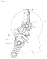
- the lever bracket 3 is arranged at the bottom end (base end) of the selector lever 2 and is able to pivot around the shaft L1 together with the selector lever 2.
- the lever bracket 3 is also formed with teeth 3a of a sector gear at a position lower than the shaft L1.
- the select-link 4 is also pivotable around the shaft L2 and also formed, at its top end, with teeth 4a of a sector gear mating with the teeth 3a of sector gear of the lever bracket 3.
- the bottom end of the select-link 4 is provided with an end bolt 5 for connecting a push-pull wire W is passed (see Figs. 2).
- the select-link 4 is formed with a through aperture 4b and is pivotably and slidably mounted on the shaft L2 and thus can slidable a slight distance along the shaft L2 as shown by an arrow "a" in Fig. 3.
- the select-link 4 is integrally formed with e.g. by insert method a slide member 9 of wear resisting material having a projected portion projected from the side of the select-link 4.
- the projected portion of the slide member 9 has a circular arc configuration viewed from its side as shown in Fig. 4 and the surface of the projected portion 9 is formed with wavy irregularities 9a each corresponding to one position of the selector lever 2.
- a reference numeral 6 in Figs. 1 and 2 denotes a selector lever cover and the cover 6 moves together with the selector lever 2 passed through an aperture 6a formed substantially at the center of the cover 6.
- the tooth surfaces of the teeth 3a and 4a respectively of the lever bracket 3 and the select-link 4 are tapered as shown in Fig. 3. That is, the teeth 3a and 4a of the lever bracket 3 and the select-link 4 form teeth of so-called a "taper-gear" and thus the tooth surface of the tooth 3a of the lever bracket 3 forms inclined surfaces in a left-right direction viewed in a sheet of Fig. 3 and the tooth surface of the tooth 4a of the select-link 4 forms counter-inclined surfaces in the same direction.
- the spring loaded ball 8 urged by the detent spring 7 is adapted to always contact and urge the wavy irregular portion 9a. Since the wavy irregular portion 9a is formed as a circular arc configuration along the pivotal locus of the select-link 4, the ball 8 can be always positioned on the wavy irregular portion 9a.
- the ball 8 fits into any one recessed portion of the wavy irregularities 9a when the selector lever 2 is positioned at any one of positions (e.g. parking, reverse or drive position etc.) and firmly holds the selector lever 2 at the selected position.
- the ball 8 rides over the peak of one wavy irregular portion 9a and then fall down the valley thereof. This provides a driver of vehicle with "shift-click feeling" during the operation of the selector lever 2.
- select-link 4 is always urged toward a direction shown by an arrow "a" in Fig. 3 by the ball 8 urged by the detent spring 7 so that the teeth 4a of the select-link 4 are urged toward the teeth 3a of the lever bracket 3.
- the ball 8 can continue to apply the urging force to the select-link 4 along the wavy irregular portion 9a.
- the select-link 4 is moved by the spring loaded ball 8 along its shaft L2 (i.e. toward a direction not giving any influence as to tension to the push-pull wire W), the play of the wire W is not increased and thus deterioration of operability of the selector apparatus can be prevented.
- urging means e.g. elastic plastic member or rib, leaf spring etc. extending from the bore 1ba to said side surface of the select-link 4
- the urging means may be provided on the bracket 1b, it may be possible to provide it on the bracket 1a. In this case, it is necessary to reverse the direction of the taper of teeth 3a and 4a.
- the position at which the urging force is applied may be anywhere of the select-link 4. However, it is preferable to set the position near the teeth 4a in order to effectively transmit the urging force to the teeth 3a and 4a.
- the present invention can be applied to those having brackets 1a and 1b or selector lever 2 of different configuration. Of course, the present invention can be also applied to a selector apparatus having any type of parking lock mechanism.
- the present invention can be applied to any selector apparatus having a different outline configuration or additional function so long as it has tapered teeth of the lever bracket and the select-link and the urging means applies the urging force to the select-link along its shaft.
Landscapes
- Engineering & Computer Science (AREA)
- General Engineering & Computer Science (AREA)
- Mechanical Engineering (AREA)
- Arrangement Or Mounting Of Control Devices For Change-Speed Gearing (AREA)
- Gear-Shifting Mechanisms (AREA)
- Control Of Transmission Device (AREA)
Applications Claiming Priority (2)
| Application Number | Priority Date | Filing Date | Title |
|---|---|---|---|
| JP2004089723A JP2005271789A (ja) | 2004-03-25 | 2004-03-25 | 車両用自動変速操作装置 |
| JP2004089723 | 2004-03-25 |
Publications (2)
| Publication Number | Publication Date |
|---|---|
| EP1580461A2 true EP1580461A2 (fr) | 2005-09-28 |
| EP1580461A3 EP1580461A3 (fr) | 2007-12-19 |
Family
ID=34858469
Family Applications (1)
| Application Number | Title | Priority Date | Filing Date |
|---|---|---|---|
| EP05006345A Withdrawn EP1580461A3 (fr) | 2004-03-25 | 2005-03-23 | Levier de commande pour transmission automatique d'un véhicule |
Country Status (3)
| Country | Link |
|---|---|
| US (1) | US20050217403A1 (fr) |
| EP (1) | EP1580461A3 (fr) |
| JP (1) | JP2005271789A (fr) |
Families Citing this family (3)
| Publication number | Priority date | Publication date | Assignee | Title |
|---|---|---|---|---|
| JP2005273819A (ja) * | 2004-03-25 | 2005-10-06 | Atsumi Tec:Kk | 車両用自動変速操作装置 |
| CN104214325B (zh) * | 2013-05-30 | 2016-12-28 | 崴立机电(苏州)有限公司 | 双齿错齿齿隙控制装置 |
| KR20220151186A (ko) | 2020-04-01 | 2022-11-14 | 가부시키가이샤 아쯔미테크 | 차량용 변속기의 조작 장치 및 차량 |
Citations (1)
| Publication number | Priority date | Publication date | Assignee | Title |
|---|---|---|---|---|
| JPH07315070A (ja) | 1993-02-18 | 1995-12-05 | Ford Motor Co | 自動変速機のギヤセレクター組立体 |
Family Cites Families (6)
| Publication number | Priority date | Publication date | Assignee | Title |
|---|---|---|---|---|
| US835210A (en) * | 1905-10-03 | 1906-11-06 | Bernhard Beskow | Controlling device for speed-changing mechanisms. |
| FR523318A (fr) * | 1919-10-04 | 1921-08-17 | Anciens Etablissements Secquev | Dispositif de changement de vitesse pour véhicule automobile |
| DE649573C (de) * | 1934-11-25 | 1937-08-27 | Auto Union A G | Schaltvorrichtung fuer Zahnraederwechselgetriebe, insbesondere von Kraftfahrzeugen |
| US2529741A (en) * | 1948-08-16 | 1950-11-14 | Glyn P Roberts | Control mechanism for epicyclic gearboxes |
| DE19924791C1 (de) * | 1999-05-29 | 2001-02-08 | Deere & Co | Schaltvorrichtung für Kraftfahrzeuggetriebe |
| FR2803252B1 (fr) * | 1999-12-29 | 2002-03-22 | Renault | Dispositif de commande de boite de vitesses manuelle |
-
2004
- 2004-03-25 JP JP2004089723A patent/JP2005271789A/ja active Pending
-
2005
- 2005-03-23 EP EP05006345A patent/EP1580461A3/fr not_active Withdrawn
- 2005-03-25 US US11/090,860 patent/US20050217403A1/en not_active Abandoned
Patent Citations (1)
| Publication number | Priority date | Publication date | Assignee | Title |
|---|---|---|---|---|
| JPH07315070A (ja) | 1993-02-18 | 1995-12-05 | Ford Motor Co | 自動変速機のギヤセレクター組立体 |
Also Published As
| Publication number | Publication date |
|---|---|
| EP1580461A3 (fr) | 2007-12-19 |
| JP2005271789A (ja) | 2005-10-06 |
| US20050217403A1 (en) | 2005-10-06 |
Similar Documents
| Publication | Publication Date | Title |
|---|---|---|
| US8024990B2 (en) | Shift lever apparatus | |
| EP2261535B1 (fr) | Dispositif de changement de mode pour transmission automatique | |
| US4328712A (en) | Lockout for gimbal-type automotive transmission gear shifter | |
| JP2003127691A (ja) | 多段自動変速機操作装置 | |
| JP4205372B2 (ja) | 自動変速機のセレクトシステム | |
| JP5530582B2 (ja) | シフトロック組立体 | |
| EP1580462A2 (fr) | Levier de commande pour transmission automatique d'un véhicule | |
| EP1580460A2 (fr) | Levier de commande pour transmission automatique d'un véhicule | |
| US20060272441A1 (en) | Vehicular shift lock device | |
| EP1580461A2 (fr) | Levier de commande pour transmission automatique d'un véhicule | |
| US20030154813A1 (en) | Shift biased detent profile | |
| JP2004034830A (ja) | 車両用自動変速機のシフト装置 | |
| JP4888006B2 (ja) | 自動変速機の変速操作装置 | |
| AU2006252188B2 (en) | Shift lever device | |
| JP4431352B2 (ja) | 車両用変速操作装置 | |
| JP2003146102A (ja) | 車両用自動変速機のシフト装置 | |
| JP4723917B2 (ja) | 車両用シフトレバー装置 | |
| JP3987622B2 (ja) | 自動変速機の変速操作入力装置 | |
| KR100439985B1 (ko) | 수동변속기의 변속조작장치 | |
| JP7068237B2 (ja) | 車両用シフト装置 | |
| KR100578758B1 (ko) | 수동변속기의 변속조작기구 | |
| KR100391946B1 (ko) | 매뉴얼 레버 소음 방지 구조 | |
| JP5380367B2 (ja) | シフトレバー装置 | |
| JPH10309955A (ja) | 自動変速装置の変速操作装置 | |
| KR20240006837A (ko) | 차량용 파킹 장치 |
Legal Events
| Date | Code | Title | Description |
|---|---|---|---|
| PUAI | Public reference made under article 153(3) epc to a published international application that has entered the european phase |
Free format text: ORIGINAL CODE: 0009012 |
|
| AK | Designated contracting states |
Kind code of ref document: A2 Designated state(s): AT BE BG CH CY CZ DE DK EE ES FI FR GB GR HU IE IS IT LI LT LU MC NL PL PT RO SE SI SK TR |
|
| AX | Request for extension of the european patent |
Extension state: AL BA HR LV MK YU |
|
| PUAL | Search report despatched |
Free format text: ORIGINAL CODE: 0009013 |
|
| AK | Designated contracting states |
Kind code of ref document: A3 Designated state(s): AT BE BG CH CY CZ DE DK EE ES FI FR GB GR HU IE IS IT LI LT LU MC NL PL PT RO SE SI SK TR |
|
| AX | Request for extension of the european patent |
Extension state: AL BA HR LV MK YU |
|
| RIC1 | Information provided on ipc code assigned before grant |
Ipc: F16H 57/12 20060101ALN20071109BHEP Ipc: F16H 19/00 20060101ALN20071109BHEP Ipc: F16H 61/36 20060101ALN20071109BHEP Ipc: F16H 61/24 20060101ALN20071109BHEP Ipc: F16H 59/10 20060101ALI20071109BHEP Ipc: F16H 61/26 20060101AFI20071109BHEP |
|
| 17P | Request for examination filed |
Effective date: 20080613 |
|
| AKX | Designation fees paid |
Designated state(s): DE GB |
|
| GRAP | Despatch of communication of intention to grant a patent |
Free format text: ORIGINAL CODE: EPIDOSNIGR1 |
|
| STAA | Information on the status of an ep patent application or granted ep patent |
Free format text: STATUS: THE APPLICATION IS DEEMED TO BE WITHDRAWN |
|
| 18D | Application deemed to be withdrawn |
Effective date: 20090217 |