EP1580453B1 - Tooth shear resistant power transmission belt - Google Patents
Tooth shear resistant power transmission belt Download PDFInfo
- Publication number
- EP1580453B1 EP1580453B1 EP05102199A EP05102199A EP1580453B1 EP 1580453 B1 EP1580453 B1 EP 1580453B1 EP 05102199 A EP05102199 A EP 05102199A EP 05102199 A EP05102199 A EP 05102199A EP 1580453 B1 EP1580453 B1 EP 1580453B1
- Authority
- EP
- European Patent Office
- Prior art keywords
- cord
- belt
- tensile
- tooth
- teeth
- Prior art date
- Legal status (The legal status is an assumption and is not a legal conclusion. Google has not performed a legal analysis and makes no representation as to the accuracy of the status listed.)
- Ceased
Links
- 230000005540 biological transmission Effects 0.000 title description 3
- 230000002787 reinforcement Effects 0.000 claims description 34
- 239000013536 elastomeric material Substances 0.000 claims description 4
- 239000004744 fabric Substances 0.000 description 18
- 229920001971 elastomer Polymers 0.000 description 7
- 239000000806 elastomer Substances 0.000 description 7
- 229920000642 polymer Polymers 0.000 description 7
- 238000010008 shearing Methods 0.000 description 5
- 230000003014 reinforcing effect Effects 0.000 description 4
- 229920000049 Carbon (fiber) Polymers 0.000 description 3
- 229910000831 Steel Inorganic materials 0.000 description 3
- 239000004760 aramid Substances 0.000 description 3
- 229920006231 aramid fiber Polymers 0.000 description 3
- 239000004917 carbon fiber Substances 0.000 description 3
- 239000011521 glass Substances 0.000 description 3
- 239000000463 material Substances 0.000 description 3
- VNWKTOKETHGBQD-UHFFFAOYSA-N methane Chemical compound C VNWKTOKETHGBQD-UHFFFAOYSA-N 0.000 description 3
- 229920001084 poly(chloroprene) Polymers 0.000 description 3
- 239000010959 steel Substances 0.000 description 3
- 230000001360 synchronised effect Effects 0.000 description 3
- JOYRKODLDBILNP-UHFFFAOYSA-N Ethyl urethane Chemical compound CCOC(N)=O JOYRKODLDBILNP-UHFFFAOYSA-N 0.000 description 2
- 238000005299 abrasion Methods 0.000 description 2
- 239000000853 adhesive Substances 0.000 description 2
- 230000001070 adhesive effect Effects 0.000 description 2
- 238000010276 construction Methods 0.000 description 2
- 229920006168 hydrated nitrile rubber Polymers 0.000 description 2
- 229920000459 Nitrile rubber Polymers 0.000 description 1
- 239000004677 Nylon Substances 0.000 description 1
- -1 but not limited to Substances 0.000 description 1
- 230000000295 complement effect Effects 0.000 description 1
- 230000007812 deficiency Effects 0.000 description 1
- 230000001419 dependent effect Effects 0.000 description 1
- 229920001778 nylon Polymers 0.000 description 1
- 229920002635 polyurethane Polymers 0.000 description 1
- 239000004814 polyurethane Substances 0.000 description 1
- 229920002725 thermoplastic elastomer Polymers 0.000 description 1
- 229920001187 thermosetting polymer Polymers 0.000 description 1
Images


Classifications
-
- F—MECHANICAL ENGINEERING; LIGHTING; HEATING; WEAPONS; BLASTING
- F16—ENGINEERING ELEMENTS AND UNITS; GENERAL MEASURES FOR PRODUCING AND MAINTAINING EFFECTIVE FUNCTIONING OF MACHINES OR INSTALLATIONS; THERMAL INSULATION IN GENERAL
- F16G—BELTS, CABLES, OR ROPES, PREDOMINANTLY USED FOR DRIVING PURPOSES; CHAINS; FITTINGS PREDOMINANTLY USED THEREFOR
- F16G1/00—Driving-belts
- F16G1/28—Driving-belts with a contact surface of special shape, e.g. toothed
-
- F—MECHANICAL ENGINEERING; LIGHTING; HEATING; WEAPONS; BLASTING
- F16—ENGINEERING ELEMENTS AND UNITS; GENERAL MEASURES FOR PRODUCING AND MAINTAINING EFFECTIVE FUNCTIONING OF MACHINES OR INSTALLATIONS; THERMAL INSULATION IN GENERAL
- F16G—BELTS, CABLES, OR ROPES, PREDOMINANTLY USED FOR DRIVING PURPOSES; CHAINS; FITTINGS PREDOMINANTLY USED THEREFOR
- F16G1/00—Driving-belts
- F16G1/06—Driving-belts made of rubber
- F16G1/08—Driving-belts made of rubber with reinforcement bonded by the rubber
-
- F—MECHANICAL ENGINEERING; LIGHTING; HEATING; WEAPONS; BLASTING
- F16—ENGINEERING ELEMENTS AND UNITS; GENERAL MEASURES FOR PRODUCING AND MAINTAINING EFFECTIVE FUNCTIONING OF MACHINES OR INSTALLATIONS; THERMAL INSULATION IN GENERAL
- F16G—BELTS, CABLES, OR ROPES, PREDOMINANTLY USED FOR DRIVING PURPOSES; CHAINS; FITTINGS PREDOMINANTLY USED THEREFOR
- F16G1/00—Driving-belts
- F16G1/14—Driving-belts made of plastics
- F16G1/16—Driving-belts made of plastics with reinforcement bonded by the plastic material
Definitions
- the invention relates to belts like synchronous drive belts and, more specifically, to drive belts having tooth shear resistant construction.
- Positive drive belts also called interchangeably “synchronous” or “timing belts” are well known and in common usage.
- Such belts are generally made of a resilient elastomer and are reinforced with a longitudinal tensile member that lies along the pitch line of the belt and is made up of a plurality of cords of a high elastic modulus.
- the cords may be made from glass, steel, aramid or carbon fiber in order to support the tensile loads in the belt.
- the belt includes spaced-apart teeth formed of neoprene, HNBR, urethane, polychloroprene, polyurethane, NBR, or other thermoset or thermoplastic elastomers available to the industry.
- the tooth surface may be reinforced with an abrasion resistant fabric such as nylon that resists abrasion and helps resist shearing off of the tooth from the cord under load.
- belts of the conventional construction described above remain susceptible to damage or tooth breakage from shear forces when subjected to high loads as part of a duty cycle or during misuse.
- a power transmission belt is known with a reinforcement cord 3 extending along a single tensile cord 2 in a longitudinal direction of the belt.
- a power transmission belt is known with a reinforcement cord 4 looped around several tensile cords 3 in a direction transverse to the length of the belt.
- the industry remains in need of a belt configuration that is resistant to tooth shear.
- the belt will be resistant to tooth shear failure and also have a soft mode of failure wherein the teeth remain loosely attached to the cord in a position that permits belt operation even if cracked or sheared off.
- Such a belt should further resist tooth shear damage resulting from temporary high loads that can occur during part of the duty cycle or during misuse.
- a belt configuration is needed within the industry that overcomes belt failure due to tooth shear in a cost effective, dependable manner.
- the invention according to claim 1 overcomes the deficiencies in conventional belt configurations and satisfies the needs of the industry in providing a belt structure that resists tooth shear damage and provides a soft mode of failure where the teeth remain attached to the belt tensile cord even if cracked or sheared off.
- the belt includes a spiral cord (also referred to interchangeably as a "stuffer" cord) or cords that is wrapped around one or more of the tensile cords of the belt.
- the path of the stuffer cord in such a configuration is substantially a helix that follows the helix of the tensile cord.
- a portion of the stuffer cord passes over the tensile cord forming a repeating angled pattern.
- Another portion of the stuffer cord passes under the tensile cord forming a loop that is molded into each tooth of the belt.
- the spiral cord thus carries the tooth shearing loads and prevents the tooth load from damaging the face fabric and polymer of the tooth, thereby preventing the tooth from breaking off. It also prevents the tooth or teeth from separating from the cord when high loads exceed the tear strength of the tooth polymer or the adhesion of the tooth or teeth to the cord. In supporting the tooth against tooth shear forces, the spiral cord allows a lower cost face fabric and polymer to be used for a given level of performance.
- the belt teeth are locked to the tensile cord by a zigzag stuffer cord that passes alternatively over the tensile cord in opposite directions and into the teeth.
- the stuffer cord follows generally along the path of the tensile cord, passing over the cord while above a tooth space and passing between the tensile cords alternately on the left and right sides of the tensile cord down into the belt tooth.
- the zigzag cord also carries the tooth shearing loads and prevents the tooth load from damaging the face fabric and polymer of the tooth, thereby preventing the tooth from breaking off.
- a representative positive drive belt 10 is shown of a type in use within the industry.
- the belt 10 is referred interchangeably herein as a "positive drive”, “PD”, “synchronous”, or “timing” belt.
- the components of the belt 10 include a face fabric 12 that follows the profile of a plurality of spaced apart belt teeth 14.
- a plurality of spaced apart, longitudinally extending tensile cords 16 extend along the belt and elastomeric material 18 (shown semi-transparent for illustration) is provided that fills in the teeth and encapsulates the tensile cords.
- the tensile cords 16 compose the tensile cords 16 from glass, steel, aramid or carbon fiber that support the tensile loads in the belt. Other materials may be substituted if desired without departing from the invention.
- the tensile cords 16 each may be formed from a single cord strand or consist of a plurality of cord strands if desired.
- the elastomeric material 18 of the belt may be made of neoprene, HNBR, urethane or other known elastomer.
- the face fabric 12 resists abrasive wear and helps resist shearing off of the teeth from the cord under load.
- the face fabric 12 is bonded to the elastomeric material which in turn is bonded to the cord and may, accordingly, become detached when subjected to repeated loads of sufficient magnitude.
- the durability of the face fabric, and its effectiveness in resisting tooth shear, therefore, is dependent upon the efficacy of the adhesives used to bond the fabric and the tensile cord and the shear strength of the elastomer near the cord.
- FIG. 4 shows a typical PD belt 10 spanning between two drive pulleys 1, 2, each having, respectively, a series of teeth 3, 4 spaced and configured to mesh with the teeth 14 of the belt 10.
- a typical PD belt 10 spanning between two drive pulleys 1, 2, each having, respectively, a series of teeth 3, 4 spaced and configured to mesh with the teeth 14 of the belt 10.
- Such a system is useful in myriad applications such as industrial and automotive uses.
- the belt 10 ideally will resist temporary high loads that can occur during part of a duty cycle or during misuse of the belt drive system.
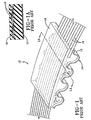
- a preferred embodiment of the present invention is manifest in a toothed belt 20 having face fabric 22, teeth 24, tensile cords 26, and elastomer 28 arranged and composed as in prior art belts described previously. Additionally, a spiral cord 30 is integrated into the belt. Spiral cord 30 is interchangeably referred to herein as a "reinforcement”, "zigzag” or “stuffer” cord. Cord 30 may be a single cord or a bundled plurality of cords composed of any conventionally available material, such as, but not limited to, glass, steel, aramid or carbon fiber.
- cord 30 may comprise a plurality of cords if desired.
- the spiral cord 30 is a reinforcement that follows along the path of a tensile cord 26, passing over the cord 26 while above a tooth space and looping down into a belt tooth to secure the tooth to the tensile cord.
- two adjacent overlay portions 32A 32B, 32 pass over the tensile cord 26 in a common direction in one embodiment, with loop portion 34 disposed therebetween.
- the path of the reinforcement cord 30 is a helix with a central axis that follows the helix of the tensile cord.
- the radius of the reinforcement cord from the helix axis varies as required to form the loop 34. It is small where the spiral cord 30 passes over the tensile cord and large where the loop passes through the tooth. While it is preferred that at least one reinforcement cord couple to each tensile cord along the belt, such is not a necessity for the practice of the invention. Some tensile cords may not have a reinforcement cord associated therewith while others may have a plurality of reinforcement cords wrapped therearound if desired for a particular application. Furthermore, the loop 34 may be formed around two or more tensile cords.
- the spiral cord loop 34 extends down into a tooth and ties the tooth into the tensile cord 26.
- the spiral cord thus carries the tooth shearing loads and prevents the tooth load from damaging the face fabric and polymer of the tooth, thereby preventing the tooth from breaking off. It also prevents the tooth, or a group of teeth, from separating from the cord when high loads exceed the tear strength of the tooth polymer or the adhesion to the cord.
- the spiral cord will support the tooth shear forces, allowing lower cost face fabric and polymer to be used at a given level of performance.
- the spacing between overlay portions and loop portions of the reinforcement cord complement the spacing between the teeth of the belt.
- the spacing is such as to provide that a loop portion of the reinforcement cord will extend down into each tooth along the belt and an overlay portion of the reinforcement cord is disposed at each gap between adjacent teeth along the belt.
- the loop 34 may extend to the bottom of the tooth. It may also extend only partly into the tooth. Other combinations are also possible.
- the portion of the reinforcement cord passing above the tensile cord may be extended along the belt so that the spiral or zigzag loops are formed only in every second, or third, or fourth tooth.
- the zigzag pattern can be made to form loops in the tooth and loops which pass between and above the tensile cords without crossing over them.
- Other configurations may also be envisioned by those skilled in the art without departing from the invention.
- the reinforcing cord 30 acts to maintain an association of the severed teeth with the belt in a soft mode of failure in which the belt is less likely to be forced off of the pulleys.
- the numeral 30 is used to describe both the spiral reinforcing cord in FIG 2B and the zigzag reinforcing cord in FIG 3B . Hence, this statement applies to both). This will allow a limited period of belt operation until the belt may be repaired or replaced.
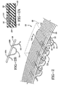
- FIGS. 3, 3A, and 3B illustrate an alternatively configured belt configured pursuant to the invention.
- the stuffer cord 30 follows along the path of the tensile cord, passing over the cord while above a tooth space and passing alternately on the left and right sides of the cord down as a loop into the belt tooth to secure it to the tensile cord.
- two overlay portions 32A and 32B in the alternate embodiment extend over the tensile cord 26 in opposite directions, with the loop portion 34 disposed therebetween.
- Such a configuration may be referred to as a "zigzag" pattern.
- Other patterns may also be deployed.
- the reinforcement cord 30 may be configured as a braided stuffer cord which includes interlocked left and right hand cord helices.
- the subject belt of the invention satisfies the need of the industry for a highly durable belt capable of operating in a soft failure mode.
- the belt resists the occurrence of tooth shear and acts by means of the reinforcement cord 30 to tie each tooth into the tensile cords 26.
- An integrated belt of superior strength and performance results.
- the high structural integrity achieved by the presence of the reinforcement cord 30 allows for a use of less expensive materials in the tooth stock as well as the face fabric.
Landscapes
- Engineering & Computer Science (AREA)
- General Engineering & Computer Science (AREA)
- Mechanical Engineering (AREA)
- Ropes Or Cables (AREA)
- Devices For Conveying Motion By Means Of Endless Flexible Members (AREA)
- Belt Conveyors (AREA)
Applications Claiming Priority (2)
| Application Number | Priority Date | Filing Date | Title |
|---|---|---|---|
| US811254 | 1977-06-29 | ||
| US10/811,254 US7217210B2 (en) | 2004-03-26 | 2004-03-26 | Tooth shear resistant power transmission belt |
Publications (3)
| Publication Number | Publication Date |
|---|---|
| EP1580453A2 EP1580453A2 (en) | 2005-09-28 |
| EP1580453A3 EP1580453A3 (en) | 2007-12-05 |
| EP1580453B1 true EP1580453B1 (en) | 2010-07-07 |
Family
ID=34862123
Family Applications (1)
| Application Number | Title | Priority Date | Filing Date |
|---|---|---|---|
| EP05102199A Ceased EP1580453B1 (en) | 2004-03-26 | 2005-03-18 | Tooth shear resistant power transmission belt |
Country Status (6)
| Country | Link |
|---|---|
| US (1) | US7217210B2 (enExample) |
| EP (1) | EP1580453B1 (enExample) |
| JP (1) | JP2005282858A (enExample) |
| CN (1) | CN1316181C (enExample) |
| BR (1) | BRPI0500991A (enExample) |
| DE (1) | DE602005022138D1 (enExample) |
Families Citing this family (13)
| Publication number | Priority date | Publication date | Assignee | Title |
|---|---|---|---|---|
| RU2402705C1 (ru) * | 2009-04-14 | 2010-10-27 | Федеральное государственное унитарное предприятие "Всероссийский научно-исследовательский институт автоматики им. Н.Л. Духова" (ФГУП "ВНИИА") | Зубчатый ремень |
| ES2682205T3 (es) | 2010-05-13 | 2018-09-19 | Otis Elevator Company | Método de fabricación de una tela tejida que tiene una separación deseada entre miembros de tensión |
| JP5091276B2 (ja) * | 2010-05-26 | 2012-12-05 | トヨタ自動車株式会社 | 歯付ベルトとその製造方法 |
| US9341232B2 (en) * | 2013-11-08 | 2016-05-17 | Gates Corporation | Two-component cord and method for molded power transmission belts |
| DE102014202967B4 (de) | 2014-02-18 | 2022-09-29 | Contitech Antriebssysteme Gmbh | Zahnriemen mit schlaufenförmig angeordneten Zugsträngen |
| DE102014221979B4 (de) * | 2014-10-28 | 2025-08-14 | Contitech Antriebssysteme Gmbh | Zahnriemen sowie Verfahren und Vorrichtung zur Herstellung desselben |
| WO2017155943A1 (en) * | 2016-03-09 | 2017-09-14 | Otis Elevator Company | Reinforced fabric elevator belt with improved internal wear resistance |
| US10012291B2 (en) * | 2016-07-21 | 2018-07-03 | Contitech Antriebssysteme Gmbh | Low modulus belt utilizing tensile member and belt carcass |
| US10514083B2 (en) * | 2016-08-16 | 2019-12-24 | Contitech Antriebssysteme Gmbh | Cross-linked elastomeric low friction faced synchronous power transmission belt |
| US11293518B2 (en) * | 2017-04-24 | 2022-04-05 | Mitsuboshi Belting Ltd. | Toothed belt |
| WO2019018068A1 (en) * | 2017-07-19 | 2019-01-24 | The Timken Company | ELECTROCONDUCTIVE BELT |
| US10882719B2 (en) * | 2018-03-29 | 2021-01-05 | Thyssenkrupp Elevator Ag | Composite elevator belt |
| EP4075018A4 (en) * | 2019-12-13 | 2023-12-20 | Mitsuboshi Belting Ltd. | TOOTHED V-BELT |
Family Cites Families (26)
| Publication number | Priority date | Publication date | Assignee | Title |
|---|---|---|---|---|
| DE533398C (de) * | 1931-09-11 | Friedrich Luthner | Treibriemen mit Zaehnen aus gummiertem Gewebe mit Metalleinlagen | |
| DE1047545B (de) * | 1956-08-29 | 1958-12-24 | Continental Gummi Werke Ag | Aus giess- oder spritzfaehigem elastischem Werkstoff bestehendes Zugglied, z. B. Treibriemen, mit eingebetteten Festigkeitstraegern |
| FR1285945A (fr) | 1961-01-13 | 1962-03-02 | Kleber Colombes | Bande transporteuse |
| US3083582A (en) * | 1961-01-17 | 1963-04-02 | Thomas E Fisher | Composite belt drive |
| GB962956A (en) * | 1962-09-15 | 1964-07-08 | Austin Motor Co Ltd | Toothed driving belts |
| GB1240123A (en) | 1967-11-15 | 1971-07-21 | Btr Industries Ltd | Improvements in conveyor belting |
| US3941162A (en) * | 1974-03-28 | 1976-03-02 | Uniroyal Inc. | Reinforcing fabric for belts |
| DE2425465B1 (de) | 1974-05-27 | 1975-03-27 | Clouth Gummiwerke Ag | Foerdergurt |
| DE2520943A1 (de) | 1975-05-10 | 1976-11-18 | Continental Gummi Werke Ag | Foerdergurt |
| DE2532190C2 (de) | 1975-07-18 | 1986-10-02 | Phoenix Ag, 2100 Hamburg | Förderband mit Stahlseileinlage |
| DE2557025A1 (de) | 1975-12-18 | 1977-06-23 | Continental Gummi Werke Ag | Foerdergurt |
| US4395298A (en) | 1980-11-10 | 1983-07-26 | Dayco Corporation | Method and apparatus for making toothed belts and belt made employing same |
| US4526637A (en) * | 1982-01-29 | 1985-07-02 | The Goodyear Tire & Rubber Company | Method of making conveyor belt |
| US4701154A (en) * | 1985-04-18 | 1987-10-20 | National Standard Company | Reinforced belt assembly and method of manufacture |
| SU1366744A1 (ru) * | 1986-07-25 | 1988-01-15 | Белорусский Политехнический Институт | Приводной ремень |
| JPS63137149U (enExample) * | 1987-02-28 | 1988-09-09 | ||
| EP0298459A3 (en) * | 1987-07-10 | 1989-05-31 | Aisin Seiki Kabushiki Kaisha | A belt |
| US5134006A (en) * | 1991-12-05 | 1992-07-28 | The Goodyear Tire & Rubber Company | Belt reinforcing fabric and a belt reinforced with the same |
| FR2685747B1 (fr) * | 1991-12-26 | 1997-09-26 | Caoutchouc Manuf Plastique | Courroie a denture, resistant a l'huile et a la chaleur par association d'elastomeres. |
| FR2689815B1 (fr) * | 1992-04-10 | 1996-05-15 | Rollin Sa | Element en forme de bande sans fin en particulier blanchet d'impression |
| US5209705A (en) | 1992-05-29 | 1993-05-11 | The Goodyear Tire & Rubber Company | Synchronous drive belt with oblique and offset teeth |
| US5733399A (en) | 1995-12-15 | 1998-03-31 | The Goodyear Tire & Rubber Company | Method and apparatus of manufacturing synchronous drive belt with teeth which are axially interlocked with a mold surface |
| US6406397B1 (en) * | 1996-06-20 | 2002-06-18 | Unitta Company | Toothed belt including short fibers distributed therein |
| US6174825B1 (en) * | 1997-12-09 | 2001-01-16 | Albany International Corp. | Resin-impregnated belt for application on papermaking machines and in similar industrial application |
| IT1310746B1 (it) | 1999-11-26 | 2002-02-22 | Dayco Europe Srl | Cinghia dentata comprendente un tessuto di ricoprimento dei dentitrattato con una composizione adesiva. |
| US7008341B2 (en) | 2001-06-27 | 2006-03-07 | The Goodyear Tire & Rubber Company | Reduced noise multi-ribbed power transmission belt |
-
2004
- 2004-03-26 US US10/811,254 patent/US7217210B2/en not_active Expired - Lifetime
-
2005
- 2005-03-18 BR BR0500991-0A patent/BRPI0500991A/pt active Search and Examination
- 2005-03-18 EP EP05102199A patent/EP1580453B1/en not_active Ceased
- 2005-03-18 DE DE602005022138T patent/DE602005022138D1/de not_active Expired - Lifetime
- 2005-03-25 JP JP2005088211A patent/JP2005282858A/ja active Pending
- 2005-03-28 CN CNB2005100624608A patent/CN1316181C/zh not_active Expired - Fee Related
Also Published As
| Publication number | Publication date |
|---|---|
| JP2005282858A (ja) | 2005-10-13 |
| CN1316181C (zh) | 2007-05-16 |
| US20050215372A1 (en) | 2005-09-29 |
| EP1580453A3 (en) | 2007-12-05 |
| EP1580453A2 (en) | 2005-09-28 |
| BRPI0500991A (pt) | 2005-11-08 |
| CN1673568A (zh) | 2005-09-28 |
| DE602005022138D1 (de) | 2010-08-19 |
| US7217210B2 (en) | 2007-05-15 |
Similar Documents
| Publication | Publication Date | Title |
|---|---|---|
| CA1202199A (en) | Toothed belt | |
| EP1580453B1 (en) | Tooth shear resistant power transmission belt | |
| EP0050011B1 (en) | A toothed positive drive power transmission belt with a fabric reinforcement suspended within the belt teeth | |
| US7083037B2 (en) | Splice construction for elongate sections | |
| MX2007009685A (es) | Correas para instalaciones de ascensor, procedimiento de fabricacion de tales correas e instalacion de ascensor con una correa de este tipo. | |
| KR0163190B1 (ko) | 동력전달 v-벨트 | |
| KR0131283B1 (ko) | 톱니형 동력전달벨트 | |
| US5083985A (en) | Connection for conveyor belts or power transmission belts | |
| AU2002237915B2 (en) | Endless power transmission belt | |
| KR101128630B1 (ko) | 벨트 | |
| JP2002227937A (ja) | 動力伝達用ベルト | |
| AU2002237915A1 (en) | Endless power transmission belt | |
| US5868639A (en) | Positive engagement drive | |
| KR100916625B1 (ko) | 밴드 피복식 동력 전달 v벨트 | |
| JPS5847491B2 (ja) | 補強用織物 | |
| US6484872B1 (en) | Belt for a conveyor | |
| US4595388A (en) | Driving belt | |
| US11661682B2 (en) | Fabric and belt containing it for shear stressing applications | |
| JPH0220865B2 (enExample) | ||
| JPH0564557U (ja) | 動力伝動ベルト |
Legal Events
| Date | Code | Title | Description |
|---|---|---|---|
| PUAI | Public reference made under article 153(3) epc to a published international application that has entered the european phase |
Free format text: ORIGINAL CODE: 0009012 |
|
| AK | Designated contracting states |
Kind code of ref document: A2 Designated state(s): AT BE BG CH CY CZ DE DK EE ES FI FR GB GR HU IE IS IT LI LT LU MC NL PL PT RO SE SI SK TR |
|
| AX | Request for extension of the european patent |
Extension state: AL BA HR LV MK YU |
|
| PUAL | Search report despatched |
Free format text: ORIGINAL CODE: 0009013 |
|
| AK | Designated contracting states |
Kind code of ref document: A3 Designated state(s): AT BE BG CH CY CZ DE DK EE ES FI FR GB GR HU IE IS IT LI LT LU MC NL PL PT RO SE SI SK TR |
|
| AX | Request for extension of the european patent |
Extension state: AL BA HR LV MK YU |
|
| RIC1 | Information provided on ipc code assigned before grant |
Ipc: F16G 1/08 20060101ALI20071030BHEP Ipc: F16G 1/16 20060101ALI20071030BHEP Ipc: F16G 1/28 20060101AFI20050706BHEP |
|
| 17P | Request for examination filed |
Effective date: 20080130 |
|
| 17Q | First examination report despatched |
Effective date: 20080415 |
|
| AKX | Designation fees paid |
Designated state(s): DE FR GB |
|
| RAP1 | Party data changed (applicant data changed or rights of an application transferred) |
Owner name: VEYANCE TECHNOLOGIES, INC. |
|
| GRAP | Despatch of communication of intention to grant a patent |
Free format text: ORIGINAL CODE: EPIDOSNIGR1 |
|
| GRAS | Grant fee paid |
Free format text: ORIGINAL CODE: EPIDOSNIGR3 |
|
| GRAA | (expected) grant |
Free format text: ORIGINAL CODE: 0009210 |
|
| AK | Designated contracting states |
Kind code of ref document: B1 Designated state(s): DE FR GB |
|
| REG | Reference to a national code |
Ref country code: GB Ref legal event code: FG4D |
|
| REF | Corresponds to: |
Ref document number: 602005022138 Country of ref document: DE Date of ref document: 20100819 Kind code of ref document: P |
|
| PLBE | No opposition filed within time limit |
Free format text: ORIGINAL CODE: 0009261 |
|
| STAA | Information on the status of an ep patent application or granted ep patent |
Free format text: STATUS: NO OPPOSITION FILED WITHIN TIME LIMIT |
|
| 26N | No opposition filed |
Effective date: 20110408 |
|
| REG | Reference to a national code |
Ref country code: DE Ref legal event code: R097 Ref document number: 602005022138 Country of ref document: DE Effective date: 20110408 |
|
| REG | Reference to a national code |
Ref country code: FR Ref legal event code: PLFP Year of fee payment: 11 |
|
| REG | Reference to a national code |
Ref country code: FR Ref legal event code: PLFP Year of fee payment: 12 |
|
| REG | Reference to a national code |
Ref country code: FR Ref legal event code: PLFP Year of fee payment: 13 |
|
| REG | Reference to a national code |
Ref country code: DE Ref legal event code: R082 Ref document number: 602005022138 Country of ref document: DE Representative=s name: DREISS PATENTANWAELTE PARTG MBB, DE Ref country code: DE Ref legal event code: R081 Ref document number: 602005022138 Country of ref document: DE Owner name: CONTITECH USA, INC. (N.D.GES.D. STAATES DELAWA, US Free format text: FORMER OWNER: VEYANCE TECHNOLOGIES, INC., FAIRLAWN, OHIO, US |
|
| REG | Reference to a national code |
Ref country code: FR Ref legal event code: CD Owner name: AMCOR GROUP GMBH, US Effective date: 20180103 |
|
| REG | Reference to a national code |
Ref country code: FR Ref legal event code: PLFP Year of fee payment: 14 |
|
| PGFP | Annual fee paid to national office [announced via postgrant information from national office to epo] |
Ref country code: GB Payment date: 20190320 Year of fee payment: 15 Ref country code: FR Payment date: 20190322 Year of fee payment: 15 Ref country code: DE Payment date: 20190331 Year of fee payment: 15 |
|
| REG | Reference to a national code |
Ref country code: DE Ref legal event code: R119 Ref document number: 602005022138 Country of ref document: DE |
|
| PG25 | Lapsed in a contracting state [announced via postgrant information from national office to epo] |
Ref country code: DE Free format text: LAPSE BECAUSE OF NON-PAYMENT OF DUE FEES Effective date: 20201001 Ref country code: FR Free format text: LAPSE BECAUSE OF NON-PAYMENT OF DUE FEES Effective date: 20200331 |
|
| GBPC | Gb: european patent ceased through non-payment of renewal fee |
Effective date: 20200318 |
|
| PG25 | Lapsed in a contracting state [announced via postgrant information from national office to epo] |
Ref country code: GB Free format text: LAPSE BECAUSE OF NON-PAYMENT OF DUE FEES Effective date: 20200318 |