EP1580378A1 - Charnière - Google Patents
Charnière Download PDFInfo
- Publication number
- EP1580378A1 EP1580378A1 EP05405201A EP05405201A EP1580378A1 EP 1580378 A1 EP1580378 A1 EP 1580378A1 EP 05405201 A EP05405201 A EP 05405201A EP 05405201 A EP05405201 A EP 05405201A EP 1580378 A1 EP1580378 A1 EP 1580378A1
- Authority
- EP
- European Patent Office
- Prior art keywords
- hinge
- intermediate piece
- hinge part
- sleeve
- parts
- Prior art date
- Legal status (The legal status is an assumption and is not a legal conclusion. Google has not performed a legal analysis and makes no representation as to the accuracy of the status listed.)
- Withdrawn
Links
- 229910001369 Brass Inorganic materials 0.000 claims abstract description 3
- 239000010951 brass Substances 0.000 claims abstract description 3
- 238000004519 manufacturing process Methods 0.000 description 2
- 230000001419 dependent effect Effects 0.000 description 1
- 238000009434 installation Methods 0.000 description 1
Images
Classifications
-
- E—FIXED CONSTRUCTIONS
- E05—LOCKS; KEYS; WINDOW OR DOOR FITTINGS; SAFES
- E05D—HINGES OR SUSPENSION DEVICES FOR DOORS, WINDOWS OR WINGS
- E05D11/00—Additional features or accessories of hinges
- E05D11/0081—Additional features or accessories of hinges for transmitting energy, e.g. electrical cable routing
Definitions
- the invention relates to a hinge according to the preamble of the claim 1.
- Hinges for doors, windows or the like are in various configurations known. At the two pivotable relative to each other Parts are attached, for example, sleeve-shaped hinge parts, the in a coaxial arrangement about a hinge pivot axis, as a rule a hinge pin, are pivotable relative to each other.
- sleeve-shaped hinge parts the in a coaxial arrangement about a hinge pivot axis, as a rule a hinge pin, are pivotable relative to each other.
- the both parts equipped with more than one hinge part so is each a hinge part of one part as an intermediate piece between one arranged above and a lower hinge part of the other part.
- cables are passed through which electrical or electronic pulses are passed through what can cause problems when using a conventional hinge pin becomes. There is a risk that when closing or opening e.g. the door is pinched or torn off the cable.
- the present invention has for its object to provide a hinge of the to create the aforementioned type, which is a gentle implementation a cable allowed.
- the hinge in which the hinge pivot axis through two in the sleeve-shaped intermediate piece from the lower hinge part on the one hand and on the other hand from the upper hinge part axially hineinyoggbare Elements is formed, one of which as one in the corresponding hinge part inserted socket is formed, wherein the provided with the socket Hinge part and the intermediate piece, each with a transverse bore are provided for a cable, the cable can be unhindered by the one Transverse bore passed through the sleeve to the other transverse bore be without the risk that when closing or Open e.g. the door is pinched or torn off the cable.
- the inventive hinge manufacturing and assembly technology easy and inexpensive.
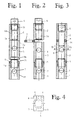
- the hinge includes three sleeve-shaped hinge parts 1, 2, and 3, of which the lower hinge part 1 and the upper hinge part 2 in a coaxial arrangement and at a defined distance one above the other at one of the two parts, preferably on the fixed door frame, are attached.
- the hinge parts 1, 2 can, for example, with their from Fig. 4 apparent Surfaces 4 welded to the door frame or - especially in a Wooden door and a wooden frame - to be screwed on.
- the third hinge part 3 with its surface 5 on the other part, preferably attached to the door.
- This hinged door attached to the door 3 is before the hinge assembly as an intermediate piece between the lower and the upper hinge part 1, 2 in an approximately coaxial Position brought with these two other hinge parts 1, 2, where he initially with its upper end face 3o at the lower end face 2u of the upper hinge part 2 is applied.
- the three sleeve-shaped hinge parts 1, 2, 3 have the same inner diameter or the same cross section (see Fig. 4).
- a bush 5 preferably pressed brass In a in the inner diameter extended part 1a of the lower hinge part 1 is the front side a bush 5 preferably pressed brass, the one the inner diameter of the lower hinge part 1 corresponding inner Diameter.
- the intermediate piece 3 is at its lower end provided with an enlarged inside diameter part 3b, with which it on a frontally upwardly projecting lug 5b of the sleeve 5 can be placed (see Fig. 2).
- the upper hinge part 2 is at its upper end with an inner Threaded part 2a provided, in which screwed from above a stud 6 is one, the one the inner diameter of the hinge part 2 and Also has the intermediate piece 3 corresponding pin part 6a. In the in 1 and 2 shown positions, the pin part 6a is located inside of the upper hinge part 2.
- Both the lower hinge part 1 and the intermediate piece are each a transverse bore 7 or 8 equipped.
- the inventive hinge could also have more than three hinge parts include (for example, the door with two and the door frame with three hinge parts per hinge), e.g. the lowest two hinge parts the hinge parts 1 shown in Fig. 1 to 3, 3 would correspond and through the other hinge parts from above Pen part protrude above the transverse bore of the lower intermediate piece would.
- the inventive hinge is manufacturing and assembly technology easy and inexpensive.
Landscapes
- Engineering & Computer Science (AREA)
- Mechanical Engineering (AREA)
- Hinges (AREA)
Applications Claiming Priority (2)
| Application Number | Priority Date | Filing Date | Title |
|---|---|---|---|
| CH4742004 | 2004-03-22 | ||
| CH474042004 | 2004-03-22 |
Publications (1)
| Publication Number | Publication Date |
|---|---|
| EP1580378A1 true EP1580378A1 (fr) | 2005-09-28 |
Family
ID=34842451
Family Applications (1)
| Application Number | Title | Priority Date | Filing Date |
|---|---|---|---|
| EP05405201A Withdrawn EP1580378A1 (fr) | 2004-03-22 | 2005-02-18 | Charnière |
Country Status (1)
| Country | Link |
|---|---|
| EP (1) | EP1580378A1 (fr) |
Citations (4)
| Publication number | Priority date | Publication date | Assignee | Title |
|---|---|---|---|---|
| US3857625A (en) * | 1973-07-16 | 1974-12-31 | Rixson Firemark | Electrical connector hinge |
| DE8803042U1 (de) * | 1988-03-07 | 1988-04-28 | Harders, Rolf, 6906 Leimen | Tür- oder Fensterscharnier mit Höhenregulierung (II) |
| US4839939A (en) * | 1988-03-24 | 1989-06-20 | Brien Ii James A O | Security hinge with improved structural integrity with the electrical wires located along the pivot axis of the knuckles |
| US20020112320A1 (en) * | 2001-02-22 | 2002-08-22 | Yazaki Corporation | Door hinge harness |
-
2005
- 2005-02-18 EP EP05405201A patent/EP1580378A1/fr not_active Withdrawn
Patent Citations (4)
| Publication number | Priority date | Publication date | Assignee | Title |
|---|---|---|---|---|
| US3857625A (en) * | 1973-07-16 | 1974-12-31 | Rixson Firemark | Electrical connector hinge |
| DE8803042U1 (de) * | 1988-03-07 | 1988-04-28 | Harders, Rolf, 6906 Leimen | Tür- oder Fensterscharnier mit Höhenregulierung (II) |
| US4839939A (en) * | 1988-03-24 | 1989-06-20 | Brien Ii James A O | Security hinge with improved structural integrity with the electrical wires located along the pivot axis of the knuckles |
| US20020112320A1 (en) * | 2001-02-22 | 2002-08-22 | Yazaki Corporation | Door hinge harness |
Similar Documents
| Publication | Publication Date | Title |
|---|---|---|
| DE3401245A1 (de) | Tuerscharnier fuer ein kraftfahrzeug | |
| DE102005020891A1 (de) | Brillenscharnier | |
| DE202008010722U1 (de) | Gelenkband und damit ausgestattete Duschkabine | |
| EP1881142B1 (fr) | Charnière | |
| EP3175068B1 (fr) | Système de ferrure | |
| EP3922798A1 (fr) | Porte dotée d'une charnière à absorption des chocs intégrée | |
| DE20309597U1 (de) | Türband für eine bei geschlossener Tür verdeckte Anordnung zwischen Türzarge und Türflügel | |
| EP1580378A1 (fr) | Charnière | |
| EP1160406A2 (fr) | Charnière avec surface d'appui encochée | |
| DE102005021206B4 (de) | Scharnier und Aufhängevorrichtung für eine Kraftfahrzeugtür | |
| EP1091069A2 (fr) | Charnière avec deux éléments relativement pivotants l'un par rapport à l'autre le long d'un axe commun de pivotement | |
| EP1308593A2 (fr) | Jonction de canal de câble entre un battant de porte et un cadre de porte | |
| DE102006001509B3 (de) | Scharnier für Türen oder Fenster sowie Verfahren zum Einsetzen eines für die Verstellung notwendigen Scharnierzapfens in einen Scharnierkopf bei einem Scharnier | |
| EP1201856B1 (fr) | Dispositif d'actionnement de volet | |
| DE7835006U1 (de) | Rückblickspiegel für Kraftfahrzeuge | |
| DE102011001626B4 (de) | Drehtür | |
| DE202009001411U1 (de) | Vorrichtung zum Verschliessen eines Durchgangs | |
| DE10012642B4 (de) | Gelenkbolzen für Scharniergelenke von Türen, Fenstern, Klappen o. dgl. | |
| DE9012710U1 (de) | Federscharnier für Brillen | |
| EP1757762B1 (fr) | Articulation à charnière, pour fenêtres, portes ou similaires | |
| DE3506724C2 (fr) | ||
| CH705664B1 (de) | Scharnier, insbesondere für eine Türe. | |
| DE202004020685U1 (de) | Türschließer | |
| DE102009006969A1 (de) | Vorrichtung zum Verschliessen eines Durchgangs | |
| WO2008077613A2 (fr) | Protection contre le coincement des doigts |
Legal Events
| Date | Code | Title | Description |
|---|---|---|---|
| PUAI | Public reference made under article 153(3) epc to a published international application that has entered the european phase |
Free format text: ORIGINAL CODE: 0009012 |
|
| AK | Designated contracting states |
Kind code of ref document: A1 Designated state(s): AT BE BG CH CY CZ DE DK EE ES FI FR GB GR HU IE IS IT LI LT LU MC NL PL PT RO SE SI SK TR |
|
| AX | Request for extension of the european patent |
Extension state: AL BA HR LV MK YU |
|
| AKX | Designation fees paid | ||
| REG | Reference to a national code |
Ref country code: DE Ref legal event code: 8566 |
|
| STAA | Information on the status of an ep patent application or granted ep patent |
Free format text: STATUS: THE APPLICATION IS DEEMED TO BE WITHDRAWN |
|
| 18D | Application deemed to be withdrawn |
Effective date: 20060329 |