EP1580360A2 - Actuator for motor vehicles - Google Patents
Actuator for motor vehicles Download PDFInfo
- Publication number
- EP1580360A2 EP1580360A2 EP05005422A EP05005422A EP1580360A2 EP 1580360 A2 EP1580360 A2 EP 1580360A2 EP 05005422 A EP05005422 A EP 05005422A EP 05005422 A EP05005422 A EP 05005422A EP 1580360 A2 EP1580360 A2 EP 1580360A2
- Authority
- EP
- European Patent Office
- Prior art keywords
- push rod
- stop
- actuator
- actuator according
- spring
- Prior art date
- Legal status (The legal status is an assumption and is not a legal conclusion. Google has not performed a legal analysis and makes no representation as to the accuracy of the status listed.)
- Granted
Links
Images
Classifications
-
- E—FIXED CONSTRUCTIONS
- E05—LOCKS; KEYS; WINDOW OR DOOR FITTINGS; SAFES
- E05B—LOCKS; ACCESSORIES THEREFOR; HANDCUFFS
- E05B81/00—Power-actuated vehicle locks
- E05B81/24—Power-actuated vehicle locks characterised by constructional features of the actuator or the power transmission
- E05B81/25—Actuators mounted separately from the lock and controlling the lock functions through mechanical connections
Definitions
- the invention relates to an actuator for motor vehicles, in particular for Actuation of a sliding door closing device, with a motor between at least two different positions longitudinally movable push rod, and with an actuator connected to the push rod.
- Actuators are widely known in the automotive sector. So deals the generic type DE 42 21 671 A1 with an actuating element, which for the unlocking of a locking device ensures.
- an actuator is provided, which of an electric motor via a pinion against the force a return spring from a first end position to a second end position movable and with switched off electric motor by means of the return spring of the second can be reset to the first end position.
- the resetting happens in the present example, for example, such that a boot lid is closed is, so that there referred to as a ram push rod in one of the two Final positions is transferred. Manual loading of the push rod or the plunger thus corresponds directly to their or its movement against the force of the return spring.
- EP 0 764 751 B1 also discloses a generic one Actuator.
- a thread-free wave area at the Push rod provided, which upon movement of the push rod a Torsion of an associated shaft of a spindle drive allows. This can to dispense with a slip clutch to damage the actuator by the torque of the associated electric motor when moving to avoid the push rod on the end stops.
- the invention is based on the technical problem of a generic Actuator for motor vehicles to develop so that the actuator can also be operated at a blockage of the push rod.
- an emergency operating device for the mentioned freewheeling of the actuator with blocked motor and consequentially fixed push rod and at the same time manual operation of the Stellianos ensures.
- the actuator is connected to the push rod, to follow the movements of the engine.
- the mentioned connection is designed so that a fixed Push rod nevertheless a certain travel of the control element (manual Admission). This freewheel does not come at a normal function of the engine or electric motor used.
- connection of the control element to the push rod via a recording in which the actuator engages with an arm or otherwise.
- this retains Recording their cross-sectional size, so that the actuator force and / or positively entrained. But blocks the engine or the Push rod, for example, as a result of an accident, so ensures a movable Stop for the actuator on the push rod to realize the freewheel. Because this stop can with manual actuation of the actuating element and blocked motor or fixed push rod.
- the movable stop does not dodge, because insofar as a stop spring on said stop prevents this avoidance.
- This spring is sized so that the connected to a normal operation Actuating forces they do not compress or at most slightly capital. However, if the engine and consequently the push rod is blocked, so the spring in question can be compressed manually, so as a result thereof the movable stop increases the cross-sectional area of the receptacle and so realized the freewheel.
- this recording trained spring-loaded stop along with a bow on the push rod a receiving eye, in which the actuator nieddus engages so as to the initiated by the motor longitudinal movements of the To follow push rod.
- the stop as in a guide of the push rod form longitudinally displaceable sliding element.
- the Push rod like the slider in question over one or more lateral Guide tongues have, in associated guide slots in the Engage push rod and so for a longitudinal guide of the stop or Sliding provide opposite the push rod, namely a guide in the longitudinal direction of the push rod.
- stop spring In order to keep the already mentioned stop spring for the stop, has this on its side facing away from the actuating element via a retaining pin, which carries the respective stop spring.
- the stop spring supports on the one hand on the movable stop and on the other hand on the Push rod and is preferably designed as a longitudinally extending coil spring.
- a particularly compact design is achieved when the push rod a having a spindle drive engaged thread has. Because in In such a case can be dispensed with a mostly mandatory spindle nut which in turn acts on the push rod. That is, the said Spindle nut and the push rod are within the scope of the invention and made in one piece for cost reasons.
- has the Spindle drive via a threaded spindle possibly with the interposition of a Gearbox driven by the already mentioned motor or electric motor becomes.
- the threaded spindle meshes with the thread in the Push rod, allowing rotations of the threaded spindle in linear motion the push rod to be implemented.
- the push rod is located outside of a housing in which the Spindle drive including motor and possibly gearbox is added. There One foot of the push rod ensures that the push rod in the relevant Housing is guided. In addition, the spindle drive still has one Return spring, which the push rod in one of the two already transferred positions.
- the described Actuator even more than the two specified positions or end positions take, if necessary.
- the described Actuator even more than the two specified positions or end positions take, if necessary.
- the described Actuator even more than the two specified positions or end positions take, if necessary.
- the described Actuator even more than the two specified positions or end positions take, if necessary.
- the described Actuator even more than the two specified positions or end positions take, if necessary.
- the described Actuator even more than the two specified positions or end positions take, if necessary.
- the described Actuator even more than the two specified positions or end positions take, if necessary.
- the described Actuator even more than the two specified positions or end positions take,
- the interpretation of the push rod and the spindle drive is a total made such that with manual actuation of the actuating element only the Stop spring and then the return spring is compressed. That is, the Self - locking of the spindle drive in conjunction with the spring constants of the Return spring builds up enough large opposing forces, so that when blocked Push rod always first the stop spring is compressed and as a result of described opposing forces the push rod retains its overall position. Of course, then the return spring leaves a change in the position of the Push rod to when the movable stop in its final position of Freewheel is located and unchanged high manual actuation forces on the Attacking actuator and not intercepted by other attacks become.
- an actuator for motor vehicles has an emergency operating device that allows it to be fixed
- push rod still provide for a manual movement of the control element to be able to.
- This achieves a mechanical redundancy that allows For example, a locking device to unlock and open, and Although also with failed or defective motor drive or spindle drive. All of this succeeds in a simple and functional design.
- the main advantages can be seen.
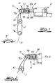
- an actuator for motor vehicles is shown.
- this actuator ensures that with the help of a control element 1 not one Expressed sliding door closure device unlocked and / or opened is, by means of a motor 2 and / or manually.
- the relevant motor vehicle door lock can be open motor and expose the sliding door if necessary.
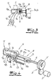
- This spindle drive 2, 3, 3 ', 4, 5 consists essentially of the engine 2, a connected thereto Gear 3, one of the gear 3 rotatably driven threaded spindle 4 and a spindle nut 5 together.
- the spindle nut 5 meshes with the threaded spindle 4 and can as a result of their rotations linear movements run in the longitudinal direction of a push rod 6. This indicates a double arrow in Fig. 4 at.
- the spindle nut 5 is an integral part of the push rod 6, although also, a separate interpretation of the inventive concept is included.
- 3, 3 ', 4, 5 is in total in a two-part housing 7a, 7b taken, which composed of two housing halves 7a, 7b is, which are latched together.
- the push rod is with her foot 8 in the respective housing 7 or 7a, 7b out.
- the foot 8 of the push rod 6 is composed of two Webs 8a, 8b together, each sealingly in associated slots in the housing 7 are taken longitudinally displaceable.
- the actuator 1 is connected to the push rod 6.
- This has the Push rod 6 via a foot 8 opposite head-side eyelet 9, the is composed of a ⁇ senbogen 9a and a stop 9b.
- the Stop 9b is thus part of a receptacle or eyelet 9 for the actuating element. 1 So that the actuator 1 can follow the movements of the push rod 6, grab it with one end in the eyelet 9 in question.
- a position of the longitudinally movable push rod 6 is shown, the so-called rest position or normal position, which automatically when switched off Engine 2 is taken.
- This is ensured by a spindle drive 2, 3, 3 ', 4, 5 associated return spring 3', which are embedded in a gear of the transmission 3 is, as the Fig. 4 indicated.
- the tensioned return spring provides 3 'for the fact that the control element 1, the rest position of FIG. 1 (again) occupies.
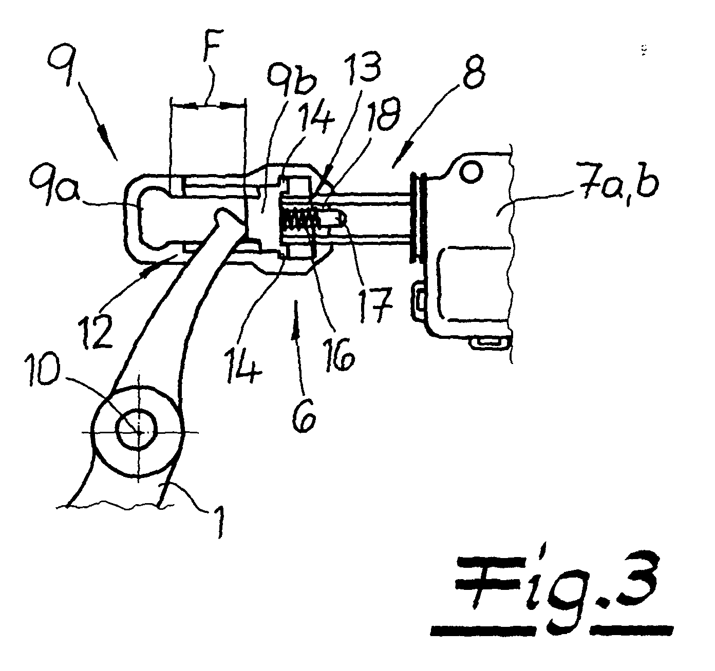
- the stop 9b differs, as far as through the Freewheel F is allowed. In fact, this freewheel F is measured by means of two stops 12, 13.
- the one stop 12 is the head side of Push rod 6 realized and corresponds to the fact that the movable stop 9b with its two lateral guide tongues 14, the head end reaches two associated guide slots 15 in the push rod 6.
- the leadership tongues 14 together with the guide slots 15 form a guide or longitudinal guide 14, 15 for the sliding element formed as 9b stop 9b.
- the other stop 13 is automatically reached when a stop 9b acting and formed in the embodiment as a coil spring 16 Stop spring 16 is completely compressed, as shown in FIG. 3 represents.
- Retaining pin 17 which extends in the longitudinal direction of the push rod 6 of the Actuator 1 facing away from the stop 9b extending starting.
- the Spiral spring 16 is supported on the one hand on the movable stop 9b and on the other hand on the push rod 6, and indeed there in a receptacle 18th
- the design is such that when manual actuation of the actuating element 1 with the help of the handle 11 'including connecting means 11 the Push rod 6 maintains its rest position corresponding to FIGS. 1 and 3.
- the means, the self-locking forces of the spindle drive 2, 3, 3 ', 4, 5 are in communication with the forces built up by the return spring 3 'so great that always first compresses the coil spring 16 as shown in Fig. 3 becomes. Only if unchanged, the handle 11 'including connecting means 11 acted upon and further than the pivotal movements shown in Fig.
Landscapes
- Lock And Its Accessories (AREA)
- Power-Operated Mechanisms For Wings (AREA)
Abstract
Gegenstand der vorliegenden Erfindung ist ein Stellantrieb für Kraftfahrzeuge,
insbesondere zur Betätigung einer Schiebetür-Schließeinrichtung. Der Stellantrieb
verfügt über eine motorisch zwischen wenigstens zwei Positionen längsbewegbare
Schubstange (6). Außerdem ist ein an die Schubstange (6) angeschlossenes
Stellelement (1) realisiert. Erfindungsgemäß vollführt das Stellelement
(1) bei blockiertem Motor (2) und manueller Betätigung einen Freilauf
(F) gegenüber der fixierten Schubstange (6).
Description
Die Erfindung betrifft einen Stellantrieb für Kraftfahrzeuge, insbesondere zur Betätigung einer Schiebetür-Schließeinrichtung, mit einer motorisch zwischen wenigstens zwei verschiedenen Positionen längsbewegbaren Schubstange, und mit einem an die Schubstange angeschlossenen Stellelement.The invention relates to an actuator for motor vehicles, in particular for Actuation of a sliding door closing device, with a motor between at least two different positions longitudinally movable push rod, and with an actuator connected to the push rod.
Stellantriebe sind auf dem Kraftfahrzeugsektor vielfältig bekannt. So befasst sich die gattungsbildende DE 42 21 671 A1 mit einem Stellelement, welches für die Entriegelung einer Schließeinrichtung sorgt. Dazu ist ein Stellglied vorgesehen, welches von einem Elektromotor über einen Zahntrieb gegen die Kraft einer Rückstellfeder von einer ersten Endposition in eine zweite Endposition bewegbar und bei abgeschaltetem Elektromotor mittels der Rückstellfeder von der zweiten in die erste Endposition rückstellbar ist. Das Rückstellen geschieht vorliegend beispielsweise dergestalt, dass ein Kofferraumdeckel geschlossen wird, so dass die dort als Stößel bezeichnete Schubstange in eine der beiden Endpositionen überführt wird. Die manuelle Beaufschlagung der Schubstange bzw. des Stößels korrespondiert also unmittelbar zu deren bzw. dessen Bewegung gegen die Kraft der Rückstellfeder.Actuators are widely known in the automotive sector. So deals the generic type DE 42 21 671 A1 with an actuating element, which for the unlocking of a locking device ensures. For this purpose, an actuator is provided, which of an electric motor via a pinion against the force a return spring from a first end position to a second end position movable and with switched off electric motor by means of the return spring of the second can be reset to the first end position. The resetting happens in the present example, for example, such that a boot lid is closed is, so that there referred to as a ram push rod in one of the two Final positions is transferred. Manual loading of the push rod or the plunger thus corresponds directly to their or its movement against the force of the return spring.
Daneben kennt man durch die EP 0 764 751 B1 ebenfalls einen gattungsgemäßen Stellantrieb. Hier ist ein gewindefreier Wellenbereich an der Schubstange vorgesehen, welcher bei Bewegung der Schubstange eine Torsion einer zugehörigen Welle eines Spindeltriebes ermöglicht. Dadurch kann auf eine Rutschkupplung verzichtet werden, um Beschädigungen des Stellantriebes durch das Drehmoment des zugehörigen Elektromotors beim Bewegen der Schubstange auf die Endanschläge hin zu vermeiden. In addition, EP 0 764 751 B1 also discloses a generic one Actuator. Here is a thread-free wave area at the Push rod provided, which upon movement of the push rod a Torsion of an associated shaft of a spindle drive allows. This can to dispense with a slip clutch to damage the actuator by the torque of the associated electric motor when moving to avoid the push rod on the end stops.
Die bekannten Stellantriebe haben sich bewährt, stoßen jedoch dann an ihre Grenzen, wenn eine mechanische Redundanz gefordert wird. Kommt beispielsweise ein Stellantrieb bei einer Kraftfahrzeugtür, insbesondere Schiebetür, zum Einsatz, um den zugehörigen Kraftfahrzeugtürverschluss zu entriegeln und/oder (elektrisch) zu öffnen, so ergibt sich die Forderung, dass bei einem Ausfall der beschriebenen Betätigungskette beispielsweise im Anschluss an einen Unfall dennoch die zugehörige Kraftfahrzeugtür problemlos geöffnet werden können muss. Das heißt, die manuelle Bewegung des Stellelementes muss auch bei Blockade des Motors und folglich der längsbewegbaren Schubstange gewährleistet werden, um den Kraftfahrzeugtürverschluss und im Anschluss hieran die Kraftfahrzeugtür öffnen zu können. Das ist mit den bisherigen Stellantrieben nicht möglich. Hier setzt die Erfindung ein.The known actuators have proven themselves, but then come to their Limits when mechanical redundancy is required. Comes for example an actuator in a motor vehicle door, in particular sliding door, used to unlock the associated vehicle door latch and / or (electrically) to open, so there is the requirement that at a Failure of the described actuator chain, for example, following an accident still the associated motor vehicle door easily opened must be able to. That is, the manual movement of the actuator must also be in case of blockage of the engine and consequently the longitudinally movable Push rod be guaranteed to the motor vehicle door lock and in the Connection to open the vehicle door. That's with the previous ones Actuators not possible. This is where the invention starts.
Der Erfindung liegt das technische Problem zugrunde, einen gattungsgemäßen Stellantrieb für Kraftfahrzeuge so weiter zu entwickeln, dass das Stellelement auch bei einer Blockade der Schubstange betätigt werden kann.The invention is based on the technical problem of a generic Actuator for motor vehicles to develop so that the actuator can also be operated at a blockage of the push rod.
Zur Lösung dieser technischen Problemstellung ist ein gattungsgemäßer Stellantrieb im Rahmen der Erfindung dadurch gekennzeichnet, dass das Stellelement bei blockiertem Motor und manueller Betätigung einen Freilauf gegenüber der fixierten Schubstange vollführt.To solve this technical problem is a generic Actuator in the invention characterized in that the adjusting element with blocked engine and manual operation, a freewheeling opposite the fixed push rod performs.
Erfindungsgemäß wird also eine Notfallbetätigungseinrichtung vorgeschlagen, die für den erwähnten Freilauf des Stellelementes bei blockiertem Motor und folgerichtig fixierter Schubstange und bei gleichzeitig manueller Betätigung des Stellelementes sorgt. Das Stellelement ist an die Schubstange angeschlossen, um den Bewegungen des Motors folgen zu können. Durch den Freilauf wird nun erreicht, dass der erwähnte Anschluss so ausgestaltet ist, dass eine fixierte Schubstange dennoch einen gewissen Stellweg des Stellelementes (bei manueller Beaufschlagung) zulässt. Dabei kommt dieser Freilauf nicht bei einer normalen Funktion des Motors bzw. Elektromotors zum Einsatz.According to the invention, therefore, an emergency operating device is proposed, for the mentioned freewheeling of the actuator with blocked motor and consequentially fixed push rod and at the same time manual operation of the Stellelementes ensures. The actuator is connected to the push rod, to follow the movements of the engine. Through the freewheel is now achieved that the mentioned connection is designed so that a fixed Push rod nevertheless a certain travel of the control element (manual Admission). This freewheel does not come at a normal function of the engine or electric motor used.
Im Detail erfolgt der Anschluss des Stellelementes an die Schubstange über eine Aufnahme, in welche das Stellelement mit einem Arm oder sonst wie eingreift. Bei normalem Betrieb, das heißt nicht blockiertem Motor, behält diese Aufnahme ihre Querschnittsgröße bei, so dass das Stellelement kraft- und/oder formschlüssig mitgenommen wird. Blockiert jedoch der Motor bzw. die Schubstange beispielsweise infolge eines Unfalles, so sorgt ein beweglicher Anschlag für das Stellelement an der Schubstange zur Realisierung des Freilaufes. Denn dieser Anschlag kann bei manueller Betätigung des Stellelementes und blockiertem Motor bzw. fixierter Schubstange ausweichen.In detail, the connection of the control element to the push rod via a recording in which the actuator engages with an arm or otherwise. In normal operation, that is unblocked engine, this retains Recording their cross-sectional size, so that the actuator force and / or positively entrained. But blocks the engine or the Push rod, for example, as a result of an accident, so ensures a movable Stop for the actuator on the push rod to realize the freewheel. Because this stop can with manual actuation of the actuating element and blocked motor or fixed push rod.
Solange also mit einem normalen Motorbetrieb verbundene Kräfte über die Schubstange und den Anschlag in das Stellelement zum Bewegen des Stellelementes eingeleitet werden, weicht der bewegliche Anschlag nicht aus, weil insofern eine Anschlagfeder am besagten Anschlag dieses Ausweichen verhindert. Diese Feder ist so bemessen, dass die mit einem Normalbetrieb verbundenen Betätigungskräfte sie nicht oder allenfalls geringfügig zu komprimieren vermögen. Ist jedoch der Motor und folgerichtig die Schubstange blockiert, so kann die betreffende Feder manuell komprimiert werden, so dass als Folge hiervon der bewegliche Anschlag die Querschnittsfläche der Aufnahme vergrößert und so den Freilauf realisiert. In der Regel formt der als Teil dieser Aufnahme ausgebildete federbeaufschlagte Anschlag zusammen mit einem Bogen an der Schubstange eine Aufnahmeöse, in welche das Stellelement einendseitig eingreift, um so den durch den Motor initiierten Längsbewegungen der Schubstange folgen zu können.So as long as connected with a normal engine operation forces on the Push rod and the stop in the actuator for moving the actuator be introduced, the movable stop does not dodge, because insofar as a stop spring on said stop prevents this avoidance. This spring is sized so that the connected to a normal operation Actuating forces they do not compress or at most slightly capital. However, if the engine and consequently the push rod is blocked, so the spring in question can be compressed manually, so as a result thereof the movable stop increases the cross-sectional area of the receptacle and so realized the freewheel. Usually forms as part of this recording trained spring-loaded stop along with a bow on the push rod a receiving eye, in which the actuator einendseitig engages so as to the initiated by the motor longitudinal movements of the To follow push rod.
Es hat sich bewährt, den Anschlag als in einer Führung der Schubstange längsverschiebbares Gleitelement auszubilden. Zur Führung in der Schubstange mag das betreffende Gleitelement über ein oder mehrere seitliche Führungszungen verfügen, die in zugehörige Führungsschlitze in der Schubstange eingreifen und so für eine Längsführung des Anschlages bzw. Gleitelementes gegenüber der Schubstange sorgen, nämlich für eine Führung in Längsrichtung der Schubstange.It has proven to be the stop as in a guide of the push rod form longitudinally displaceable sliding element. For guidance in the Push rod like the slider in question over one or more lateral Guide tongues have, in associated guide slots in the Engage push rod and so for a longitudinal guide of the stop or Sliding provide opposite the push rod, namely a guide in the longitudinal direction of the push rod.
Um die bereits angesprochene Anschlagfeder für den Anschlag zu halten, verfügt dieser an seiner dem Stellelement abgewandten Seite über einen Haltezapfen, welcher die betreffende Anschlagfeder trägt. Die Anschlagfeder stützt sich einerseits an dem beweglichen Anschlag und andererseits an der Schubstange ab und ist bevorzugt als längserstreckte Spiralfeder ausgebildet.In order to keep the already mentioned stop spring for the stop, has this on its side facing away from the actuating element via a retaining pin, which carries the respective stop spring. The stop spring supports on the one hand on the movable stop and on the other hand on the Push rod and is preferably designed as a longitudinally extending coil spring.
Ein besonders kompakter Aufbau wird erreicht, wenn die Schubstange einen mit einem Spindeltrieb im Eingriff befindlichen Gewindegang besitzt. Denn in einem solchen Fall kann auf eine zumeist obligatorische Spindelmutter verzichtet werden, die ihrerseits die Schubstange beaufschlagt. Das heißt, die besagte Spindelmutter und die Schubstange sind im Rahmen der Erfindung und aus Kostengründen einstückig ausgeführt. Wie allgemein bekannt, verfügt der Spindeltrieb über eine Gewindespindel, die ggf. unter Zwischenschaltung eines Getriebes von dem bereits angesprochenen Motor bzw. Elektromotor angetrieben wird. Die Gewindespindel kämmt mit dem Gewindegang in der Schubstange, so dass Drehungen der Gewindespindel in Linearbewegungen der Schubstange umgesetzt werden.A particularly compact design is achieved when the push rod a having a spindle drive engaged thread has. Because in In such a case can be dispensed with a mostly mandatory spindle nut which in turn acts on the push rod. That is, the said Spindle nut and the push rod are within the scope of the invention and made in one piece for cost reasons. As is well known, has the Spindle drive via a threaded spindle, possibly with the interposition of a Gearbox driven by the already mentioned motor or electric motor becomes. The threaded spindle meshes with the thread in the Push rod, allowing rotations of the threaded spindle in linear motion the push rod to be implemented.
Die Schubstange befindet sich außerhalb eines Gehäuses, in welchem der Spindeltrieb inklusive Motor sowie ggf. Getriebe aufgenommen wird. Dabei sorgt ein Fuß der Schubstange dafür, dass die Schubstange in dem betreffenden Gehäuse geführt wird. Zusätzlich verfügt der Spindeltrieb noch über eine Rückstellfeder, welche die Schubstange in eine der beiden eingangs bereits beschriebenen Positionen überführt. Selbstverständlich kann der beschriebene Stellantrieb auch noch mehr als die beiden angegebenen Positionen bzw. Endpositionen einnehmen, falls dies erforderlich sein sollte. - Ebenso umfasst die Erfindung natürlich auch Varianten ohne Spindeltrieb, bei denen der Motor bzw. Elektromotor als Linearmotor unmittelbar die Schubstange antreibt. Auch ein Piezomotor ist an dieser Stelle denkbar.The push rod is located outside of a housing in which the Spindle drive including motor and possibly gearbox is added. there One foot of the push rod ensures that the push rod in the relevant Housing is guided. In addition, the spindle drive still has one Return spring, which the push rod in one of the two already transferred positions. Of course, the described Actuator even more than the two specified positions or end positions take, if necessary. - Likewise includes the Invention, of course, variants without spindle drive, in which the engine or Electric motor as a linear motor directly drives the push rod. Also a Piezomotor is conceivable at this point.
Schließlich ist die Auslegung der Schubstange und des Spindeltriebes insgesamt so getroffen, dass bei manueller Betätigung des Stellelementes erst die Anschlagfeder und dann die Rückstellfeder komprimiert wird. Das heißt, die Selbsthemmung des Spindeltriebes in Verbindung mit der Federkonstanten der Rückstellfeder baut genügend große Gegenkräfte auf, so dass bei blockierter Schubstange immer zuerst die Anschlagfeder komprimiert wird und infolge der beschriebenen Gegenkräfte die Schubstange insgesamt ihre Position beibehält. Selbstverständlich lässt die Rückstellfeder dann einen Wechsel der Position der Schubstange zu, wenn sich der bewegliche Anschlag in seiner Endposition des Freilaufes befindet und unverändert hohe manuelle Betätigungskräfte an dem Stellelement angreifen und nicht durch anderweitige Anschläge abgefangen werden.Finally, the interpretation of the push rod and the spindle drive is a total made such that with manual actuation of the actuating element only the Stop spring and then the return spring is compressed. That is, the Self - locking of the spindle drive in conjunction with the spring constants of the Return spring builds up enough large opposing forces, so that when blocked Push rod always first the stop spring is compressed and as a result of described opposing forces the push rod retains its overall position. Of course, then the return spring leaves a change in the position of the Push rod to when the movable stop in its final position of Freewheel is located and unchanged high manual actuation forces on the Attacking actuator and not intercepted by other attacks become.
Im Ergebnis wird ein Stellantrieb für Kraftfahrzeuge zur Verfügung gestellt, der über eine Notfallbetätigungseinrichtung verfügt, die es erlaubt, bei fixierter Schubstange dennoch für eine manuelle Bewegung des Stellelementes sorgen zu können. Dadurch wird eine mechanische Redundanz erreicht, die es ermöglicht, beispielsweise eine Schließeinrichtung zu entriegeln und zu öffnen, und zwar auch bei ausgefallenem oder defektem motorischen Antrieb bzw. Spindeltrieb. Das alles gelingt bei einfachem und funktionsgerechtem Aufbau. Hierin sind die wesentlichen Vorteile zu sehen.As a result, an actuator for motor vehicles is provided, the has an emergency operating device that allows it to be fixed However, push rod still provide for a manual movement of the control element to be able to. This achieves a mechanical redundancy that allows For example, a locking device to unlock and open, and Although also with failed or defective motor drive or spindle drive. All of this succeeds in a simple and functional design. Here in The main advantages can be seen.
Im Folgenden wird die Erfindung anhand einer lediglich ein Ausführungsbeispiel darstellenden Zeichnung näher erläutert; es zeigen:
- Fig. 1
- den erfindungsgemäßen Stellantrieb schematisch,
- Fig. 2
- den Gegenstand nach Fig. 1 vergrößert bei einer elektrischen Betätigung,
- Fig. 3
- den Gegenstand nach Fig. 1 bei manueller Betätigung und
- Fig. 4
- eine Explosionsdarstellung der Schubstange mit Einzelheiten.
- Fig. 1
- the actuator according to the invention schematically,
- Fig. 2
- the article of FIG. 1 increases in an electrical operation,
- Fig. 3
- the article of FIG. 1 with manual operation and
- Fig. 4
- an exploded view of the push rod with details.
In den Figuren ist ein Stellantrieb für Kraftfahrzeuge dargestellt. Vorliegend
sorgt dieser Stellantrieb dafür, dass mit Hilfe eines Stellelementes 1 eine nicht
ausdrücklich dargestellte Schiebetür-Schließeinrichtung entriegelt und/oder geöffnet
wird, und zwar mit Hilfe eines Motors 2 und/oder manuell. Zumeist erfolgt
die Entriegelung im Zuge eines Dialoges zwischen dem Kraftfahrzeug und
einem zutrittswilligen Bediener im Sinne einer "Keyless-Entry"-Zugangskontrolle.
Im Anschluss daran lässt sich der betreffende Kraftfahrzeugtürverschluss
motorisch öffnen und die Schiebetür ggf. ausstellen.In the figures, an actuator for motor vehicles is shown. present
this actuator ensures that with the help of a control element 1 not one
Expressed sliding door closure device unlocked and / or opened
is, by means of a
Dafür sorgt insgesamt ein Spindeltrieb 2, 3, 3', 4, 5. Dieser Spindeltrieb 2, 3, 3',
4, 5 setzt sich im Wesentlichen aus dem Motor 2, einem daran angeschlossenen
Getriebe 3, einer von dem Getriebe 3 rotativ angetriebenen Gewindespindel
4 und einer Spindelmutter 5 zusammen. Die Spindelmutter 5 kämmt mit
der Gewindespindel 4 und kann als Folge deren Rotationen Linearbewegungen
in Längsrichtung einer Schubstange 6 ausführen. Das deutet ein Doppelpfeil in
Fig. 4 an.This is ensured in total by a
Die Spindelmutter 5 ist integraler Bestandteil der Schubstange 6, wenngleich
auch eine getrennte Auslegung vom Erfindungsgedanken umfasst wird. Der
Spindeltrieb 2, 3, 3', 4, 5 wird insgesamt in einem zweiteiligen Gehäuse 7a, 7b
aufgenommen, welches aus zwei Gehäusehalbschalen 7a, 7b zusammengesetzt
ist, die rastend miteinander verbunden werden. Die Schubstange wird mit
ihrem Fuß 8 in dem betreffenden Gehäuse 7 bzw. 7a, 7b geführt. Im Rahmen
des Ausführungsbeispiels setzt sich der Fuß 8 der Schubstange 6 aus zwei
Stegen 8a, 8b zusammen, die jeweils dichtend in zugehörigen Schlitzen im Gehäuse
7 längsverschiebbar aufgenommen werden.The spindle nut 5 is an integral part of the
Das Stellelement 1 ist an die Schubstange 6 angeschlossen. Dazu verfügt die
Schubstange 6 über eine dem Fuß 8 gegenüberliegende kopfseitige Öse 9, die
sich aus einem Ösenbogen 9a sowie einem Anschlag 9b zusammensetzt. Der
Anschlag 9b ist also Teil einer Aufnahme bzw. der Öse 9 für das Stellelement 1.
Damit das Stellelement 1 den Bewegungen der Schubstange 6 folgen kann,
greift es mit einem Ende in die betreffende Öse 9 ein.The actuator 1 is connected to the
In der Fig. 1 ist eine Position der längsbewegbaren Schubstange 6 dargestellt,
die sogenannte Ruhestellung oder Normalstellung, die automatisch bei abgeschaltetem
Motor 2 eingenommen wird. Hierfür sorgt eine zum Spindeltrieb 2, 3,
3', 4, 5 gehörige Rückstellfeder 3', die in ein Zahnrad des Getriebes 3 eingelassen
ist, wie die Fig. 4 angedeutet. Bewegt der Motor bzw. Elektromotor 2 die
Schubstange 6 aus der Ruhestellung nach Fig. 1 in die Arbeitsstellung bzw.
Position entsprechend der Fig. 2, so wird die betreffende Rückstellfeder 3' gespannt.
Bei abgeschaltetem Elektromotor 2 sorgt die gespannte Rückstellfeder
3' dafür, dass das Stellelement 1 die Ruhestellung nach Fig. 1 (wieder) einnimmt.
Bei der Rückstellfeder 3' handelt es sich um eine Spiralfeder, wie sie
beispielsweise in dem Gebrauchsmuster DE 86 21 592 U1 bei einem Stelltrieb
beschrieben wird. Der vorliegende Spindeltrieb 2, 3, 3', 4, 5 ist vergleichbar aufgebaut,
wie in dem vorgenannten Gebrauchsmuster beschrieben, so dass
hierauf ausdrücklich verwiesen sei. 1, a position of the longitudinally
Kommt es zu einer Blockade des Motors bzw. Elektromotors 2 respektive der
Schubstange 6 beispielsweise infolge eines Autounfalls, so muss dennoch
gewährleistet werden können, dass das Stellelement 1 die zu einer Entriegelung
respektive Öffnung notwenige und in Fig. 1 angedeutete Schwenkbewegung
im Uhrzeigersinn um ihre Achse 10 vollführen kann. Zu diesem Zweck ist
bei manueller Betätigung des Stellelementes 1 ein Freilauf F des Stellelementes
1 gegenüber der fixierten Schubstange 6 realisiert, wie die Fig. 3 deutlich
macht. Um die manuelle Betätigung des Stellelementes 1 zu bewirken, ist das
Stellelement 1 an der der Öse 9 gegenüberliegenden Seite in Bezug auf die
Achse 10 mit einer Verbindungseinrichtung 11 ausgerüstet, die sich über eine
lediglich in Fig. 1 angedeutete Handhabe 11' betätigen lässt und für die beschriebene
Uhrzeigersinndrehung des Stellelementes 1 sorgt.If there is a blockade of the motor or
Im Zuge der manuellen Betätigung des Stellelementes 1 bei blockierter
Schubstange 6 weicht der Anschlag 9b aus, und zwar so weit, wie durch den
Freilauf F erlaubt wird. Tatsächlich bemisst sich dieser Freilauf F anhand von
zwei Anschlägen 12, 13. Der eine Anschlag 12 ist dabei kopfseitig der
Schubstange 6 realisiert und korrespondiert dazu, dass der bewegliche Anschlag
9b mit seinen zwei seitlichen Führungszungen 14 das kopfseitige Ende
zweier zugehöriger Führungsschlitze 15 in der Schubstange 6 erreicht. Die Führungszungen
14 bilden zusammen mit den Führungsschlitzen 15 eine Führung
bzw. Längsführung 14, 15 für den als Gleitelement 9b ausgebildeten Anschlag
9b.In the course of manual actuation of the control element 1 when blocked
Der andere Anschlag 13 wird automatisch dann erreicht, wenn eine den Anschlag
9b beaufschlagende und im Ausführungsbeispiel als Spiralfeder 16 ausgebildete
Anschlagfeder 16 vollständig komprimiert ist, wie die Fig. 3 darstellt.
Zur Führung und Aufnahme dieser längserstreckten Spiralfeder 16 dient ein
Haltezapfen 17, welcher sich in Längsrichtung der Schubstange 6 von der dem
Stellelement 1 abgewandten Seite des Anschlages 9b ausgehend erstreckt. Die
Spiralfeder 16 stützt sich einerseits an dem beweglichen Anschlag 9b und
andererseits an der Schubstange 6 ab, und zwar dort in einer Aufnahme 18.The
Die Auslegung ist so getroffen, dass bei manueller Betätigung des Stellelementes
1 mit Hilfe der Handhabe 11' inklusive Verbindungsmittel 11 die
Schubstange 6 ihre Ruhestellung entsprechend den Fig. 1 und 3 beibehält. Das
heißt, die Selbsthemmungskräfte des Spindeltriebes 2, 3, 3', 4, 5 sind in Verbindung
mit den von der Rückstellfeder 3' aufgebauten Kräfte so groß, dass
immer zuerst die Spiralfeder 16 entsprechend der Darstellung in Fig. 3 komprimiert
wird. Nur wenn unverändert die Handhabe 11' inklusive Verbindungsmittel
11 beaufschlagt und weitergehende als die in Fig. 3 dargestellten Schwenkbewegungen
des Stellelementes 1 im Uhrzeigersinn zugelassen werden, sorgt
das dann am Anschlag 13 anliegende Gleitelement 9b dafür, dass ergänzende
Schwenkbewegungen die Rückstellfeder 3', komprimieren und der Spindeltrieb
2, 3, 3', 4, 5 zurückgedreht wird. Fallen diese Zusatzkräfte weg, sorgt die sich
entspannende Rückstellfeder 3' dafür, dass die Schubstange 6 (wieder) ihre
Normalstellung nach den Fig. 1 und 3 einnimmt.The design is such that when manual actuation of the actuating element
1 with the help of the handle 11 'including connecting
Claims (10)
Applications Claiming Priority (2)
| Application Number | Priority Date | Filing Date | Title |
|---|---|---|---|
| DE102004012573 | 2004-03-12 | ||
| DE102004012573A DE102004012573A1 (en) | 2004-03-12 | 2004-03-12 | Actuator for motor vehicles |
Publications (3)
| Publication Number | Publication Date |
|---|---|
| EP1580360A2 true EP1580360A2 (en) | 2005-09-28 |
| EP1580360A3 EP1580360A3 (en) | 2009-10-21 |
| EP1580360B1 EP1580360B1 (en) | 2011-05-11 |
Family
ID=34853985
Family Applications (1)
| Application Number | Title | Priority Date | Filing Date |
|---|---|---|---|
| EP05005422A Expired - Lifetime EP1580360B1 (en) | 2004-03-12 | 2005-03-10 | Actuator for motor vehicles |
Country Status (3)
| Country | Link |
|---|---|
| EP (1) | EP1580360B1 (en) |
| AT (1) | ATE509173T1 (en) |
| DE (1) | DE102004012573A1 (en) |
Families Citing this family (1)
| Publication number | Priority date | Publication date | Assignee | Title |
|---|---|---|---|---|
| DE202009010787U1 (en) * | 2009-08-10 | 2010-12-23 | Kiekert Ag | Actuator for applying motor vehicle control elements |
Family Cites Families (8)
| Publication number | Priority date | Publication date | Assignee | Title |
|---|---|---|---|---|
| DE4221671C2 (en) * | 1992-07-02 | 1998-07-02 | Mannesmann Vdo Ag | Actuator for unlocking a locking device |
| DE19501493B4 (en) * | 1995-01-19 | 2006-06-22 | Kiekert Ag | Motor vehicle door lock |
| DE19535437C2 (en) * | 1995-09-23 | 2001-10-18 | Hella Kg Hueck & Co | Electromotive actuator for motor vehicles |
| DE19706952A1 (en) * | 1997-02-21 | 1998-08-27 | Mannesmann Vdo Ag | Dirt-free opening handle for vehicle tailgates |
| DE10026528A1 (en) * | 2000-05-27 | 2001-12-06 | Bosch Gmbh Robert | Actuator for a motor vehicle door lock |
| DE10142134A1 (en) * | 2001-08-30 | 2003-03-20 | Kiekert Ag | Actuator for vehicle fuel flap and door locks, has spindle which is advanced and retracted producing an opening motion in each direction |
| DE10240552A1 (en) * | 2002-08-29 | 2004-03-11 | Brose Schließsysteme GmbH & Co.KG | Vehicle door lock has drive motor, drive shaft, reducing gear with gear stage, regulating elements, restoring element, worm and worm wheel |
| DE10251386A1 (en) * | 2002-11-01 | 2004-05-13 | Siemens Ag | Lever unit for motor vehicle door lock operated by both external and internal handles through common lever drive |
-
2004
- 2004-03-12 DE DE102004012573A patent/DE102004012573A1/en not_active Withdrawn
-
2005
- 2005-03-10 EP EP05005422A patent/EP1580360B1/en not_active Expired - Lifetime
- 2005-03-10 AT AT05005422T patent/ATE509173T1/en active
Also Published As
| Publication number | Publication date |
|---|---|
| EP1580360A3 (en) | 2009-10-21 |
| DE102004012573A1 (en) | 2005-10-06 |
| EP1580360B1 (en) | 2011-05-11 |
| ATE509173T1 (en) | 2011-05-15 |
Similar Documents
| Publication | Publication Date | Title |
|---|---|---|
| EP2342405B1 (en) | Motor vehicle lock | |
| EP2291571B1 (en) | Closing device comprising a detent spring | |
| EP1489252B1 (en) | Motor vehicle door lock | |
| DE102017108265A1 (en) | Lock for a motor vehicle | |
| DE102018123949A1 (en) | actuator | |
| EP2420642B1 (en) | Motor vehicle lock | |
| EP2094541A1 (en) | Electromechanical driving device for use in a tailgate of a motor vehicle | |
| WO2018113820A1 (en) | Motor vehicle door lock | |
| WO2016146109A1 (en) | Motor vehicle door | |
| DE102018101142A1 (en) | MOTOR VEHICLE LOCK | |
| EP3784855B1 (en) | Motor vehicle lock | |
| DE10242830A1 (en) | Motor vehicle lock has closing part operated by two or more electric motors | |
| EP2146032A1 (en) | Device for opening and/or shutting and locking a closed state of a shutting device for shutting a spatial opening and shutting device with such a device | |
| DE102009007686A1 (en) | Manual fixing device for use in drive crank for blocking e.g. lifting, of crank window in door of police vehicle, has adjusting part and gear functionally attached to each other such that gear causes contact of crank with lifting mechanism | |
| DE202014103819U1 (en) | Motor vehicle lock | |
| EP4158138B1 (en) | Drive unit for motor vehicle applications | |
| DE4407912C2 (en) | Electromechanical lock | |
| DE19946484B4 (en) | Drive device for a closure device of a vehicle tank filler neck | |
| DE102012107145A1 (en) | Tailgate lock for motor vehicle, has a delay unit which is coupled to a rotary latch, according to movement speed of latch, for the release of closing element, and a pawl set in release position when the latch is out of engagement | |
| DE10042191A1 (en) | Motor vehicle door lock with controlled actuator element has coupling with associated control mechanism that engages coupling if inner or outer door handle is operated | |
| DE19526660B4 (en) | Electromechanical lock | |
| EP1580360B1 (en) | Actuator for motor vehicles | |
| DE19628149B4 (en) | Device on a motor vehicle with tailgate | |
| WO2001066889A1 (en) | Lock for a vehicle door | |
| EP1498562B1 (en) | Locking device |
Legal Events
| Date | Code | Title | Description |
|---|---|---|---|
| PUAI | Public reference made under article 153(3) epc to a published international application that has entered the european phase |
Free format text: ORIGINAL CODE: 0009012 |
|
| AK | Designated contracting states |
Kind code of ref document: A2 Designated state(s): AT BE BG CH CY CZ DE DK EE ES FI FR GB GR HU IE IS IT LI LT LU MC NL PL PT RO SE SI SK TR |
|
| AX | Request for extension of the european patent |
Extension state: AL BA HR LV MK YU |
|
| PUAL | Search report despatched |
Free format text: ORIGINAL CODE: 0009013 |
|
| AK | Designated contracting states |
Kind code of ref document: A3 Designated state(s): AT BE BG CH CY CZ DE DK EE ES FI FR GB GR HU IE IS IT LI LT LU MC NL PL PT RO SE SI SK TR |
|
| AX | Request for extension of the european patent |
Extension state: AL BA HR LV MK YU |
|
| RIC1 | Information provided on ipc code assigned before grant |
Ipc: E05B 65/12 20060101AFI20090911BHEP |
|
| AKX | Designation fees paid |
Designated state(s): AT BE BG CH CY LI |
|
| 17P | Request for examination filed |
Effective date: 20100415 |
|
| RBV | Designated contracting states (corrected) |
Designated state(s): AT BE BG CH CY CZ DE DK EE ES FI FR GB GR HU IE IS IT LI LT LU MC NL PL PT RO SE SI SK TR |
|
| RAP1 | Party data changed (applicant data changed or rights of an application transferred) |
Owner name: KIEKERT AKTIENGESELLSCHAFT Owner name: PEUGEOT CITROEN AUTOMOBILES SA |
|
| REG | Reference to a national code |
Ref country code: DE Ref legal event code: 8566 |
|
| GRAP | Despatch of communication of intention to grant a patent |
Free format text: ORIGINAL CODE: EPIDOSNIGR1 |
|
| GRAS | Grant fee paid |
Free format text: ORIGINAL CODE: EPIDOSNIGR3 |
|
| GRAA | (expected) grant |
Free format text: ORIGINAL CODE: 0009210 |
|
| AK | Designated contracting states |
Kind code of ref document: B1 Designated state(s): AT BE BG CH CY CZ DE DK EE ES FI FR GB GR HU IE IS IT LI LT LU MC NL PL PT RO SE SI SK TR |
|
| REG | Reference to a national code |
Ref country code: GB Ref legal event code: FG4D Free format text: NOT ENGLISH |
|
| REG | Reference to a national code |
Ref country code: CH Ref legal event code: EP |
|
| REG | Reference to a national code |
Ref country code: IE Ref legal event code: FG4D |
|
| REG | Reference to a national code |
Ref country code: DE Ref legal event code: R096 Ref document number: 502005011353 Country of ref document: DE Effective date: 20110622 |
|
| REG | Reference to a national code |
Ref country code: NL Ref legal event code: VDEP Effective date: 20110511 |
|
| PG25 | Lapsed in a contracting state [announced via postgrant information from national office to epo] |
Ref country code: SE Free format text: LAPSE BECAUSE OF FAILURE TO SUBMIT A TRANSLATION OF THE DESCRIPTION OR TO PAY THE FEE WITHIN THE PRESCRIBED TIME-LIMIT Effective date: 20110511 Ref country code: LT Free format text: LAPSE BECAUSE OF FAILURE TO SUBMIT A TRANSLATION OF THE DESCRIPTION OR TO PAY THE FEE WITHIN THE PRESCRIBED TIME-LIMIT Effective date: 20110511 Ref country code: PT Free format text: LAPSE BECAUSE OF FAILURE TO SUBMIT A TRANSLATION OF THE DESCRIPTION OR TO PAY THE FEE WITHIN THE PRESCRIBED TIME-LIMIT Effective date: 20110912 |
|
| PG25 | Lapsed in a contracting state [announced via postgrant information from national office to epo] |
Ref country code: CY Free format text: LAPSE BECAUSE OF FAILURE TO SUBMIT A TRANSLATION OF THE DESCRIPTION OR TO PAY THE FEE WITHIN THE PRESCRIBED TIME-LIMIT Effective date: 20110511 Ref country code: SI Free format text: LAPSE BECAUSE OF FAILURE TO SUBMIT A TRANSLATION OF THE DESCRIPTION OR TO PAY THE FEE WITHIN THE PRESCRIBED TIME-LIMIT Effective date: 20110511 Ref country code: IS Free format text: LAPSE BECAUSE OF FAILURE TO SUBMIT A TRANSLATION OF THE DESCRIPTION OR TO PAY THE FEE WITHIN THE PRESCRIBED TIME-LIMIT Effective date: 20110911 Ref country code: GR Free format text: LAPSE BECAUSE OF FAILURE TO SUBMIT A TRANSLATION OF THE DESCRIPTION OR TO PAY THE FEE WITHIN THE PRESCRIBED TIME-LIMIT Effective date: 20110812 Ref country code: FI Free format text: LAPSE BECAUSE OF FAILURE TO SUBMIT A TRANSLATION OF THE DESCRIPTION OR TO PAY THE FEE WITHIN THE PRESCRIBED TIME-LIMIT Effective date: 20110511 Ref country code: ES Free format text: LAPSE BECAUSE OF FAILURE TO SUBMIT A TRANSLATION OF THE DESCRIPTION OR TO PAY THE FEE WITHIN THE PRESCRIBED TIME-LIMIT Effective date: 20110822 |
|
| REG | Reference to a national code |
Ref country code: IE Ref legal event code: FD4D |
|
| PG25 | Lapsed in a contracting state [announced via postgrant information from national office to epo] |
Ref country code: NL Free format text: LAPSE BECAUSE OF FAILURE TO SUBMIT A TRANSLATION OF THE DESCRIPTION OR TO PAY THE FEE WITHIN THE PRESCRIBED TIME-LIMIT Effective date: 20110511 |
|
| PG25 | Lapsed in a contracting state [announced via postgrant information from national office to epo] |
Ref country code: IE Free format text: LAPSE BECAUSE OF FAILURE TO SUBMIT A TRANSLATION OF THE DESCRIPTION OR TO PAY THE FEE WITHIN THE PRESCRIBED TIME-LIMIT Effective date: 20110511 Ref country code: EE Free format text: LAPSE BECAUSE OF FAILURE TO SUBMIT A TRANSLATION OF THE DESCRIPTION OR TO PAY THE FEE WITHIN THE PRESCRIBED TIME-LIMIT Effective date: 20110511 Ref country code: CZ Free format text: LAPSE BECAUSE OF FAILURE TO SUBMIT A TRANSLATION OF THE DESCRIPTION OR TO PAY THE FEE WITHIN THE PRESCRIBED TIME-LIMIT Effective date: 20110511 |
|
| PG25 | Lapsed in a contracting state [announced via postgrant information from national office to epo] |
Ref country code: PL Free format text: LAPSE BECAUSE OF FAILURE TO SUBMIT A TRANSLATION OF THE DESCRIPTION OR TO PAY THE FEE WITHIN THE PRESCRIBED TIME-LIMIT Effective date: 20110511 Ref country code: SK Free format text: LAPSE BECAUSE OF FAILURE TO SUBMIT A TRANSLATION OF THE DESCRIPTION OR TO PAY THE FEE WITHIN THE PRESCRIBED TIME-LIMIT Effective date: 20110511 Ref country code: RO Free format text: LAPSE BECAUSE OF FAILURE TO SUBMIT A TRANSLATION OF THE DESCRIPTION OR TO PAY THE FEE WITHIN THE PRESCRIBED TIME-LIMIT Effective date: 20110511 Ref country code: DK Free format text: LAPSE BECAUSE OF FAILURE TO SUBMIT A TRANSLATION OF THE DESCRIPTION OR TO PAY THE FEE WITHIN THE PRESCRIBED TIME-LIMIT Effective date: 20110511 |
|
| PLBE | No opposition filed within time limit |
Free format text: ORIGINAL CODE: 0009261 |
|
| STAA | Information on the status of an ep patent application or granted ep patent |
Free format text: STATUS: NO OPPOSITION FILED WITHIN TIME LIMIT |
|
| 26N | No opposition filed |
Effective date: 20120214 |
|
| PG25 | Lapsed in a contracting state [announced via postgrant information from national office to epo] |
Ref country code: IT Free format text: LAPSE BECAUSE OF FAILURE TO SUBMIT A TRANSLATION OF THE DESCRIPTION OR TO PAY THE FEE WITHIN THE PRESCRIBED TIME-LIMIT Effective date: 20110511 |
|
| REG | Reference to a national code |
Ref country code: DE Ref legal event code: R097 Ref document number: 502005011353 Country of ref document: DE Effective date: 20120214 |
|
| BERE | Be: lapsed |
Owner name: KIEKERT A.G. Effective date: 20120331 Owner name: PEUGEOT CITROEN AUTOMOBILES SA Effective date: 20120331 |
|
| PG25 | Lapsed in a contracting state [announced via postgrant information from national office to epo] |
Ref country code: MC Free format text: LAPSE BECAUSE OF NON-PAYMENT OF DUE FEES Effective date: 20120331 |
|
| REG | Reference to a national code |
Ref country code: CH Ref legal event code: PL |
|
| GBPC | Gb: european patent ceased through non-payment of renewal fee |
Effective date: 20120310 |
|
| PG25 | Lapsed in a contracting state [announced via postgrant information from national office to epo] |
Ref country code: GB Free format text: LAPSE BECAUSE OF NON-PAYMENT OF DUE FEES Effective date: 20120310 Ref country code: BE Free format text: LAPSE BECAUSE OF NON-PAYMENT OF DUE FEES Effective date: 20120331 Ref country code: CH Free format text: LAPSE BECAUSE OF NON-PAYMENT OF DUE FEES Effective date: 20120331 Ref country code: LI Free format text: LAPSE BECAUSE OF NON-PAYMENT OF DUE FEES Effective date: 20120331 |
|
| REG | Reference to a national code |
Ref country code: AT Ref legal event code: MM01 Ref document number: 509173 Country of ref document: AT Kind code of ref document: T Effective date: 20120310 |
|
| PG25 | Lapsed in a contracting state [announced via postgrant information from national office to epo] |
Ref country code: BG Free format text: LAPSE BECAUSE OF FAILURE TO SUBMIT A TRANSLATION OF THE DESCRIPTION OR TO PAY THE FEE WITHIN THE PRESCRIBED TIME-LIMIT Effective date: 20110811 |
|
| PG25 | Lapsed in a contracting state [announced via postgrant information from national office to epo] |
Ref country code: AT Free format text: LAPSE BECAUSE OF NON-PAYMENT OF DUE FEES Effective date: 20120310 |
|
| PG25 | Lapsed in a contracting state [announced via postgrant information from national office to epo] |
Ref country code: TR Free format text: LAPSE BECAUSE OF FAILURE TO SUBMIT A TRANSLATION OF THE DESCRIPTION OR TO PAY THE FEE WITHIN THE PRESCRIBED TIME-LIMIT Effective date: 20110511 |
|
| PG25 | Lapsed in a contracting state [announced via postgrant information from national office to epo] |
Ref country code: LU Free format text: LAPSE BECAUSE OF NON-PAYMENT OF DUE FEES Effective date: 20120310 |
|
| PG25 | Lapsed in a contracting state [announced via postgrant information from national office to epo] |
Ref country code: HU Free format text: LAPSE BECAUSE OF FAILURE TO SUBMIT A TRANSLATION OF THE DESCRIPTION OR TO PAY THE FEE WITHIN THE PRESCRIBED TIME-LIMIT Effective date: 20050310 |
|
| REG | Reference to a national code |
Ref country code: FR Ref legal event code: PLFP Year of fee payment: 12 |
|
| REG | Reference to a national code |
Ref country code: FR Ref legal event code: PLFP Year of fee payment: 13 |
|
| REG | Reference to a national code |
Ref country code: FR Ref legal event code: PLFP Year of fee payment: 14 |
|
| PGFP | Annual fee paid to national office [announced via postgrant information from national office to epo] |
Ref country code: DE Payment date: 20240321 Year of fee payment: 20 |
|
| P01 | Opt-out of the competence of the unified patent court (upc) registered |
Effective date: 20240404 |
|
| PGFP | Annual fee paid to national office [announced via postgrant information from national office to epo] |
Ref country code: FR Payment date: 20240320 Year of fee payment: 20 |
|
| REG | Reference to a national code |
Ref country code: DE Ref legal event code: R071 Ref document number: 502005011353 Country of ref document: DE |