EP1580317A1 - Seilantriebsvorrichtung mit Hohlwellenmotor - Google Patents
Seilantriebsvorrichtung mit Hohlwellenmotor Download PDFInfo
- Publication number
- EP1580317A1 EP1580317A1 EP05101489A EP05101489A EP1580317A1 EP 1580317 A1 EP1580317 A1 EP 1580317A1 EP 05101489 A EP05101489 A EP 05101489A EP 05101489 A EP05101489 A EP 05101489A EP 1580317 A1 EP1580317 A1 EP 1580317A1
- Authority
- EP
- European Patent Office
- Prior art keywords
- hollow shaft
- pulley
- motor
- drive device
- shaft motor
- Prior art date
- Legal status (The legal status is an assumption and is not a legal conclusion. Google has not performed a legal analysis and makes no representation as to the accuracy of the status listed.)
- Granted
Links
- 239000000463 material Substances 0.000 claims description 19
- 238000001816 cooling Methods 0.000 claims description 16
- 239000011111 cardboard Substances 0.000 claims description 8
- 239000011087 paperboard Substances 0.000 claims description 7
- 230000002093 peripheral effect Effects 0.000 claims description 3
- 230000001360 synchronised effect Effects 0.000 claims description 2
- 238000000034 method Methods 0.000 abstract description 3
- 230000032258 transport Effects 0.000 abstract 1
- 230000005540 biological transmission Effects 0.000 description 12
- 238000004519 manufacturing process Methods 0.000 description 11
- 238000012545 processing Methods 0.000 description 11
- 239000000123 paper Substances 0.000 description 6
- 238000013461 design Methods 0.000 description 5
- 239000000110 cooling liquid Substances 0.000 description 4
- 238000012423 maintenance Methods 0.000 description 4
- 238000007689 inspection Methods 0.000 description 3
- 238000009434 installation Methods 0.000 description 3
- 239000007788 liquid Substances 0.000 description 3
- 239000011248 coating agent Substances 0.000 description 2
- 238000000576 coating method Methods 0.000 description 2
- 238000010276 construction Methods 0.000 description 2
- 238000001035 drying Methods 0.000 description 2
- 238000005516 engineering process Methods 0.000 description 2
- 239000002826 coolant Substances 0.000 description 1
- 230000008878 coupling Effects 0.000 description 1
- 238000010168 coupling process Methods 0.000 description 1
- 238000005859 coupling reaction Methods 0.000 description 1
- 238000011161 development Methods 0.000 description 1
- 230000000694 effects Effects 0.000 description 1
- 230000008030 elimination Effects 0.000 description 1
- 238000003379 elimination reaction Methods 0.000 description 1
- 230000017525 heat dissipation Effects 0.000 description 1
- 230000001590 oxidative effect Effects 0.000 description 1
- 239000011295 pitch Substances 0.000 description 1
- 239000007787 solid Substances 0.000 description 1
- 238000012546 transfer Methods 0.000 description 1
- XLYOFNOQVPJJNP-UHFFFAOYSA-N water Substances O XLYOFNOQVPJJNP-UHFFFAOYSA-N 0.000 description 1
Images


Classifications
-
- D—TEXTILES; PAPER
- D21—PAPER-MAKING; PRODUCTION OF CELLULOSE
- D21F—PAPER-MAKING MACHINES; METHODS OF PRODUCING PAPER THEREON
- D21F7/00—Other details of machines for making continuous webs of paper
- D21F7/02—Mechanical driving arrangements
Definitions
- the invention relates to a cable drive device with at least one Electric motor and at least one pulley for driving at least one rotatably arranged web guiding device for a dry or wet, running material web over a rope
- the electric motor is a hollow shaft motor with a housing and a disposed in the housing and with the Hollow shaft connected rotor is, with the pulley through one at its hub arranged and positively engaging in the hollow shaft connecting pin directly connected to the hollow shaft motor, as well as a machine for Treatment of a dry or wet material web, in particular of paper or cardboard, with at least one of such a cable drive device via a rope driven, rotating web guiding device.
- the invention relates to a cable drive device according to the species of Claim 1 and of a machine for producing and / or processing a Material web according to claim 10.
- the Material web for each processing step rotatably arranged, For example, as a cylinder or rollers running web guiding devices respectively.
- Machines for producing and / or processing dry or wet Webs of cardboard or paper such as paper machines, Paper finishing machines or paper processing machines have a plurality of powered, rotating web guiding devices, such as For example, drying cylinders, guide rollers, coating rollers, calender rollers, Suction rolls, guide rolls, press rolls, spreader rolls or the like, which respectively relatively high drive power, in particular for starting the Machine, need at low speeds. So far, it is common for the Drive power to provide by electric motors, which you Nominal torque delivered at far higher than the required speeds, between the electric motor and the driven shaft of the Web guiding device, a transmission is arranged, which the speed of the Lowering the electric motor to a level required for the web guiding device.
- a drive device for rotatably arranged Web guiding devices are known in which a hollow shaft three-phase asynchronous plug-on motor without intermediate transmission directly on the Shaft of a web guide device is attached. This will be on the Gear dispensed and the accessibility of one with such Drive device equipped machine for manufacturing and / or Processing of a dry or wet material web increased.
- Another hollow shaft asynchronous motor, directly on the shaft of a Web guiding device of a machine for production and / or processing a dry or wet material web can be arranged, is from the EP 1 248 349 A2.
- Some web guiding devices may lack space or due to their Arrangement in the machine not directly, but only over ropes, belts or Chains and the like are driven, these drive means under the Term rope are summarized.
- the rope is around a pulley on the Hub of the respective web guide device placed and a pulley a cable drive device, so that the web guiding device over the rope can be driven by the cable drive device.
- a Cable drive device has for this purpose an electric motor, a transmission which the Reduces the speed of the electric motor to the required speed level, as well as a on the output side of the transmission arranged pulley.
- the invention is therefore based on the object, a cable drive device for Drive at least one rotatably arranged web guide device via develop a rope that is easy to manufacture, small dimensions and has a low weight and thus in or on a machine for Production and / or processing of a dry or wet material web can be arranged arbitrarily, with the accessibility of such a Rope drive device equipped machine should be improved.
- a cable drive device with at least one Electric motor and at least one pulley for driving at least one rotatably arranged web guiding device for a dry or wet, running material web over a rope, whereby the term rope also belts, chains and the like, provided, which are compared to the prior art has the advantage that the electric motor is a hollow shaft motor with a Housing and one arranged in the housing and with the hollow shaft connected to the rotor, the pulley by one at its hub arranged and positively engaging in the hollow shaft connecting pin is directly connected to the hollow shaft motor.
- the connecting pin can thereby also be a shaft that engages in the hollow shaft and on the pulley is arranged, wherein the connecting pin or the shaft, for example can be connected by means of a clamping set with the hollow shaft.
- the running web over rotating web guiding devices such as For example, a rotatably mounted cylinder or a roller, in particular a drying cylinder, a deflection roller, a coating roller, a Calender roll, a suction roll, a guide roll, a press roll, a Spreader roll or the like with large diameters and large inertia, is guided, high torques are especially at startup at low speeds needed.
- a special feature of a Hollow shaft motor is that such an electric motor its maximum Output torque at very low speeds.
- a Hollow shaft motor for driving such a web guide device can Therefore, in comparison to the prior art on a transmission between Electric motor and pulley are dispensed with, creating a strong Reduction of the design and manufacturing effort for a Such a cable drive device is achieved.
- the Cable drive device according to the invention by the elimination of the transmission smaller dimensions and a lower weight compared to the state of Technology, which increases the constructive degrees of freedom in the development a machine equipped with powered web guiding devices in particular for the production and / or processing of material webs Paper or cardboard in relation to the arrangement possibilities of the necessary Significantly increase rope drive devices in such a machine.
- a cable drive device By the smaller dimensions and lower weight compared to the state of Technique must beyond a cable drive device according to the invention not necessarily be arranged on the basement floor, but can also directly over the housing of the hollow shaft motor or one on the housing arranged adapter on the machine chair or the stationary support be arranged, thereby increasing the accessibility inside the machine elevated.
- An advantageous embodiment of the invention provides that the pulley completely on the storage of the hollow shaft in the housing of the Hollow shaft motor is supported, so that acting on the pulley rope forces completely from the storage of the hollow shaft in the housing of the Hollow shaft motor can be added.
- the hollow shaft motor can due to the larger diameter of the hollow shaft compared to the diameter of the shaft of a solid shaft electric motor with larger bearings be equipped so that also external forces, such as those on the Seilfusion acting rope forces, on the storage of the hollow shaft in the Housing of the hollow shaft motor can be accommodated.
- An advantageous embodiment of the invention provides that the pulley a one-sided open hollow cylinder, which has a larger inner diameter than the Outer diameter of the housing of the hollow shaft motor, wherein at the closed end face of the hollow cylinder along the axis of rotation of the Sheave a protruding into the hollow cylinder connecting pin is arranged, which engages positively into the hollow shaft, so that the over the connecting pin directly connected to the hollow shaft pulley the Hollow shaft motor frontally partially includes.
- the Hollow shaft motor partially includes, is a particularly compact design with achieved small external dimensions, in which all according to the state of Technology hitherto necessary mechanical drive parts between electric motor and pulley can be omitted and the particularly space-saving for example, on the chair or the stationary support inside a machine can be arranged, whereby the construction and the Structure of such a machine can be significantly simplified.
- the case of the Hollow shaft motor can be in the area that is not from the pulley is included, on the stiffening of the machine or on their stationary support be attached directly or via an adapter.
- the connecting pin can be tightened by a clamping set in the hollow shaft, creating a easy mounting and maintenance of the hollow shaft motor and pulley is guaranteed independently without the need for special tools for the Assembly or disassembly of the clamping disk and the hollow shaft motor needed become.
- An advantageous embodiment of the invention provides that the pulley at least one end-side cooling air opening for passing cooling air from or to the hollow shaft motor away or towards.
- Another advantageous embodiment of the invention provides that in or on Housing of the hollow shaft motor at least one opposite the environment and the interior of the housing closed and with a cooling device connectable cooling channel for passing a cooling liquid is arranged.
- a cooling device connectable cooling channel for passing a cooling liquid.
- the occurring as heat Power loss of the hollow shaft motor can be effectively dissipated, so that the Motor at a low temperature in the housing permanently at rated power can be operated.
- the liquid cooling also allows that Dissipate the heat without damaging influence on surrounding parts of the Machine for the treatment of a material web, what in particular by the compact dimensions of the cable drive device according to the invention possible installation in the interior of such a machine is required.
- the Cooling channel is preferably made of a non-oxidizing material, so that water can be used as the cooling liquid.
- Another advantageous embodiment of the invention provides that on the Sheave facing away from the front side of the hollow shaft motor a Display device is arranged to display the speed of the Hollow shaft motor and the pulley and / or the peripheral speed at least one driven over the sheave web guide device.
- An additional advantageous embodiment of the invention provides that on the the pulley facing away from the end of the hollow shaft motor an adjustable Speed control device is arranged to set a desired Speed of the hollow shaft motor and the pulley and / or the Circumferential speed of at least one driven over the sheave Web guiding device and / or the speed of the material web in the Machine.
- the Hollow shaft motor is a hollow shaft three-phase asynchronous motor.
- a hollow shaft three-phase synchronous motor can be used.
- Another, particularly advantageous embodiment of the invention provides that several similar cable drive devices acting on the same rope can be arranged. Especially with long pitches and high Power requirements, such as in an off-line coater, it can when using only one sheave to unwanted slippage come between rope and pulley, resulting in a demolition of the above Rope drive driven web guide running Material web can cause.
- This slippage can be through the use of two or more sheaves, which are looped by the same rope on a permissible level can be reduced.
- the Drive multiple acting on the same rope sheaves so far a transmission used with a Eintrieb- and several output shafts, which of a correspondingly powerful electric motor driven via the input shaft becomes.
- Hollow shaft motors can be controlled very accurately in their speed, why by the cable drive device according to the invention to a coupling the sheaves acting together on a rope by means of a transmission can be dispensed with, whereby the accessibility and maintainability and the Design and manufacturing costs reduced by omission of the transmission can be.
- Cable drive device an arrangement of several similar Rope drive devices acting on the same rope at different Positions along the rope possible, so that the tensile forces and the Alternating loads in the rope are reduced and thereby the duration of use and the inspection and maintenance intervals of the rope can be extended.
- a machine according to the invention for treating a dry or wet Material web, in particular of paper or cardboard, with at least one over one Rope drivable, rotating web guiding device, according to the genus of Claim 10 is inventively characterized by at least one or in the machine and the web guiding device via a rope driving cable drive device, in which at least one pulley with at least one hollow shaft motor without an interposed gearbox directly connected, wherein the term rope also belts, chains and the like includes.
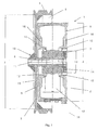
- a cable drive device 1 shown in Fig. 1 consists of a Hollow shaft motor 2 and one directly with the hollow shaft 3 of the hollow shaft motor. 2 via a connecting pin 4 connected pulley 5.
- the pulley 5 is a unilaterally open hollow cylinder 6, which has a larger inner diameter 7 than has the outer diameter 8 of the housing 9 of the hollow shaft motor 2, wherein on the closed end face 10 of the hollow cylinder 6 along the Rotation axis 11 of the pulley 5 a projecting into the hollow cylinder 6 Connecting pin 4 is arranged, the form-fitting manner in the hollow shaft. 3 engages so that the over the connecting pin 4 directly to the hollow shaft. 3 Connected sheave 5 the hollow shaft motor 2 frontally partially includes. Of the on the hub 15 of the pulley 5 fixed to this connected connecting pin 4 is in the hollow shaft 3 by means of a remote from the pulley 5 Front side of the hollow shaft motor 2 from accessible clamping set 14th recorded.
- the pulley 5 is completely over the bearing 12 of the hollow shaft 3 in the housing 9 of the hollow shaft motor 2 supported.
- the hollow shaft motor 2 has in particular, due to the large diameter 13 of the hollow shaft 3 a large dimensioned storage 12, so that acting on the pulley 5 outer Forces, such as the forces acting on the pulley 5 rope forces can be completely absorbed by the storage 12.
- the housing 9 of the hollow shaft motor 2 is a relation to the environment 16 and the interior 17 of the housing closed and with a not shown Cooling device or a heat exchanger connectable cooling channel 18 to Passing a cooling liquid arranged.
- integrated cooling channel 18 for the passage of coolant can the occurring in the hollow shaft motor 2 as heat dissipation effectively be discharged, so that the hollow shaft motor 2 at a low temperature can be operated permanently in the housing 9 at rated power.
- There one Cable drive device 1 usually with a pull-in speed of 15 Up to 75 m / min is operated, a liquid cooling is particularly suitable to the hollow shaft motor 2, the nominal torque at very low speed gives off, to cool.
- the hollow shaft motor can. 2 be operated indefinitely in this speed range.
- the pulley 5 a smaller inner diameter 7 than the outer diameter 8 of the housing 9 of the hollow shaft motor 2.
- the hollow cylindrical pulley 5 includes the Housing 9 of the hollow shaft motor 2 not, but is in the axial extension of the with the axis of rotation 11 of the pulley 5 identical longitudinal axis of the Hollow shaft 3 is arranged.
- the connecting pin 4 is on the of the Hollow cylinder 6 opposite side of the end face 10 of the hollow cylinder. 6 arranged.
- a cable drive device 1 shown in Fig. 3 is the hollow shaft motor 2 via a directly on the housing 9 arranged adapter 19 to a Base frame 20 mounted.
- the base frame is representative of one Foundation for installation of the cable drive device 1 on the basement floor, for the stiffening of a machine for making and / or processing a machine dry or wet web, or for the stationary support of a Such machine or components thereof.
- the hollow shaft motor 2 also directly without the Adapter 19 are attached to the base frame 20 by the housing 9 of the Hollow shaft motor 2 in the area that is not covered by the pulley 5, is attached to the base frame 20.
- the cable drive device 1 has with the hollow shaft motor 2 partially comprehensive pulley 5 a particular compact design with small outside dimensions, in which at all to the prior art previously required mechanical drive parts between Electric motor and pulley is omitted and so a special space-saving arrangement inside a machine for manufacturing and / or Processing a dry or wet material web is possible, thereby Design and construction of such a machine can be significantly simplified.
- a Tachometer 21 On the pulley 5 facing away from front side of the hollow shaft motor 2 is a Tachometer 21 arranged to indicate the speed of the hollow shaft motor. 2 and the pulley 5 and / or the peripheral speed of at least one via the pulley 5 driven web guide device.
- a cable drive device 1 is shown, which in particular for a Off-line coater is usable.
- the rope drive of an off-line coater Due to the long ropes, it requires a stronger wrap the pulley 5. To transfer the required power through the rope to be able to two pulleys 5 together with larger wrap, as needed for a single pulley 5.
- By arrangement of two identical rope drives 1 side by side on a common Base frame 20 can transmit the required drive power to the cable become. Due to the possible with hollow shaft motors 2, precise speed control is the abandonment of the previously required by the prior art transmission between only one electric motor 2 'and two sheaves 5, as in FIG. 5 shown, possible because a precise speed adjustment of the two Hollow shaft motors 2 is possible.
- the invention is particularly in the field of paper machine manufacturing and in the paper making industry.
Landscapes
- Engineering & Computer Science (AREA)
- Mechanical Engineering (AREA)
- Paper (AREA)
- Flexible Shafts (AREA)
- Connection Of Motors, Electrical Generators, Mechanical Devices, And The Like (AREA)
- Making Paper Articles (AREA)
Abstract
Description
- Fig. 1
- einen Querschnitt durch eine erfindungsgemäße Seilantriebsvorrichtung mit einer über einen Verbindungszapfen direkt mit der Hohlwelle eines Hohlwellenmotors verbundene, das Gehäuse des Hohlwellenmotors stirnseitig teilweise umfassenden Seilscheibe,
- Fig. 2
- einen Querschnitt durch eine erfindungsgemäße Seilantriebsvorrichtung mit einer über einen Verbindungszapfen direkt mit der Hohlwelle eines Hohlwellenmotors verbundene und einen kleineren Durchmesser als das Gehäuse des Hohlwellenmotors aufweisende Seilscheibe,
- Fig. 3
- einen Querschnitt durch eine über einen an dem Gehäuse des Hohlwellenmotors angeordneten Adapter auf einen Grundrahmen montierte, erfindungsgemäße Seilantriebsvorrichtung,
- Fig. 4
- eine Draufsicht auf zwei auf das selbe Seil wirkende und auf einem gemeinsamen Grundrahmen angeordnete, erfindungsgemäße Seilantriebsvorrichtungen, und
- Fig. 5
- eine perspektivische Ansicht eines Seilantriebs einer Off-line Streichmaschine nach dem Stand der Technik.
- 1
- Seilantriebsvorrichtung
- 2
- Hohlwellenmotor
- 2'
- Elektromotor
- 3
- Hohlwelle
- 4
- Verbindungszapfen
- 5
- Seilscheibe
- 6
- Hohlzylinder
- 7
- Innendurchmesser der Seilscheibe
- 8
- Außendurchmesser des Gehäuses des Hohlwellenmotors
- 9
- Gehäuse des Hohlwellenmotors
- 10
- Stirnseite des Hohlzylinders
- 11
- Rotationsachse der Seilscheibe
- 12
- Lagerung der Hohlwelle
- 13
- Durchmesser der Hohlwelle
- 14
- Spannsatz
- 15
- Nabe
- 16
- Umgebung
- 17
- Innenraum
- 18
- Kühlkanal
- 19
- Adapter
- 20
- Grundrahmen
- 21
- Tachometer
- 22
- Getriebe
Claims (10)
- Seilantriebsvorrichtung (1) mit mindestens einem Elektromotor und mindestens einer Seilscheibe (5) zum Antrieb mindestens einer rotierbar angeordneten Bahnführungsvorrichtung für eine trockene oder nasse, laufende Materialbahn über ein Seil,
dadurch gekennzeichnet, dass der Elektromotor ein Hohlwellenmotor (2) mit einem Gehäuse (9) und einem in dem Gehäuse (9) angeordneten und mit der Hohlwelle (3) verbundenen Rotor ist, wobei die Seilscheibe (5) durch einen an ihrer Nabe (15) angeordneten und formschlüssig in die Hohlwelle (3) greifenden Verbindungszapfen (4) direkt mit dem Hohlwellenmotor (2) verbunden ist. - Seilantriebsvorrichtung nach Anspruch 1,
dadurch gekennzeichnet, dass die Seilscheibe (5) vollständig über die Lagerung (12) der Hohlwelle (3) in dem Gehäuse (9) des Hohlwellenmotors (2) abgestützt ist. - Seilantriebsvorrichtung nach Anspruch 1 oder 2,
dadurch gekennzeichnet, dass die Seilscheibe (5) ein einseitig offener Hohlzylinder (6) ist, der einen größeren Innendurchmesser (7) als der Außendurchmesser (8) des Gehäuses (9) des Hohlwellenmotors (2) aufweist, wobei an der geschlossenen Stirnseite (10) des Hohlzylinders (6) entlang der Rotationsachse (11) der Seilscheibe (5) ein in den Hohlzylinder (6) hineinragender Verbindungszapfen (4) angeordnet ist, der formschlüssig in die Hohlwelle (3) hineingreift, so dass die über den Verbindungszapfen (4) direkt mit der Hohlwelle (3) verbundene Seilscheibe (5) den Hohlwellenmotor (2) stirnseitig teilweise umfasst. - Seilantriebsvorrichtung nach einem der Ansprüche 1 bis 3,
dadurch gekennzeichnet, dass die Seilscheibe (5) mindestens eine stirnseitige Kühlluftöffnung aufweist. - Seilantriebsvorrichtung nach einem der vorhergehenden Ansprüche,
dadurch gekennzeichnet, dass im oder am Gehäuse (9) des Hohlwellenmotors (2) mindestens ein gegenüber der Umgebung (16) und dem Innenraum (17) des Gehäuses (9) geschlossener und mit einer Kühlvorrichtung verbindbarer Kühlkanal (18) angeordnet ist. - Seilantriebsvorrichtung nach einem der vorhergehenden Ansprüche,
dadurch gekennzeichnet, dass auf der der Seilscheibe (5) abgewandten Stirnseite des Hohlwellenmotors (2) eine Anzeigevorrichtung (21) angeordnet ist, zum Anzeigen der Drehzahl des Hohlwellenmotors (2) und der Seilscheibe (5) und/oder der Umfangsgeschwindigkeit mindestens einer über die Seilscheibe (5) angetriebenen Bahnführungsvorrichtung. - Seilantriebsvorrichtung nach Anspruch 6,
dadurch gekennzeichnet, dass auf der der Seilscheibe (5) abgewandten Stirnseite des Hohlwellenmotors (2) eine einstellbare Drehzahlregelvorrichtung angeordnet ist. - Seilantriebsvorrichtung nach einem der vorhergehenden Ansprüche,
dadurch gekennzeichnet, dass der Hohlwellenmotor (2) ein Hohlwellen-Drehstrom-Asynchron-Motor oder ein Hohlwellen-Drehstrom-Synchron-Motor ist. - Seilantriebsvorrichtung nach einem der vorhergehenden Ansprüche,
dadurch gekennzeichnet, dass mehrere gleichartige Seilantriebsvorrichtungen (1) auf das selbe Seil wirkend anordbar sind. - Maschine zur Behandlung einer trockenen oder nassen Materialbahn, insbesondere aus Papier oder Karton, mit mindestens einer über ein Seil antreibbaren, rotierenden Bahnführungsvorrichtung,
gekennzeichnet durch mindestens eine an oder in der Maschine angeordnete und die Bahnführungsvorrichtung antreibende Seilantriebsvorrichtung (1) nach einem der vorhergehenden Ansprüche.
Applications Claiming Priority (2)
| Application Number | Priority Date | Filing Date | Title |
|---|---|---|---|
| DE102004013781 | 2004-03-20 | ||
| DE102004013781A DE102004013781A1 (de) | 2004-03-20 | 2004-03-20 | Seilantriebsvorrichtung |
Publications (2)
| Publication Number | Publication Date |
|---|---|
| EP1580317A1 true EP1580317A1 (de) | 2005-09-28 |
| EP1580317B1 EP1580317B1 (de) | 2008-05-21 |
Family
ID=34853993
Family Applications (1)
| Application Number | Title | Priority Date | Filing Date |
|---|---|---|---|
| EP05101489A Expired - Lifetime EP1580317B1 (de) | 2004-03-20 | 2005-02-28 | Seilantriebsvorrichtung mit Hohlwellenmotor |
Country Status (3)
| Country | Link |
|---|---|
| EP (1) | EP1580317B1 (de) |
| AT (1) | ATE396300T1 (de) |
| DE (2) | DE102004013781A1 (de) |
Cited By (1)
| Publication number | Priority date | Publication date | Assignee | Title |
|---|---|---|---|---|
| EP2835467A3 (de) * | 2013-08-09 | 2015-03-11 | KÜHNE + VOGEL Prozessautomatisierung Antriebstechnik GmbH | Kühlmittel als Wärmequelle |
Citations (2)
| Publication number | Priority date | Publication date | Assignee | Title |
|---|---|---|---|---|
| US1533194A (en) * | 1923-05-24 | 1925-04-14 | George D Kilberry | Paper-machine driving mechanism |
| EP1158188A1 (de) * | 2000-05-22 | 2001-11-28 | Voith Paper Patent GmbH | Antriebseinheit |
-
2004
- 2004-03-20 DE DE102004013781A patent/DE102004013781A1/de not_active Withdrawn
-
2005
- 2005-02-28 DE DE502005004161T patent/DE502005004161D1/de not_active Expired - Lifetime
- 2005-02-28 AT AT05101489T patent/ATE396300T1/de active
- 2005-02-28 EP EP05101489A patent/EP1580317B1/de not_active Expired - Lifetime
Patent Citations (2)
| Publication number | Priority date | Publication date | Assignee | Title |
|---|---|---|---|---|
| US1533194A (en) * | 1923-05-24 | 1925-04-14 | George D Kilberry | Paper-machine driving mechanism |
| EP1158188A1 (de) * | 2000-05-22 | 2001-11-28 | Voith Paper Patent GmbH | Antriebseinheit |
Cited By (1)
| Publication number | Priority date | Publication date | Assignee | Title |
|---|---|---|---|---|
| EP2835467A3 (de) * | 2013-08-09 | 2015-03-11 | KÜHNE + VOGEL Prozessautomatisierung Antriebstechnik GmbH | Kühlmittel als Wärmequelle |
Also Published As
| Publication number | Publication date |
|---|---|
| DE102004013781A1 (de) | 2005-10-06 |
| EP1580317B1 (de) | 2008-05-21 |
| ATE396300T1 (de) | 2008-06-15 |
| DE502005004161D1 (de) | 2008-07-03 |
Similar Documents
| Publication | Publication Date | Title |
|---|---|---|
| DE69909133T2 (de) | Aufzugsantrieb mit gegenläufigen rotoren | |
| DE69835806T2 (de) | Verfahren in einem aufzugsantrieb | |
| EP1902996A1 (de) | Fahrtreppe oder Fahrsteig mit Antrieb | |
| WO2019034677A1 (de) | Direktantrieb bei rollen, walzen und winden in der stahl/ne-industrie | |
| EP1790599A1 (de) | Maschine mit einem Vorzugsweise als Synchronmotor ausgeführten und zum Direktantrieb eines Wickelkerns einer Wickelrolle dienenden Elektromotors, insbesondere zur Verwendung in der Papierindustrie, und sich hierauf beziehendes Umbauverfahren | |
| DE29908433U1 (de) | Walze | |
| EP1580317B1 (de) | Seilantriebsvorrichtung mit Hohlwellenmotor | |
| EP2242583A1 (de) | Rollenmühle | |
| DE202008003913U1 (de) | Magnetkupplung | |
| DE102005045406B4 (de) | Verwendung eines elektromotorischen Direktantriebes als Antrieb einer kontinuierlichen Presse | |
| EP0302905B1 (de) | Antrieb einer filzleitwalze | |
| EP4265556A1 (de) | Antriebsmaschine für einen aufzug | |
| EP0775525A1 (de) | Drehmomentabstützung | |
| DE102009029877A1 (de) | Torquemotor mit Brems- und/oder Halteeinrichtung | |
| WO2004042897A1 (de) | Direktantrieb für einen zylinder | |
| DE102004061669A1 (de) | Druckmaschinenwalze sowie Druckmaschinenzylinder | |
| EP2801660A1 (de) | Antrieb und System mit zumindest einer angetriebenen Walze oder Extruderschnecke | |
| DE60203371T2 (de) | Anordnung für eine riemenantriebsvorrichtung | |
| DE2518753B2 (de) | Zweiträumige Schachtfördermaschine, insbesondere Ab- und Weiterteufhaspel | |
| EP2233637B1 (de) | Lagergetriebeeinheit für eine Papier- oder Kartonmaschine | |
| DE20000913U1 (de) | Getriebehebewerk | |
| DE102006060853A1 (de) | Walzenantriebseinheit | |
| DE102004001467A1 (de) | Maschine oder Maschinenabschnitt mit wenigstens einem vorzugsweise als Synchronmotor oder/und Aufsteckmotor ausgeführten und zum Direktantrieb eines Wickelkerns einer Wickelrolle oder zum Direktantrieb einer sonstigen Drehkomponente dienenden Elektromotor, insbesondere zur Verwendung in der Papierindustrie, und sich hierauf beziehendes Umbauverfahren | |
| DE102006037961A1 (de) | Vorrichtung und Verfahren zum Spannen einer endlosen Bahn | |
| WO2011137921A1 (de) | Pelletierpresse zur herstellung von pellets und verfahren zur herstellung einer pelletierpresse |
Legal Events
| Date | Code | Title | Description |
|---|---|---|---|
| PUAI | Public reference made under article 153(3) epc to a published international application that has entered the european phase |
Free format text: ORIGINAL CODE: 0009012 |
|
| AK | Designated contracting states |
Kind code of ref document: A1 Designated state(s): AT BE BG CH CY CZ DE DK EE ES FI FR GB GR HU IE IS IT LI LT LU MC NL PL PT RO SE SI SK TR |
|
| AX | Request for extension of the european patent |
Extension state: AL BA HR LV MK YU |
|
| 17P | Request for examination filed |
Effective date: 20060328 |
|
| AKX | Designation fees paid |
Designated state(s): AT BE BG CH CY CZ DE DK EE ES FI FR GB GR HU IE IS IT LI LT LU MC NL PL PT RO SE SI SK TR |
|
| RAP1 | Party data changed (applicant data changed or rights of an application transferred) |
Owner name: VOITH PATENT GMBH |
|
| GRAP | Despatch of communication of intention to grant a patent |
Free format text: ORIGINAL CODE: EPIDOSNIGR1 |
|
| GRAS | Grant fee paid |
Free format text: ORIGINAL CODE: EPIDOSNIGR3 |
|
| GRAA | (expected) grant |
Free format text: ORIGINAL CODE: 0009210 |
|
| AK | Designated contracting states |
Kind code of ref document: B1 Designated state(s): AT BE BG CH CY CZ DE DK EE ES FI FR GB GR HU IE IS IT LI LT LU MC NL PL PT RO SE SI SK TR |
|
| REG | Reference to a national code |
Ref country code: GB Ref legal event code: FG4D Free format text: NOT ENGLISH |
|
| REG | Reference to a national code |
Ref country code: CH Ref legal event code: EP |
|
| REF | Corresponds to: |
Ref document number: 502005004161 Country of ref document: DE Date of ref document: 20080703 Kind code of ref document: P |
|
| REG | Reference to a national code |
Ref country code: IE Ref legal event code: FG4D Free format text: LANGUAGE OF EP DOCUMENT: GERMAN |
|
| REG | Reference to a national code |
Ref country code: SE Ref legal event code: TRGR |
|
| PG25 | Lapsed in a contracting state [announced via postgrant information from national office to epo] |
Ref country code: SI Free format text: LAPSE BECAUSE OF FAILURE TO SUBMIT A TRANSLATION OF THE DESCRIPTION OR TO PAY THE FEE WITHIN THE PRESCRIBED TIME-LIMIT Effective date: 20080521 |
|
| PG25 | Lapsed in a contracting state [announced via postgrant information from national office to epo] |
Ref country code: ES Free format text: LAPSE BECAUSE OF FAILURE TO SUBMIT A TRANSLATION OF THE DESCRIPTION OR TO PAY THE FEE WITHIN THE PRESCRIBED TIME-LIMIT Effective date: 20080901 |
|
| NLV1 | Nl: lapsed or annulled due to failure to fulfill the requirements of art. 29p and 29m of the patents act | ||
| PG25 | Lapsed in a contracting state [announced via postgrant information from national office to epo] |
Ref country code: PL Free format text: LAPSE BECAUSE OF FAILURE TO SUBMIT A TRANSLATION OF THE DESCRIPTION OR TO PAY THE FEE WITHIN THE PRESCRIBED TIME-LIMIT Effective date: 20080521 Ref country code: NL Free format text: LAPSE BECAUSE OF FAILURE TO SUBMIT A TRANSLATION OF THE DESCRIPTION OR TO PAY THE FEE WITHIN THE PRESCRIBED TIME-LIMIT Effective date: 20080521 |
|
| PG25 | Lapsed in a contracting state [announced via postgrant information from national office to epo] |
Ref country code: IS Free format text: LAPSE BECAUSE OF FAILURE TO SUBMIT A TRANSLATION OF THE DESCRIPTION OR TO PAY THE FEE WITHIN THE PRESCRIBED TIME-LIMIT Effective date: 20080921 |
|
| REG | Reference to a national code |
Ref country code: IE Ref legal event code: FD4D |
|
| PG25 | Lapsed in a contracting state [announced via postgrant information from national office to epo] |
Ref country code: LT Free format text: LAPSE BECAUSE OF FAILURE TO SUBMIT A TRANSLATION OF THE DESCRIPTION OR TO PAY THE FEE WITHIN THE PRESCRIBED TIME-LIMIT Effective date: 20080521 Ref country code: CZ Free format text: LAPSE BECAUSE OF FAILURE TO SUBMIT A TRANSLATION OF THE DESCRIPTION OR TO PAY THE FEE WITHIN THE PRESCRIBED TIME-LIMIT Effective date: 20080521 Ref country code: DK Free format text: LAPSE BECAUSE OF FAILURE TO SUBMIT A TRANSLATION OF THE DESCRIPTION OR TO PAY THE FEE WITHIN THE PRESCRIBED TIME-LIMIT Effective date: 20080521 Ref country code: IE Free format text: LAPSE BECAUSE OF FAILURE TO SUBMIT A TRANSLATION OF THE DESCRIPTION OR TO PAY THE FEE WITHIN THE PRESCRIBED TIME-LIMIT Effective date: 20080521 |
|
| PG25 | Lapsed in a contracting state [announced via postgrant information from national office to epo] |
Ref country code: RO Free format text: LAPSE BECAUSE OF FAILURE TO SUBMIT A TRANSLATION OF THE DESCRIPTION OR TO PAY THE FEE WITHIN THE PRESCRIBED TIME-LIMIT Effective date: 20080521 Ref country code: PT Free format text: LAPSE BECAUSE OF FAILURE TO SUBMIT A TRANSLATION OF THE DESCRIPTION OR TO PAY THE FEE WITHIN THE PRESCRIBED TIME-LIMIT Effective date: 20081021 Ref country code: SK Free format text: LAPSE BECAUSE OF FAILURE TO SUBMIT A TRANSLATION OF THE DESCRIPTION OR TO PAY THE FEE WITHIN THE PRESCRIBED TIME-LIMIT Effective date: 20080521 |
|
| PLBE | No opposition filed within time limit |
Free format text: ORIGINAL CODE: 0009261 |
|
| STAA | Information on the status of an ep patent application or granted ep patent |
Free format text: STATUS: NO OPPOSITION FILED WITHIN TIME LIMIT |
|
| 26N | No opposition filed |
Effective date: 20090224 |
|
| PG25 | Lapsed in a contracting state [announced via postgrant information from national office to epo] |
Ref country code: EE Free format text: LAPSE BECAUSE OF FAILURE TO SUBMIT A TRANSLATION OF THE DESCRIPTION OR TO PAY THE FEE WITHIN THE PRESCRIBED TIME-LIMIT Effective date: 20080521 Ref country code: BG Free format text: LAPSE BECAUSE OF FAILURE TO SUBMIT A TRANSLATION OF THE DESCRIPTION OR TO PAY THE FEE WITHIN THE PRESCRIBED TIME-LIMIT Effective date: 20080821 |
|
| BERE | Be: lapsed |
Owner name: VOITH PATENT G.M.B.H. Effective date: 20090228 |
|
| PG25 | Lapsed in a contracting state [announced via postgrant information from national office to epo] |
Ref country code: IT Free format text: LAPSE BECAUSE OF FAILURE TO SUBMIT A TRANSLATION OF THE DESCRIPTION OR TO PAY THE FEE WITHIN THE PRESCRIBED TIME-LIMIT Effective date: 20080521 |
|
| PG25 | Lapsed in a contracting state [announced via postgrant information from national office to epo] |
Ref country code: MC Free format text: LAPSE BECAUSE OF NON-PAYMENT OF DUE FEES Effective date: 20090228 |
|
| REG | Reference to a national code |
Ref country code: CH Ref legal event code: PL |
|
| GBPC | Gb: european patent ceased through non-payment of renewal fee |
Effective date: 20090228 |
|
| PG25 | Lapsed in a contracting state [announced via postgrant information from national office to epo] |
Ref country code: CH Free format text: LAPSE BECAUSE OF NON-PAYMENT OF DUE FEES Effective date: 20090228 Ref country code: LI Free format text: LAPSE BECAUSE OF NON-PAYMENT OF DUE FEES Effective date: 20090228 |
|
| REG | Reference to a national code |
Ref country code: FR Ref legal event code: ST Effective date: 20091030 |
|
| PG25 | Lapsed in a contracting state [announced via postgrant information from national office to epo] |
Ref country code: BE Free format text: LAPSE BECAUSE OF NON-PAYMENT OF DUE FEES Effective date: 20090228 |
|
| PG25 | Lapsed in a contracting state [announced via postgrant information from national office to epo] |
Ref country code: FR Free format text: LAPSE BECAUSE OF NON-PAYMENT OF DUE FEES Effective date: 20090302 Ref country code: GB Free format text: LAPSE BECAUSE OF NON-PAYMENT OF DUE FEES Effective date: 20090228 |
|
| PG25 | Lapsed in a contracting state [announced via postgrant information from national office to epo] |
Ref country code: GR Free format text: LAPSE BECAUSE OF FAILURE TO SUBMIT A TRANSLATION OF THE DESCRIPTION OR TO PAY THE FEE WITHIN THE PRESCRIBED TIME-LIMIT Effective date: 20080822 |
|
| PG25 | Lapsed in a contracting state [announced via postgrant information from national office to epo] |
Ref country code: LU Free format text: LAPSE BECAUSE OF NON-PAYMENT OF DUE FEES Effective date: 20090228 |
|
| PGFP | Annual fee paid to national office [announced via postgrant information from national office to epo] |
Ref country code: SE Payment date: 20110214 Year of fee payment: 7 |
|
| PG25 | Lapsed in a contracting state [announced via postgrant information from national office to epo] |
Ref country code: HU Free format text: LAPSE BECAUSE OF FAILURE TO SUBMIT A TRANSLATION OF THE DESCRIPTION OR TO PAY THE FEE WITHIN THE PRESCRIBED TIME-LIMIT Effective date: 20081122 |
|
| PG25 | Lapsed in a contracting state [announced via postgrant information from national office to epo] |
Ref country code: TR Free format text: LAPSE BECAUSE OF FAILURE TO SUBMIT A TRANSLATION OF THE DESCRIPTION OR TO PAY THE FEE WITHIN THE PRESCRIBED TIME-LIMIT Effective date: 20080521 |
|
| PG25 | Lapsed in a contracting state [announced via postgrant information from national office to epo] |
Ref country code: CY Free format text: LAPSE BECAUSE OF FAILURE TO SUBMIT A TRANSLATION OF THE DESCRIPTION OR TO PAY THE FEE WITHIN THE PRESCRIBED TIME-LIMIT Effective date: 20080521 |
|
| REG | Reference to a national code |
Ref country code: SE Ref legal event code: EUG |
|
| PG25 | Lapsed in a contracting state [announced via postgrant information from national office to epo] |
Ref country code: SE Free format text: LAPSE BECAUSE OF NON-PAYMENT OF DUE FEES Effective date: 20120301 |
|
| PGFP | Annual fee paid to national office [announced via postgrant information from national office to epo] |
Ref country code: DE Payment date: 20130219 Year of fee payment: 9 Ref country code: FI Payment date: 20130213 Year of fee payment: 9 |
|
| PGFP | Annual fee paid to national office [announced via postgrant information from national office to epo] |
Ref country code: AT Payment date: 20130213 Year of fee payment: 9 |
|
| REG | Reference to a national code |
Ref country code: DE Ref legal event code: R119 Ref document number: 502005004161 Country of ref document: DE |
|
| REG | Reference to a national code |
Ref country code: AT Ref legal event code: MM01 Ref document number: 396300 Country of ref document: AT Kind code of ref document: T Effective date: 20140228 |
|
| PG25 | Lapsed in a contracting state [announced via postgrant information from national office to epo] |
Ref country code: FI Free format text: LAPSE BECAUSE OF NON-PAYMENT OF DUE FEES Effective date: 20140228 |
|
| REG | Reference to a national code |
Ref country code: DE Ref legal event code: R119 Ref document number: 502005004161 Country of ref document: DE Effective date: 20140902 |
|
| PG25 | Lapsed in a contracting state [announced via postgrant information from national office to epo] |
Ref country code: AT Free format text: LAPSE BECAUSE OF NON-PAYMENT OF DUE FEES Effective date: 20140228 |
|
| PG25 | Lapsed in a contracting state [announced via postgrant information from national office to epo] |
Ref country code: DE Free format text: LAPSE BECAUSE OF NON-PAYMENT OF DUE FEES Effective date: 20140902 |