EP1579986B1 - Gerät zum Andrücken von Isolationsplatten - Google Patents
Gerät zum Andrücken von Isolationsplatten Download PDFInfo
- Publication number
- EP1579986B1 EP1579986B1 EP05300201A EP05300201A EP1579986B1 EP 1579986 B1 EP1579986 B1 EP 1579986B1 EP 05300201 A EP05300201 A EP 05300201A EP 05300201 A EP05300201 A EP 05300201A EP 1579986 B1 EP1579986 B1 EP 1579986B1
- Authority
- EP
- European Patent Office
- Prior art keywords
- chamber
- pressure
- passage
- insulation
- primary
- Prior art date
- Legal status (The legal status is an assumption and is not a legal conclusion. Google has not performed a legal analysis and makes no representation as to the accuracy of the status listed.)
- Expired - Lifetime
Links
- 238000003825 pressing Methods 0.000 title claims description 5
- 239000006260 foam Substances 0.000 claims description 15
- 238000000034 method Methods 0.000 claims description 8
- 239000000463 material Substances 0.000 claims description 2
- 238000009413 insulation Methods 0.000 description 27
- 239000012528 membrane Substances 0.000 description 19
- 239000003292 glue Substances 0.000 description 7
- 230000002093 peripheral effect Effects 0.000 description 7
- 238000007789 sealing Methods 0.000 description 7
- 239000000853 adhesive Substances 0.000 description 5
- 230000001070 adhesive effect Effects 0.000 description 5
- 230000004888 barrier function Effects 0.000 description 4
- 229910052751 metal Inorganic materials 0.000 description 4
- 239000002184 metal Substances 0.000 description 4
- 238000006116 polymerization reaction Methods 0.000 description 3
- 239000004593 Epoxy Substances 0.000 description 2
- 229910001374 Invar Inorganic materials 0.000 description 2
- PXHVJJICTQNCMI-UHFFFAOYSA-N Nickel Chemical compound [Ni] PXHVJJICTQNCMI-UHFFFAOYSA-N 0.000 description 2
- 238000001816 cooling Methods 0.000 description 2
- 210000000003 hoof Anatomy 0.000 description 2
- 239000012212 insulator Substances 0.000 description 2
- 238000004519 manufacturing process Methods 0.000 description 2
- 239000011120 plywood Substances 0.000 description 2
- 238000011084 recovery Methods 0.000 description 2
- 229910000831 Steel Inorganic materials 0.000 description 1
- 238000004026 adhesive bonding Methods 0.000 description 1
- 239000002390 adhesive tape Substances 0.000 description 1
- 229910052782 aluminium Inorganic materials 0.000 description 1
- XAGFODPZIPBFFR-UHFFFAOYSA-N aluminium Chemical compound [Al] XAGFODPZIPBFFR-UHFFFAOYSA-N 0.000 description 1
- 230000000295 complement effect Effects 0.000 description 1
- 238000007796 conventional method Methods 0.000 description 1
- 238000000151 deposition Methods 0.000 description 1
- 238000001035 drying Methods 0.000 description 1
- 238000001704 evaporation Methods 0.000 description 1
- 230000008020 evaporation Effects 0.000 description 1
- 239000004744 fabric Substances 0.000 description 1
- 239000011521 glass Substances 0.000 description 1
- 238000010438 heat treatment Methods 0.000 description 1
- 238000003780 insertion Methods 0.000 description 1
- 230000037431 insertion Effects 0.000 description 1
- 229910052759 nickel Inorganic materials 0.000 description 1
- 238000011017 operating method Methods 0.000 description 1
- 239000004814 polyurethane Substances 0.000 description 1
- 229920002635 polyurethane Polymers 0.000 description 1
- 230000000750 progressive effect Effects 0.000 description 1
- 239000011347 resin Substances 0.000 description 1
- 229920005989 resin Polymers 0.000 description 1
- 229910001220 stainless steel Inorganic materials 0.000 description 1
- 239000010935 stainless steel Substances 0.000 description 1
- 239000010959 steel Substances 0.000 description 1
- 238000013022 venting Methods 0.000 description 1
Images



Classifications
-
- B—PERFORMING OPERATIONS; TRANSPORTING
- B30—PRESSES
- B30B—PRESSES IN GENERAL
- B30B1/00—Presses, using a press ram, characterised by the features of the drive therefor, pressure being transmitted directly, or through simple thrust or tension members only, to the press ram or platen
- B30B1/003—Presses, using a press ram, characterised by the features of the drive therefor, pressure being transmitted directly, or through simple thrust or tension members only, to the press ram or platen by an elastic bag or diaphragm expanded by fluid pressure
-
- B—PERFORMING OPERATIONS; TRANSPORTING
- B63—SHIPS OR OTHER WATERBORNE VESSELS; RELATED EQUIPMENT
- B63B—SHIPS OR OTHER WATERBORNE VESSELS; EQUIPMENT FOR SHIPPING
- B63B25/00—Load-accommodating arrangements, e.g. stowing, trimming; Vessels characterised thereby
- B63B25/02—Load-accommodating arrangements, e.g. stowing, trimming; Vessels characterised thereby for bulk goods
- B63B25/08—Load-accommodating arrangements, e.g. stowing, trimming; Vessels characterised thereby for bulk goods fluid
- B63B25/12—Load-accommodating arrangements, e.g. stowing, trimming; Vessels characterised thereby for bulk goods fluid closed
- B63B25/16—Load-accommodating arrangements, e.g. stowing, trimming; Vessels characterised thereby for bulk goods fluid closed heat-insulated
-
- B—PERFORMING OPERATIONS; TRANSPORTING
- B61—RAILWAYS
- B61D—BODY DETAILS OR KINDS OF RAILWAY VEHICLES
- B61D5/00—Tank wagons for carrying fluent materials
- B61D5/08—Covers or access openings; Arrangements thereof
-
- B—PERFORMING OPERATIONS; TRANSPORTING
- B63—SHIPS OR OTHER WATERBORNE VESSELS; RELATED EQUIPMENT
- B63B—SHIPS OR OTHER WATERBORNE VESSELS; EQUIPMENT FOR SHIPPING
- B63B3/00—Hulls characterised by their structure or component parts
- B63B3/14—Hull parts
- B63B3/68—Panellings; Linings, e.g. for insulating purposes
-
- F—MECHANICAL ENGINEERING; LIGHTING; HEATING; WEAPONS; BLASTING
- F17—STORING OR DISTRIBUTING GASES OR LIQUIDS
- F17C—VESSELS FOR CONTAINING OR STORING COMPRESSED, LIQUEFIED OR SOLIDIFIED GASES; FIXED-CAPACITY GAS-HOLDERS; FILLING VESSELS WITH, OR DISCHARGING FROM VESSELS, COMPRESSED, LIQUEFIED, OR SOLIDIFIED GASES
- F17C1/00—Pressure vessels, e.g. gas cylinder, gas tank, replaceable cartridge
- F17C1/12—Pressure vessels, e.g. gas cylinder, gas tank, replaceable cartridge with provision for thermal insulation
-
- F—MECHANICAL ENGINEERING; LIGHTING; HEATING; WEAPONS; BLASTING
- F17—STORING OR DISTRIBUTING GASES OR LIQUIDS
- F17C—VESSELS FOR CONTAINING OR STORING COMPRESSED, LIQUEFIED OR SOLIDIFIED GASES; FIXED-CAPACITY GAS-HOLDERS; FILLING VESSELS WITH, OR DISCHARGING FROM VESSELS, COMPRESSED, LIQUEFIED, OR SOLIDIFIED GASES
- F17C2203/00—Vessel construction, in particular walls or details thereof
- F17C2203/03—Thermal insulations
- F17C2203/0304—Thermal insulations by solid means
- F17C2203/0358—Thermal insulations by solid means in form of panels
-
- F—MECHANICAL ENGINEERING; LIGHTING; HEATING; WEAPONS; BLASTING
- F17—STORING OR DISTRIBUTING GASES OR LIQUIDS
- F17C—VESSELS FOR CONTAINING OR STORING COMPRESSED, LIQUEFIED OR SOLIDIFIED GASES; FIXED-CAPACITY GAS-HOLDERS; FILLING VESSELS WITH, OR DISCHARGING FROM VESSELS, COMPRESSED, LIQUEFIED, OR SOLIDIFIED GASES
- F17C2203/00—Vessel construction, in particular walls or details thereof
- F17C2203/06—Materials for walls or layers thereof; Properties or structures of walls or their materials
- F17C2203/0602—Wall structures; Special features thereof
- F17C2203/0612—Wall structures
- F17C2203/0626—Multiple walls
- F17C2203/0631—Three or more walls
-
- F—MECHANICAL ENGINEERING; LIGHTING; HEATING; WEAPONS; BLASTING
- F17—STORING OR DISTRIBUTING GASES OR LIQUIDS
- F17C—VESSELS FOR CONTAINING OR STORING COMPRESSED, LIQUEFIED OR SOLIDIFIED GASES; FIXED-CAPACITY GAS-HOLDERS; FILLING VESSELS WITH, OR DISCHARGING FROM VESSELS, COMPRESSED, LIQUEFIED, OR SOLIDIFIED GASES
- F17C2209/00—Vessel construction, in particular methods of manufacturing
- F17C2209/23—Manufacturing of particular parts or at special locations
- F17C2209/232—Manufacturing of particular parts or at special locations of walls
-
- F—MECHANICAL ENGINEERING; LIGHTING; HEATING; WEAPONS; BLASTING
- F17—STORING OR DISTRIBUTING GASES OR LIQUIDS
- F17C—VESSELS FOR CONTAINING OR STORING COMPRESSED, LIQUEFIED OR SOLIDIFIED GASES; FIXED-CAPACITY GAS-HOLDERS; FILLING VESSELS WITH, OR DISCHARGING FROM VESSELS, COMPRESSED, LIQUEFIED, OR SOLIDIFIED GASES
- F17C2221/00—Handled fluid, in particular type of fluid
- F17C2221/03—Mixtures
- F17C2221/032—Hydrocarbons
- F17C2221/033—Methane, e.g. natural gas, CNG, LNG, GNL, GNC, PLNG
-
- F—MECHANICAL ENGINEERING; LIGHTING; HEATING; WEAPONS; BLASTING
- F17—STORING OR DISTRIBUTING GASES OR LIQUIDS
- F17C—VESSELS FOR CONTAINING OR STORING COMPRESSED, LIQUEFIED OR SOLIDIFIED GASES; FIXED-CAPACITY GAS-HOLDERS; FILLING VESSELS WITH, OR DISCHARGING FROM VESSELS, COMPRESSED, LIQUEFIED, OR SOLIDIFIED GASES
- F17C2223/00—Handled fluid before transfer, i.e. state of fluid when stored in the vessel or before transfer from the vessel
- F17C2223/01—Handled fluid before transfer, i.e. state of fluid when stored in the vessel or before transfer from the vessel characterised by the phase
- F17C2223/0146—Two-phase
- F17C2223/0153—Liquefied gas, e.g. LPG, GPL
- F17C2223/0161—Liquefied gas, e.g. LPG, GPL cryogenic, e.g. LNG, GNL, PLNG
-
- F—MECHANICAL ENGINEERING; LIGHTING; HEATING; WEAPONS; BLASTING
- F17—STORING OR DISTRIBUTING GASES OR LIQUIDS
- F17C—VESSELS FOR CONTAINING OR STORING COMPRESSED, LIQUEFIED OR SOLIDIFIED GASES; FIXED-CAPACITY GAS-HOLDERS; FILLING VESSELS WITH, OR DISCHARGING FROM VESSELS, COMPRESSED, LIQUEFIED, OR SOLIDIFIED GASES
- F17C2223/00—Handled fluid before transfer, i.e. state of fluid when stored in the vessel or before transfer from the vessel
- F17C2223/03—Handled fluid before transfer, i.e. state of fluid when stored in the vessel or before transfer from the vessel characterised by the pressure level
- F17C2223/033—Small pressure, e.g. for liquefied gas
-
- F—MECHANICAL ENGINEERING; LIGHTING; HEATING; WEAPONS; BLASTING
- F17—STORING OR DISTRIBUTING GASES OR LIQUIDS
- F17C—VESSELS FOR CONTAINING OR STORING COMPRESSED, LIQUEFIED OR SOLIDIFIED GASES; FIXED-CAPACITY GAS-HOLDERS; FILLING VESSELS WITH, OR DISCHARGING FROM VESSELS, COMPRESSED, LIQUEFIED, OR SOLIDIFIED GASES
- F17C2270/00—Applications
- F17C2270/01—Applications for fluid transport or storage
- F17C2270/0102—Applications for fluid transport or storage on or in the water
- F17C2270/0105—Ships
- F17C2270/0107—Wall panels
Definitions
- the present invention relates to a device for pressurizing a bonded strip for the production of an insulating and sealed wall consisting of two layers of insulation: a primary layer and a secondary layer.
- walls consist of two successive sealing membranes, one primary in contact with the product contained in the tank and the other secondary disposed between the primary membrane and the carrier structure, these two membranes being alternated with two thermally insulating barriers .
- known walls consist of a primary foam insulation associated with a stainless steel primary membrane and a secondary foam insulation associated with a flexible secondary membrane comprising at least one thin continuous metal sheet such as for example an aluminum sheet sandwiched between two glass fabrics.
- Walls are also known whose two insulating layers are insulating caissons covered with INVAR or a 36% steel of nickel thermally stable between minus 200 ° C. and more than 400 ° C.
- These insulating and waterproof walls are made from a set of prefabricated panels comprising successively, between two rigid plates, the primary insulation, the secondary membrane and the secondary insulation.
- the primary membrane is then made on all the prefabricated panels covering the supporting structure.
- Each prefabricated panel has the general shape of a rectangular parallelepiped, the primary insulation element and the secondary insulation element respectively having, seen in plan, the shape of a first rectangle and a second rectangle whose sides are substantially parallel, the lengths and / or width of the first rectangle being smaller than those of the second rectangle to provide a peripheral flange.
- the peripheral flanges of adjacent panels and the sidewalls of the primary insulation elements define lanes, which may extend the entire length, width or height of the vessel.
- These corridors are filled to ensure the continuity of the seal formed by the panels before laying the primary membrane.
- the continuity of the primary insulating barrier is achieved by inserting pavers into the corridors.
- the peripheral edges are covered before the establishment of the pavers of a flexible web strip, comprising at least one continuous thin metal sheet.
- a conventional technique for producing sealing at the peripheral rims consists in depositing an epoxy or polyurethane-type adhesive on the peripheral rims, a flexible strip is unwound on the edges coated with glue and the strip is pressed by means of a manual press. During the polymerization phase of the adhesive, the flexible web is maintained at a pressure of about 0.1 or 0.2 bar depending on the type of resin.
- a known pressurizing system consists of an air cushion device sandwiched between the bonded flexible sheet web and a board which is attached to the upper rigid plate of the side panels of said aisle.
- the fixed position of the board is realized via force recovery bars fixed on the rigid plate via inserts already present for the subsequent fixation of the primary membrane.
- the panels do not systematically have an insert and therefore the use of this pressurizing device requires to drill and screw the stress recovery bars one by one and thus creating additional long and tedious operations.
- this device is in practice complex for a pressurization over a long length and long implementation.
- a device for performing the sealing of the secondary membrane where a continuous gluing apparatus comprising an adhesive strip covered with an epoxy or polyurethane type glue, a heating system for reactivating the glue, a glue system, Pressurization of the adhesive tape on the insulation and a cooling system for the glue taking.
- the pressurizing system consists of retractable rollers cooperating with a groove disposed in the upper part of each panel and pads pressurized by a jack.
- this device is to achieve a continuous seal by moving said device.
- this continuous bonding technique has the disadvantage of requiring a cooling system for the polymerization of the glue to prevent the immobilization of the apparatus throughout the duration of the drying of the glue which varies with the temperature ambient and which can last from 4 to 12 hours.
- the pressure is applied only on a limited part of the band.
- the object of the present invention is to provide a device that is both simple and effective to overcome the aforementioned drawbacks and which allows in particular an easier, faster and longer implementation in order to achieve faster continuity of the sealing of the secondary barrier to obtain an insulating and waterproof wall.
- the device according to the invention is a device for pressurizing a strip of flexible sheet bonded to the edges of two lateral structures, it is characterized in that the device comprises at least one sealed chamber comprising compressible walls and means evacuation of said chamber. Thanks to the compressible walls, during the evacuation of the sealed chamber, the height thereof is reduced steadily over its entire length and allows insertion without exerting direct pressure on the bonded strip. This configuration facilitates the positioning of the device since the chamber is under vacuum its height is lower than the atmospheric pressure, which allows to have play at height and allows to use the device regardless of different thicknesses of insulation web .
- the device is placed in a corridor and comprises retractable retaining means disposed on either side of the longitudinal axis of the corridor and cooperating with longitudinal grooves disposed on the side structures.
- retractable retaining means disposed on either side of the longitudinal axis of the corridor and cooperating with longitudinal grooves disposed on the side structures.
- the longitudinal grooves make it possible to receive retractable retaining elements such as lugs or pads or any other element complementary to said grooves, it is therefore not necessary to perforate the structures for holding the device.
- the device comprises a reference stop for the vertical positioning of said device in the corridor.
- This vertical positioning stop allows by a simple application of the pressurizing device in the corridor to directly put the holding means against the longitudinal grooves of the lateral structures which are thus exactly positioned for good cooperation.
- the retractable elements are two parallel longitudinal bars.
- the use of two bars Parallels gives a larger holding area for the device which is thus better held.
- the retractable elements are actuated by a system of rods.
- the links are rotatable about a central axis disposed in their middle while their ends are connected to retaining bars or clamping blades. The rotation of the rods in a direction of rotation causes the spacing of the blades to block the device and in the other direction their removal.
- the retractable elements are actuated by a system of hooves.
- the retaining bars or blades are placed on a support plate on which they can slide, their inner ends are beveled and two longitudinally sliding shoes each push out each of the blades to bring them into the groove the panel and perform the holding of the device in the hallway.
- the evacuation of the sealed chamber is performed by a venturi.
- the Venturi is simple and fast to make and use.
- the side walls of the sealed chamber are natural closed-cell foam.
- the height reduction of the sealed chamber during the evacuation is given by the density ratio of the foam and the internal pressure; when the air pressure is set, the chamber resumes its initial height in a non-abrupt manner and thus allows the application of a progressive and constant pressure on the glued strip.
- the method according to the invention implements a device positioned in the corridor where the pressure is exerted, the sealed chamber being evacuated with air and the pressurization is carried out by venting said chamber.
- the method uses at least two devices placed end to end in the corridor where it is desired to exert the pressure. It is thus possible to ensure a constant pressure on the pie the length of the corridor between the two panels to be sealed, and this regardless of the necessary pressurization time.
- a particular application of the invention is the pressurization of a bonded strip for the production of an insulating and leaktight wall of a vessel integrated in a carrier structure, in particular of a liquefied gas transport vessel, the vessel comprising two successive sealing membranes, one primary in contact with the product contained in the tank and the other secondary disposed between the primary membrane and the carrier structure, these two sealing membranes being alternated with two thermally insulating barriers, said wall insulating and waterproof being made from a set of prefabricated panels successively comprising, between two rigid plates, the primary insulation, the secondary membrane and the secondary insulation, each prefabricated panel has the general shape of a rectangular parallelepiped, primary insulation element and the secondary insulation element respectively having, in plan view, the shape of a first rectangle angle and a second rectangle whose sides are substantially parallel, the lengths and / or the width of the first rectangle being smaller than those of the second rectangle to provide a peripheral flange, said method comprising pressurizing a glued strip flexible ply comprising at least one thin continuous metal sheet on
- the device is particularly suitable for producing the seal of the secondary membrane between two prefabricated panels because it is necessary to maintain under pressure the strip of flexible sheet for a certain period, corresponding to the duration of polymerization of the adhesive, for example and at a certain pressure, from 0.1 to 0.2 bar approximately, distributed over the entire bonded surface.
- the prefabricated panel 1 (cf. figure 1 ) consists of a primary insulation 10 and a secondary insulation 11. Between the primary insulation 10 and the secondary insulation 11 is inserted a flexible or rigid secondary membrane 111 and having at least one thin continuous metal sheet .
- the primary insulation is covered with a plywood 102 which provides the superior rigidity of the panel 1.
- the secondary insulation 11 is bonded to a plywood 110 which provides the lower rigidity of the panel 1.
- a groove 103 is provided under the counter
- the primary insulation 10 is shorter and narrower than the secondary insulation 11 to create a space around the periphery. of panel 1 and creates a corridor 12 when two panels are arranged side by side.
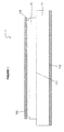
- the figure 2 shows two prefabricated panels 1 between which is placed an insulating seal 2 over the entire height of the secondary insulation 11.
- the primary insulation 10 being smaller than the secondary insulation 11, a corridor 12 separates the two primary insulators of the two panels 1.
- a strip of flexible ply 3 comprising at least one thin metallic sheet (here a) continuous is bonded astride the two secondary insulators 11 and the insulating seal 2.
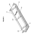
- the figures 3 and 4 illustrate the positioning of the device 4 in the corridor 12.
- the device 4 comprises a support plate 45, clamping blades 40 disposed on each side of the device 4, at least one pressing pad 41 (here two), at least one sealed chamber 42 (here two), referencing abutments 43, at least one air suction duct 44 connecting each sealed chamber 42 to the venturi or to a known vacuum system (not shown).
- the side walls 420 of each chamber 42 is constituted by a block of foam such as a closed-cell natural foam, the lower part of each chamber 42 is a longitudinal contact bar 421, the upper part 422 is a perforated wall of at least one hole 423 for the passage of the conduits 44.
- a contact foam 424 is placed under each chamber 42 under the contact bar 421, the contact bar assembly 421 and contact foam 424 then constituting the pressing pad 41.
- the chambers 42 are evacuated by a venturi (not shown) via the conduits 44 and holes 423. By evacuation of the chambers, the foam walls of said chambers are compress, thus for example during the evacuation a block of foam of 20cm high passes to 12-13 cm.
- the device 4 is inserted in the corridor 12, the reference stop 43 stops the device in height, the clamping blades 40 are spaced apart, they thus enter the grooves 103 to block the device 4.
- the chambers 42 are then brought to atmospheric pressure, which causes the descent of the entire pressing pad 41 by the resumption of the initial shape of the foam blocks 420. descent, the pad 41 and the foam 424 apply a constant pressure on the flexible sheet of tape 3 bonded previously to ensure the setting of the adhesive.
- the blades 40 are actuated by rods 400.
- Each rod 400 is rotatable in its middle 401 relative to the support plate 45 and at each of its ends 402 with each blade 40. In retracted position, the rods 400 have a certain angle relative to the longitudinal edges 450 of the support 45 and the blades 40 do not protrude from the support 45.
- the rotation of the rods 400 here in the counterclockwise direction, moves the blades 400 towards the outside of the support 45, the The blades 40 then protrude edges 450 and ensure the correct positioning of the device 4 by inserting the blades 40 into the grooves 104.
- This mode is particularly well suited for a constant corridor width.
- the blades 40 are pushed by shoes 403 sliding in the support plate 45. Each shoe slides in a not shown groove. By bringing the two shoes 403 closer to one another, the blades 40 are moved outwardly from the support 45 so as to insert them into the grooves 103.
- This arrangement has the advantage of a pressurizing device. which can be used for corridors of variable width.
Landscapes
- Engineering & Computer Science (AREA)
- Mechanical Engineering (AREA)
- Chemical & Material Sciences (AREA)
- Combustion & Propulsion (AREA)
- Ocean & Marine Engineering (AREA)
- Physics & Mathematics (AREA)
- Fluid Mechanics (AREA)
- General Engineering & Computer Science (AREA)
- Transportation (AREA)
- Filling Or Discharging Of Gas Storage Vessels (AREA)
- Press Drives And Press Lines (AREA)
Claims (10)
- Gerät (4) zur Druckbeaufschlagung eines Bandes aus weichem Auflagematerial (3), das auf die Ränder zweier seitlicher Strukturen (1) aufgeklebt ist, dadurch gekennzeichnet, dass das Gerät (4) mindestens eine dichte Kammer (42) umfasst, die kompressible Wände und Mittel zur Vakuumbeaufschlagung der dichten Kammer aufweist.
- Gerät (4) nach Anspruch 1, dadurch gekennzeichnet, dass das Gerät in einer Vertiefung (12) angeordnet ist, und dass es versenkbare Haltemittel (40) umfasst, die beiderseits der Längsachse der Vertiefung (12) angeordnet sind und mit Längsrillen (103) zusammenwirken, die auf den seitlichen Strukturen (1) angeordnet sind.
- Gerät (4) nach Anspruch 2, dadurch gekennzeichnet, dass es einen Bezugsanschlag (43) für die vertikale Positionierung des genannten Geräts in der Vertiefung (12) umfasst.
- Gerät (4) nach einem der Ansprüche 2 oder 3, dadurch gekennzeichnet, dass die versenkbaren Elemente (40) zwei parallele Längsstangen sind.
- Gerät (4) nach Anspruch 2 oder 4, dadurch gekennzeichnet, dass die versenkbaren Elemente (40) durch ein Schwingensystem (400) betätigt sind.
- Gerät (4) nach Anspruch 2 oder 4, dadurch gekennzeichnet, dass die versenkbaren Elemente (40) durch ein System von Schlitten (403) betätigt sind.
- Gerät (4) nach einem der vorhergehenden Ansprüche, dadurch gekennzeichnet, dass die Vakuumbeaufschlagung der Kammer (42) durch eine Venturidüse ausgeführt wird.
- Gerät (4) nach einem der vorhergehenden Ansprüche, dadurch gekennzeichnet, dass die seitlichen Wände (420) der dichten Kammer (42) aus reinem geschlossenporigen Schaumstoff bestehen.
- Verfahren zum Betreiben des Geräts (4) nach einem der vorausgehenden Ansprüche, dadurch gekennzeichnet, dass das Gerät (4) in die Vertiefung (12) gesetzt wird, wo der Druck ausgeübt wird, die dichte Kammer (42) luftleer gemacht wird und die Druckbeaufschlagung durch Anlegen der genannten Kammer (42) an die Atmosphäre durchgeführt wird.
- Verfahren zum Betreiben mindestens zweier Geräte (4) nach einem der Ansprüche 2 bis 8, dadurch gekennzeichnet, dass die Geräte (4) Ende an Ende in die Vertiefung (12) gebracht werden, wo man den Druck auszuüben wünscht.
Applications Claiming Priority (2)
| Application Number | Priority Date | Filing Date | Title |
|---|---|---|---|
| FR0450598A FR2868060B1 (fr) | 2004-03-26 | 2004-03-26 | Dispositif de mise sous pression de panneaux isolants |
| FR0450598 | 2004-03-26 |
Publications (2)
| Publication Number | Publication Date |
|---|---|
| EP1579986A1 EP1579986A1 (de) | 2005-09-28 |
| EP1579986B1 true EP1579986B1 (de) | 2008-11-19 |
Family
ID=34855232
Family Applications (1)
| Application Number | Title | Priority Date | Filing Date |
|---|---|---|---|
| EP05300201A Expired - Lifetime EP1579986B1 (de) | 2004-03-26 | 2005-03-21 | Gerät zum Andrücken von Isolationsplatten |
Country Status (7)
| Country | Link |
|---|---|
| EP (1) | EP1579986B1 (de) |
| JP (1) | JP4841853B2 (de) |
| KR (1) | KR101187176B1 (de) |
| CN (1) | CN100556667C (de) |
| DE (1) | DE602005011063D1 (de) |
| ES (1) | ES2315821T3 (de) |
| FR (1) | FR2868060B1 (de) |
Cited By (2)
| Publication number | Priority date | Publication date | Assignee | Title |
|---|---|---|---|---|
| CN104500489A (zh) * | 2014-11-28 | 2015-04-08 | 柳州威力士液压设备有限公司 | 液压缸 |
| WO2025083357A1 (fr) * | 2023-10-20 | 2025-04-24 | Gaztransport Et Technigaz | Système de plaquage d'une portion de membrane d'étanchéité d'une cuve de stockage |
Families Citing this family (8)
| Publication number | Priority date | Publication date | Assignee | Title |
|---|---|---|---|---|
| KR100553017B1 (ko) * | 2005-04-20 | 2006-02-15 | 이성욱 | 히팅패드를 이용한 2차 가스배리어 접착방법 |
| FR2893625B1 (fr) * | 2005-11-18 | 2008-01-25 | Chantiers De L Atlantique Sa | Procede de collage d'une bande de nappe souple sur un support |
| FR2897796B1 (fr) * | 2006-02-27 | 2010-06-11 | Chantiers De Latlantique | Procede pour eliminer un revetement, application et dispositifs le mettant en oeuvre |
| FR2911576B1 (fr) * | 2007-01-23 | 2009-03-06 | Alstom Sa | Procede de realisation d'une paroi isolante et etanche d'une cuve |
| KR101007697B1 (ko) * | 2008-05-30 | 2011-01-13 | 삼성중공업 주식회사 | 액화천연가스 운반선 내부의 화물창 2차 방벽 압착 장치 |
| KR101010337B1 (ko) * | 2008-12-05 | 2011-01-25 | 삼성중공업 주식회사 | 패널부착장치 |
| FR2942540B1 (fr) * | 2009-02-20 | 2011-04-29 | Hutchinson | Systeme et procede de verification de parametres de collage d'une barriere d'etancheite cryogenique |
| FR3085199B1 (fr) * | 2018-08-24 | 2020-07-17 | Gaztransport Et Technigaz | Paroi de cuve etanche et thermiquement isolante |
Family Cites Families (5)
| Publication number | Priority date | Publication date | Assignee | Title |
|---|---|---|---|---|
| US2600164A (en) * | 1946-12-21 | 1952-06-10 | Us Envelope Co | Vacuum gravity press |
| BE525893A (de) * | 1952-11-21 | |||
| JPS5790408A (en) * | 1980-11-21 | 1982-06-05 | Toppan Printing Co Ltd | Air cylinder |
| FR2822815B1 (fr) * | 2001-03-27 | 2003-10-31 | Gaz Transport & Technigaz | Machine pour le collage d'une bande, procede de collage d'une bande pour la realisation d'une paroi isolante et etanche, et paroi isolante et etanche |
| KR100557354B1 (ko) * | 2003-08-08 | 2006-03-06 | 삼성중공업 주식회사 | 액화천연가스 운반선의 단열방벽 시공방법 |
-
2004
- 2004-03-26 FR FR0450598A patent/FR2868060B1/fr not_active Expired - Fee Related
-
2005
- 2005-03-21 ES ES05300201T patent/ES2315821T3/es not_active Expired - Lifetime
- 2005-03-21 DE DE602005011063T patent/DE602005011063D1/de not_active Expired - Lifetime
- 2005-03-21 EP EP05300201A patent/EP1579986B1/de not_active Expired - Lifetime
- 2005-03-22 KR KR1020050023405A patent/KR101187176B1/ko not_active Expired - Fee Related
- 2005-03-24 JP JP2005085731A patent/JP4841853B2/ja not_active Expired - Fee Related
- 2005-03-28 CN CNB2005100588137A patent/CN100556667C/zh not_active Expired - Fee Related
Cited By (3)
| Publication number | Priority date | Publication date | Assignee | Title |
|---|---|---|---|---|
| CN104500489A (zh) * | 2014-11-28 | 2015-04-08 | 柳州威力士液压设备有限公司 | 液压缸 |
| WO2025083357A1 (fr) * | 2023-10-20 | 2025-04-24 | Gaztransport Et Technigaz | Système de plaquage d'une portion de membrane d'étanchéité d'une cuve de stockage |
| FR3154479A1 (fr) * | 2023-10-20 | 2025-04-25 | Gaztransport Et Technigaz | Système de plaquage d’une portion de membrane d’étanchéité d’une cuve de stockage |
Also Published As
| Publication number | Publication date |
|---|---|
| FR2868060B1 (fr) | 2006-06-09 |
| CN1672915A (zh) | 2005-09-28 |
| JP4841853B2 (ja) | 2011-12-21 |
| CN100556667C (zh) | 2009-11-04 |
| KR20060044505A (ko) | 2006-05-16 |
| KR101187176B1 (ko) | 2012-09-28 |
| JP2005289361A (ja) | 2005-10-20 |
| FR2868060A1 (fr) | 2005-09-30 |
| DE602005011063D1 (de) | 2009-01-02 |
| EP1579986A1 (de) | 2005-09-28 |
| ES2315821T3 (es) | 2009-04-01 |
Similar Documents
| Publication | Publication Date | Title |
|---|---|---|
| EP1579986B1 (de) | Gerät zum Andrücken von Isolationsplatten | |
| EP0573327B1 (de) | Vorgefertigte, flüssigkeitsdichtende und thermisch isolierende Wandstruktur für Behälter für cryogene Fluide | |
| EP0045257B1 (de) | Plattenwärmetauscher mit steifer Struktur | |
| EP2419671B3 (de) | Anschlag für eine sekundärmembran eines lng-tanks | |
| EP2114759A2 (de) | Verfahren zur herstellung einer isolierenden und festen wand für einen behälter | |
| FR2822815A1 (fr) | Machine pour le collage d'une bande, procede de collage d'une bande pour la realisation d'une paroi isolante et etanche, et paroi isolante et etanche | |
| FR2960470A1 (fr) | Procede de fabrication d'un raidisseur en materiau composite avec une section en omega | |
| FR2555501A1 (fr) | Procede de fabrication de structures rigides creuses en fibres impregnees de resine, dispositif pour sa mise en oeuvre et structure obtenue | |
| EP2283272A1 (de) | Leimbefestigung eines isolationsblocks für einen flüssiggasspeichertank unter verwendung wellender kügelchen | |
| EP3990882B1 (de) | Verfahren zum prüfen der abdichtung einer gedichteten membran | |
| FR2963273A1 (fr) | Procede de fabrication d'un panneau raidi en materiau composite | |
| FR2984381A1 (fr) | Systeme d'isolation thermique et procede d'assemblage associe. | |
| WO2020084247A1 (fr) | Cuve etanche et thermiquement isolante | |
| EP3018261B1 (de) | Vakuum-isolations-paneel (vip) mit wellen an der oberfläche, wandelement und wärmedämmwand, die ein solches paneel enthält | |
| FR2822814A1 (fr) | Machine pour le collage d'une bande, procede de collage d'une bande pour la realisation d'une paroi isolante et etanche, et paroi isolante et etanche | |
| FR3018719A1 (fr) | Procede de consolidation d'elements en materiau composite pour former une piece en materiau composite comprenant une cavite debouchante et noyau utilise pour la mise en oeuvre dudit procede | |
| WO2025083357A1 (fr) | Système de plaquage d'une portion de membrane d'étanchéité d'une cuve de stockage | |
| EP1968779B9 (de) | Verfahren zur klebeverbindung eines flexiblen textilstoffstreifens mit einem substrat | |
| FR2502311A1 (fr) | Absorbeur solaire en elastomere souple et son procede de fabrication | |
| EP4409192A1 (de) | Verfahren zur isolierung eines plattenzwischenraums | |
| FR2948156A1 (fr) | Outil de collage | |
| FR3092785A1 (fr) | procédé de formage d’un film d’ensachage sous vide comprenant la formation de nervures par flambage du film | |
| FR3152858A1 (fr) | Paroi de cuve étanche et thermiquement isolante comportant un joint isolant | |
| FR3015347A1 (fr) | Dispositif et procede de fabrication d'un panneau auto-raidi en materiau composite | |
| FR3164772A1 (fr) | Panneau prefabrique et cuve etanche et thermiquement isolante |
Legal Events
| Date | Code | Title | Description |
|---|---|---|---|
| PUAI | Public reference made under article 153(3) epc to a published international application that has entered the european phase |
Free format text: ORIGINAL CODE: 0009012 |
|
| AK | Designated contracting states |
Kind code of ref document: A1 Designated state(s): AT BE BG CH CY CZ DE DK EE ES FI FR GB GR HU IE IS IT LI LT LU MC NL PL PT RO SE SI SK TR |
|
| AX | Request for extension of the european patent |
Extension state: AL BA HR LV MK YU |
|
| RAP1 | Party data changed (applicant data changed or rights of an application transferred) |
Owner name: CHANTIERS DE L'ATLANTIQUE |
|
| 17P | Request for examination filed |
Effective date: 20060214 |
|
| AKX | Designation fees paid |
Designated state(s): DE ES FI FR IT |
|
| RAP1 | Party data changed (applicant data changed or rights of an application transferred) |
Owner name: AKER YARDS S.A. |
|
| GRAP | Despatch of communication of intention to grant a patent |
Free format text: ORIGINAL CODE: EPIDOSNIGR1 |
|
| GRAS | Grant fee paid |
Free format text: ORIGINAL CODE: EPIDOSNIGR3 |
|
| GRAA | (expected) grant |
Free format text: ORIGINAL CODE: 0009210 |
|
| AK | Designated contracting states |
Kind code of ref document: B1 Designated state(s): DE ES FI FR IT |
|
| REF | Corresponds to: |
Ref document number: 602005011063 Country of ref document: DE Date of ref document: 20090102 Kind code of ref document: P |
|
| REG | Reference to a national code |
Ref country code: ES Ref legal event code: FG2A Ref document number: 2315821 Country of ref document: ES Kind code of ref document: T3 |
|
| PLBE | No opposition filed within time limit |
Free format text: ORIGINAL CODE: 0009261 |
|
| STAA | Information on the status of an ep patent application or granted ep patent |
Free format text: STATUS: NO OPPOSITION FILED WITHIN TIME LIMIT |
|
| 26N | No opposition filed |
Effective date: 20090820 |
|
| REG | Reference to a national code |
Ref country code: FR Ref legal event code: PLFP Year of fee payment: 12 |
|
| PGFP | Annual fee paid to national office [announced via postgrant information from national office to epo] |
Ref country code: ES Payment date: 20160329 Year of fee payment: 12 Ref country code: DE Payment date: 20160316 Year of fee payment: 12 |
|
| PGFP | Annual fee paid to national office [announced via postgrant information from national office to epo] |
Ref country code: FI Payment date: 20160222 Year of fee payment: 12 |
|
| PGFP | Annual fee paid to national office [announced via postgrant information from national office to epo] |
Ref country code: IT Payment date: 20160317 Year of fee payment: 12 Ref country code: FR Payment date: 20160331 Year of fee payment: 12 |
|
| REG | Reference to a national code |
Ref country code: DE Ref legal event code: R119 Ref document number: 602005011063 Country of ref document: DE |
|
| PG25 | Lapsed in a contracting state [announced via postgrant information from national office to epo] |
Ref country code: FI Free format text: LAPSE BECAUSE OF NON-PAYMENT OF DUE FEES Effective date: 20170321 |
|
| REG | Reference to a national code |
Ref country code: FR Ref legal event code: ST Effective date: 20171130 |
|
| PG25 | Lapsed in a contracting state [announced via postgrant information from national office to epo] |
Ref country code: FR Free format text: LAPSE BECAUSE OF NON-PAYMENT OF DUE FEES Effective date: 20170331 Ref country code: DE Free format text: LAPSE BECAUSE OF NON-PAYMENT OF DUE FEES Effective date: 20171003 |
|
| PG25 | Lapsed in a contracting state [announced via postgrant information from national office to epo] |
Ref country code: IT Free format text: LAPSE BECAUSE OF NON-PAYMENT OF DUE FEES Effective date: 20170321 |
|
| REG | Reference to a national code |
Ref country code: ES Ref legal event code: FD2A Effective date: 20180706 |
|
| PG25 | Lapsed in a contracting state [announced via postgrant information from national office to epo] |
Ref country code: ES Free format text: LAPSE BECAUSE OF NON-PAYMENT OF DUE FEES Effective date: 20170322 |