EP1579924A1 - Ensemble de conditionnement et de distribution d'un produit fluide - Google Patents
Ensemble de conditionnement et de distribution d'un produit fluide Download PDFInfo
- Publication number
- EP1579924A1 EP1579924A1 EP05300195A EP05300195A EP1579924A1 EP 1579924 A1 EP1579924 A1 EP 1579924A1 EP 05300195 A EP05300195 A EP 05300195A EP 05300195 A EP05300195 A EP 05300195A EP 1579924 A1 EP1579924 A1 EP 1579924A1
- Authority
- EP
- European Patent Office
- Prior art keywords
- container
- storage chamber
- unit
- pump
- product
- Prior art date
- Legal status (The legal status is an assumption and is not a legal conclusion. Google has not performed a legal analysis and makes no representation as to the accuracy of the status listed.)
- Granted
Links
Images



Classifications
-
- B—PERFORMING OPERATIONS; TRANSPORTING
- B05—SPRAYING OR ATOMISING IN GENERAL; APPLYING FLUENT MATERIALS TO SURFACES, IN GENERAL
- B05B—SPRAYING APPARATUS; ATOMISING APPARATUS; NOZZLES
- B05B11/00—Single-unit hand-held apparatus in which flow of contents is produced by the muscular force of the operator at the moment of use
- B05B11/01—Single-unit hand-held apparatus in which flow of contents is produced by the muscular force of the operator at the moment of use characterised by the means producing the flow
- B05B11/10—Pump arrangements for transferring the contents from the container to a pump chamber by a sucking effect and forcing the contents out through the dispensing nozzle
- B05B11/1001—Piston pumps
- B05B11/1023—Piston pumps having an outlet valve opened by deformation or displacement of the piston relative to its actuating stem
-
- B—PERFORMING OPERATIONS; TRANSPORTING
- B05—SPRAYING OR ATOMISING IN GENERAL; APPLYING FLUENT MATERIALS TO SURFACES, IN GENERAL
- B05B—SPRAYING APPARATUS; ATOMISING APPARATUS; NOZZLES
- B05B11/00—Single-unit hand-held apparatus in which flow of contents is produced by the muscular force of the operator at the moment of use
- B05B11/0005—Components or details
- B05B11/0037—Containers
- B05B11/0054—Cartridges, i.e. containers specially designed for easy attachment to or easy removal from the rest of the sprayer
-
- A—HUMAN NECESSITIES
- A61—MEDICAL OR VETERINARY SCIENCE; HYGIENE
- A61N—ELECTROTHERAPY; MAGNETOTHERAPY; RADIATION THERAPY; ULTRASOUND THERAPY
- A61N2/00—Magnetotherapy
- A61N2/002—Magnetotherapy in combination with another treatment
-
- A—HUMAN NECESSITIES
- A61—MEDICAL OR VETERINARY SCIENCE; HYGIENE
- A61H—PHYSICAL THERAPY APPARATUS, e.g. DEVICES FOR LOCATING OR STIMULATING REFLEX POINTS IN THE BODY; ARTIFICIAL RESPIRATION; MASSAGE; BATHING DEVICES FOR SPECIAL THERAPEUTIC OR HYGIENIC PURPOSES OR SPECIFIC PARTS OF THE BODY
- A61H11/00—Belts, strips or combs for massage purposes
-
- A—HUMAN NECESSITIES
- A61—MEDICAL OR VETERINARY SCIENCE; HYGIENE
- A61H—PHYSICAL THERAPY APPARATUS, e.g. DEVICES FOR LOCATING OR STIMULATING REFLEX POINTS IN THE BODY; ARTIFICIAL RESPIRATION; MASSAGE; BATHING DEVICES FOR SPECIAL THERAPEUTIC OR HYGIENIC PURPOSES OR SPECIFIC PARTS OF THE BODY
- A61H39/00—Devices for locating or stimulating specific reflex points of the body for physical therapy, e.g. acupuncture
- A61H39/04—Devices for pressing such points, e.g. Shiatsu or Acupressure
-
- A—HUMAN NECESSITIES
- A61—MEDICAL OR VETERINARY SCIENCE; HYGIENE
- A61N—ELECTROTHERAPY; MAGNETOTHERAPY; RADIATION THERAPY; ULTRASOUND THERAPY
- A61N2/00—Magnetotherapy
- A61N2/06—Magnetotherapy using magnetic fields produced by permanent magnets
-
- B—PERFORMING OPERATIONS; TRANSPORTING
- B05—SPRAYING OR ATOMISING IN GENERAL; APPLYING FLUENT MATERIALS TO SURFACES, IN GENERAL
- B05B—SPRAYING APPARATUS; ATOMISING APPARATUS; NOZZLES
- B05B11/00—Single-unit hand-held apparatus in which flow of contents is produced by the muscular force of the operator at the moment of use
- B05B11/0005—Components or details
- B05B11/0037—Containers
- B05B11/0056—Containers with an additional opening for filling or refilling
-
- B—PERFORMING OPERATIONS; TRANSPORTING
- B05—SPRAYING OR ATOMISING IN GENERAL; APPLYING FLUENT MATERIALS TO SURFACES, IN GENERAL
- B05B—SPRAYING APPARATUS; ATOMISING APPARATUS; NOZZLES
- B05B11/00—Single-unit hand-held apparatus in which flow of contents is produced by the muscular force of the operator at the moment of use
- B05B11/01—Single-unit hand-held apparatus in which flow of contents is produced by the muscular force of the operator at the moment of use characterised by the means producing the flow
- B05B11/02—Membranes or pistons acting on the contents inside the container, e.g. follower pistons
- B05B11/028—Pistons separating the content remaining in the container from the atmospheric air to compensate underpressure inside the container
- B05B11/029—Pistons separating the content remaining in the container from the atmospheric air to compensate underpressure inside the container located on top of the remaining content
-
- A—HUMAN NECESSITIES
- A61—MEDICAL OR VETERINARY SCIENCE; HYGIENE
- A61H—PHYSICAL THERAPY APPARATUS, e.g. DEVICES FOR LOCATING OR STIMULATING REFLEX POINTS IN THE BODY; ARTIFICIAL RESPIRATION; MASSAGE; BATHING DEVICES FOR SPECIAL THERAPEUTIC OR HYGIENIC PURPOSES OR SPECIFIC PARTS OF THE BODY
- A61H2201/00—Characteristics of apparatus not provided for in the preceding codes
- A61H2201/10—Characteristics of apparatus not provided for in the preceding codes with further special therapeutic means, e.g. electrotherapy, magneto therapy or radiation therapy, chromo therapy, infrared or ultraviolet therapy
-
- A—HUMAN NECESSITIES
- A61—MEDICAL OR VETERINARY SCIENCE; HYGIENE
- A61H—PHYSICAL THERAPY APPARATUS, e.g. DEVICES FOR LOCATING OR STIMULATING REFLEX POINTS IN THE BODY; ARTIFICIAL RESPIRATION; MASSAGE; BATHING DEVICES FOR SPECIAL THERAPEUTIC OR HYGIENIC PURPOSES OR SPECIFIC PARTS OF THE BODY
- A61H2201/00—Characteristics of apparatus not provided for in the preceding codes
- A61H2201/16—Physical interface with patient
- A61H2201/1683—Surface of interface
- A61H2201/169—Physical characteristics of the surface, e.g. material, relief, texture or indicia
-
- A—HUMAN NECESSITIES
- A61—MEDICAL OR VETERINARY SCIENCE; HYGIENE
- A61N—ELECTROTHERAPY; MAGNETOTHERAPY; RADIATION THERAPY; ULTRASOUND THERAPY
- A61N5/00—Radiation therapy
- A61N5/06—Radiation therapy using light
- A61N2005/0658—Radiation therapy using light characterised by the wavelength of light used
- A61N2005/0659—Radiation therapy using light characterised by the wavelength of light used infrared
- A61N2005/066—Radiation therapy using light characterised by the wavelength of light used infrared far infrared
-
- B—PERFORMING OPERATIONS; TRANSPORTING
- B05—SPRAYING OR ATOMISING IN GENERAL; APPLYING FLUENT MATERIALS TO SURFACES, IN GENERAL
- B05B—SPRAYING APPARATUS; ATOMISING APPARATUS; NOZZLES
- B05B9/00—Spraying apparatus for discharge of liquids or other fluent material, without essentially mixing with gas or vapour
- B05B9/03—Spraying apparatus for discharge of liquids or other fluent material, without essentially mixing with gas or vapour characterised by means for supplying liquid or other fluent material
- B05B9/04—Spraying apparatus for discharge of liquids or other fluent material, without essentially mixing with gas or vapour characterised by means for supplying liquid or other fluent material with pressurised or compressible container; with pump
- B05B9/043—Spraying apparatus for discharge of liquids or other fluent material, without essentially mixing with gas or vapour characterised by means for supplying liquid or other fluent material with pressurised or compressible container; with pump having pump readily separable from container
Definitions
- the subject of the present invention is a set of conditioning and distribution of a product, including cosmetic, including care.
- cosmetic product is meant within the meaning of the present invention a product as defined in Directive 93/35 / EEC of 14 June 1993 amending Directive 76/768 / EEC.
- Patent application FR 2 773 443 discloses a rechargeable atomizer, having a body defining a chamber for storing a product.
- the atomizer further comprises a piston sliding in the body and recessable to reduce the volume of the room and distribute the product. According to the stroke stroke of the piston, a certain amount of product is dispensed, the chamber being completely emptied when the piston is depressed on a complete stroke.
- Atomizer does not allow dispensing easily and accurately a dose of product corresponding to a fraction of the volume maximum of the room.
- the patent application FR 2 705 039 describes a dispensing device having a container, containing a supply of product, provided with a first pump, and a refillable bottle with a second pump.
- the bottle can be refilled with produced through the first pump.
- the user separates the bottle from the container then actuates the second pump.
- Patent application FR 2 813 291 describes a filling system of a secondary bottle from a main bottle.
- the main bottle is equipped with cannulas allowing to put the main and secondary bottles in fluidic communication.
- the secondary bottle is equipped with a pump, the latter must be removed before the connection of the main and secondary bottles for refilling.
- the patent application FR 2 802 447 describes a vaporizer system rechargeable, comprising a reservoir and a vaporizer equipped with a pump.
- the reservoir and the vaporizer are provided with conduits that can be temporarily connected to allow the refilling of the vaporizer.
- the duct extending into the vaporizer is open at its upper end to allow product flow directly into the vaporizer reserve.
- Patent Application FR 2 556 091 describes a removable rechargeable device having a body and a piston sliding in the body. This device is devoid of pump.
- the present invention aims at providing a set of conditioning and distribution which has a relatively simple structure and allows for the distribution of relatively accurate way the product.
- the rechargeable unit when used separately from the container, it is possible to distribute relatively accurately one or more doses of product each corresponding to only a fraction of the maximum volume of the storage room.
- the amount of product corresponding to a dose is determined by the maximum volume of the pumping chamber, this maximum volume of the chamber of pumping being less than the maximum volume of the storage chamber.
- the pump can also be used to withdraw product from the storage tank. product of the container.
- the container When the receptacle has an outlet orifice capable of being fluidic communication with the storage chamber of the rechargeable unit for its filling, the container may be devoid of a pump capable of supplying the said product with outlet port.
- the container can thus have a relatively simple structure.
- the assembly according to the invention may comprise a single pump, that of the rechargeable unit, which reduces costs.
- the rechargeable unit is arranged to allow generating a depression in the storage chamber, at least when the storage chamber is in fluid communication with the container, so as to allow the filling of the storage room.
- This depression can be generated by means of the pump or other.
- the pumping chamber is isolated from the storage chamber at least during product dispensing by the pump.
- the pump comprises a suction port, which is adapted to be disposed near an outlet of the container, for example vertically above this outlet, when the refillable unit is arranged on the container.
- the product leaving the container through the outlet can flow to the suction port of the pump in a relatively short path, which limits the load losses.
- the pump is a pump without air intake. This pump can be with or without precompression.
- the container may comprise a support arranged to receive the unit rechargeable, said support being for example immobile relative to the rest of the container.
- the support can be an insert or be made monolithically with the container.
- the refillable unit and the container may have attachment portions respective adapted to cooperate detachably, in particular by snapping, screwing by a bayonet type fastener, by friction or otherwise. This can allow to secure the refill unit of the container during the filling of the chamber of storage and / or when the rechargeable unit pump is used to produced in the container.
- At least one of the refillable unit and the container has reliefs capable of cooperating with the other of the refillable unit and the container to seal the suction port of the pump from the outside.
- the container may include an air intake passage allowing recovery when the refill unit pump is used to draw product from the container.
- the container is without air intake and comprises in particular a piston or a pouch in contact with the product.
- the container may for example comprise a piston which moves in it in response to the departure of the product.
- the product may for example be contained in a flexible pouch.
- the storage chamber has a substantially constant volume.
- the rechargeable unit may comprise a first orifice capable of being fluid communication with the pump and the container to allow the pump to take the product into the container when the refill unit is placed on the container, and a second port distinct from the first, able to be ported fluidic with the container for filling the storage chamber.
- the second orifice can be made on a bottom wall of the unit rechargeable.
- the rechargeable unit may include a valve capable of isolating the orifice of the storage chamber when the refillable unit is arranged on the container, the latter being head up, and to allow fluid communication between said suction port and the storage chamber when the refillable unit is disposed on the container, the assembly being upside down.
- the rechargeable unit may comprise a wall, in particular a bottom wall, arranged to form with a wall of the container, when the refillable unit is disposed on the container, a passage outside the storage chamber.
- This passage can put in fluid communication the suction port of the pump with the chamber of storage. This passage can be closed by the aforementioned valve.
- the container may comprise a first outlet orifice adapted to be placed in fluidic communication with the first port of the rechargeable unit when the unit rechargeable battery is arranged on the container, and a second outlet port capable of being in fluid communication with the second port of the rechargeable unit when the refillable unit is disposed on the container.
- the container may comprise a valve capable of closing off the first orifice of out of the container when the set is upside down and release it when the container is head up.
- the refillable unit may comprise a body on which are made the first and second ports and a plug arranged to be removably attached to said body when the refillable unit is separated from the container, to close off said first and second orifices.
- the cap can form with the body of the rechargeable unit, when they are assembled, a passage, outside the storage chamber, between the first and second ports, making it possible to put the pump into fluid communication with the storage room.
- the cap can still define with the body of the rechargeable unit, when are assembled, an air intake passage allowing a return of air when the pump is used to take product from the storage chamber.
- the rechargeable unit has a body and a piston movable relative to the body and defining therewith a variable volume storage chamber.
- the volume of the chamber storage is minimal, being for example substantially zero.
- the storage chamber is formed under the piston, when the rechargeable unit is observed head up.
- the refillable unit may comprise a movable assembly with respect to said body, the moving assembly comprising the piston.
- the mobile assembly comprises a sliding outer sheath on the body.
- the moving assembly may also comprise a pump, which may comprise a conduit, the piston being fixed around said conduit.
- the piston presents advantageously a lower face set back from the lower end of the duct, this last having a portion extending downwardly under the piston.
- this suction port of the pump is made at the end lower part of the aforementioned conduit portion, this suction port is at a certain distance from the underside of the piston, allowing it to dive into the product contained in the storage chamber, including in the presence of a layer of air in the upper part of the storage chamber.
- the body of the refillable unit may include an orifice for in fluid communication the storage chamber with the container.
- the refillable unit may comprise a cap capable of being fixed in a manner removable, in particular by screwing or snapping, onto the body to close said orifice when the rechargeable unit is separated from the container.
- the container may contain a cosmetic product, including a care product, in particular a perfume.
- a cosmetic product including a care product, in particular a perfume.
- the product can still be a cream, for example.
- the rechargeable unit can be arranged to allow generating a depression in the storage chamber, at least when the storage chamber is in fluidic communication with the container, so as to allow the filling of the storage chamber under the effect of the depression thus created.
- the volume of the pumping chamber is preferably less than the volume maximum storage chamber.
- the storage chamber has a substantially constant volume.
- the rechargeable unit may comprise a first orifice capable of being fluid communication with the pump and the container to allow the pump to take the product into the container when the refill unit is placed on the container, and a second port distinct from the first, able to be ported fluidic with the container for filling the storage chamber.
- the rechargeable unit comprises a body and a movable piston to the body and defining therewith a storage chamber of variable volume.
- the storage chamber is located under the piston, when the rechargeable unit is observed head up.
- the pump may comprise a conduit, the piston being fixed around said conduit.
- the piston advantageously has a lower face set back from the lower end duct, the latter having a portion extending downwardly, under the piston.
- FIG. 1 shows a set of conditioning and distribution 1 according to the invention, comprising a container 2 for containing a reserve product and a rechargeable unit 3 arranged to be removably disposed on the container 2.
- the product is a cosmetic product, especially a perfume or other low viscosity product, for example containing a solvent alcoholic.
- the product may be a cream, for example a care cream, a milk or other product to be applied to any part of the body or face, including hair.
- the container 2 comprises a container body 4 provided at its end superior of a collar 6.
- the latter comprises a bead 7 allowing the attachment of a support 9 for receiving the rechargeable unit 3.
- the support 9 which can be made in a monolithic manner can comprise, as can be seen in FIG. 2, a mounting skirt 10 cooperating with the bead 7 of the 6.
- the mounting skirt 10 is snapped onto the neck 6 but, in Alternatively, it could be fixed otherwise, for example by screwing or crimping.
- At least one of the neck 6 or the support 9 may comprise, where appropriate, a means of anti-rotation, for example a relief (not shown), opposing the rotation of the support 9 with respect to the container 2.
- a means of anti-rotation for example a relief (not shown), opposing the rotation of the support 9 with respect to the container 2.
- the support 9 is provided with a sealing lip 11 coming to bear against the inner surface of the neck 6, to prevent the release of product, while providing a air intake passage 12 between the interior of the container 2 and the outside.
- the support 9 further comprises a substantially cylindrical wall 13, of axis X.
- This wall 13 extends substantially over the entire height of the support 9 inside the body 4 and is connected below a bottom wall 14 via a internally threaded portion 15.
- the wall 13 may have a circular cross section, elliptical or other.
- the walls 13 and 14 define inside the support 9 a housing 24 for receive the rechargeable unit 3.
- the bottom wall 14 carries on its underside a tip 16 serving the fixing a dip tube 17 and on its upper face a connection part 19 waterproof with the rechargeable unit 3.
- This connecting portion 19 defines a housing 18 communicating with a lower part with the plunger tube 17 through an opening 22 and secondly superiorly with the outside of the container 2 through a first outlet port 21.
- the housing 18 receives a ball 20 so as to form a flap capable to close the first outlet orifice 21 when the container 2 is upside down, as shown in Figure 4.
- the valve could have any other suitable shape without it is not within the scope of the present invention.
- This valve may allow, during removal of the rechargeable unit 3, to isolate the dip tube 17 from the outside, so that the product contained in the dip tube 17 can stay there.
- the bottom wall 14 has radially outside the part of connection 19 a second outlet 25 whose role will be explained later.
- the rechargeable unit 3 comprises a body 26 provided with a wall substantially cylindrical 27, X axis, connecting to a bottom wall 28.
- the wall 27 may present a circular, elliptical or other cross section.
- the body 26 has at its lower part a thread 29 intended to be screwed in the threaded portion 15 of the support 9 when the refill unit 3 is engaged in the housing 24 in a sealed manner.
- the bottom wall 28 externally has a recess 39 in which opens a first orifice 40 coming substantially opposite the first outlet orifice 21 of the container 2 when the rechargeable unit 3 is in place in the housing 24.
- the wall bottom 28 further comprises a second orifice 41, eccentric with respect to the axis X, coming substantially opposite the second outlet 25 of the container 2.
- the body 26 of the refillable unit 3 comprises in the lower part at least a relief 30a, such as for example an annular bead, adapted to apply 9.
- a relief 30b such as for example an annular bead, is made on the body 26 to apply substantially tightly on the part of 19.
- the orifices 21 and 40 are isolated from the outside by the reliefs 30a and 30b.
- the body 26 has, at its upper end, an annular bead 32 allowing the attachment of an insert 33 defining with the body 26 a storage chamber 35 of substantially constant volume.
- the insert 33 has a mounting skirt 36 cooperating with the bead 32 by snapping.
- the insert 33 could be fixed on the body 26 by screwing or crimping.
- the insert 33 further comprises a sealing lip 37 applied against the inner surface of the body 26 and a neck 38 for holding a pump 50, which is in the example considered conventional and without air intake.
- the pump 50 may comprise, as illustrated in FIG. 3, a body 51 fixed on the neck 38, for example by snapping.
- a control rod 52 is slidably mounted in the body 51 against the action of a return spring 53 working in compression.
- a tip 54 is attached to the lower end of the control rod 52.
- a push-button 55 serving both as an actuator and as an organ dispenser is force-fitted on the upper end of the control rod 52, as can be seen in Figure 2.
- the control rod 52 has an axial recess 58 extending up to its upper end and opening into the pumping chamber 57 through orifices radial 55.
- a piston 56 is arranged to slide around the rod 52, this piston 56 defining with the body 51 a pumping chamber 57.
- the body 51 forms a seat for a ball 59 closing at rest an orifice 60.
- the ball 59 remains in support against its seat in the bottom of the body 51 so as to isolate the pumping chamber 57 from the storage chamber 55.
- the axial recess 58 is then isolated from the pumping chamber 57 and the continuing the upward movement of the control rod 52 under the action of the spring 53 causes a depression in the pumping chamber 57, which is accompanied by lifting of the ball 59 and the suction of product in the pumping chamber 57.
- the pump 50 comprises a conduit 62 extending up to the bottom wall 28 of the body 26, this duct 62 having a suction port 63 opening at a very small distance from the first orifice 40.
- the conduit 62 is held at its lower end by a tip 65 se connecting to the bottom wall 28.
- the pump 50 may have a different structure without within the scope of the present invention, the ball 59 being able to be replaced by an elastomeric suction valve for example.
- the bottom wall 28 of the rechargeable unit 3 has, on its outer face, a groove 70 oriented radially and defining with the connecting portion 19 of the support 9 a passage 71, outside the storage chamber 35.
- This passage 71 allows the establishment of fluid communication between the suction port 63 of the pump 50 and the storage chamber 35, when the refillable unit 3 is in place on the container 2.
- the bottom wall 28 is connected inside the storage chamber 35 to tabs 73 defining a housing for a ball 72 capable of closing the passage 71 when the refillable unit 3 is disposed on the container 2, the latter being head up.
- Set 1 can be used in different ways.
- the set 1 can be used in a bathroom for example for taking and dispensing the product contained in the container 2.
- the user fixes the rechargeable unit 3 in the housing 24 of the container 2.
- the thread 29 of the refill unit 3 is engaged in the threaded portion 15 of the 9 and the reliefs 30a, 30b, are used to seal the orifices 21, 40, 25 and 41 from the outside.
- the assembly 1 is arranged upside down as illustrated in FIG. so that the ball 72 closes the passage 71.
- the suction port 63 of the pump 50 does not communicate with the storage chamber 35.
- the user actuates the pump 50 by pressing the pushbutton 55, which causes the distribution of the product present in the pumping chamber 57.
- the suction port 63 does not communicate with the storage chamber 35 but only with the supply of product in the container 2.
- the reliefs 30a and 30b isolate the suction orifice 63 from the outside, this which avoids a possible defusing of the pump.
- the rechargeable unit 3, previously recharged, can still be used separately from the container 2, and be carried in a purse for example.
- the user separates the refill unit 3 from the container 2 and fixes on the bottom wall 28 of the rechargeable unit 3 a plug 80, as illustrated in FIG.
- the plug 80 has a mounting skirt 81 allowing its screwing on the thread 19 of the body 26 and a projecting portion 82 engaging in the recess 39 of the body 26.
- the plug 80 also has a groove 83 defining with the wall of bottom 28 of the body 26 a passage 84 outside the storage chamber 35, allowing communicating the second orifice 41 with the first 40.
- An air intake passage 87 for the storage chamber 35 is defined in in addition between the plug 80 and the body 26.
- the user has the rechargeable unit 3 head up and actuates the pump 50, which allows the suction via the suction port 63 of product contained in the storage chamber 35, which flows along a path through the orifice 41, the passage 83 and the orifice 40.
- a hood not shown, for closing the outlet ports 21 and 25 of the container 2.
- This cover can for example be arranged to cap also the push button 55.
- the ball 72 releases the passage 71 and the suction port 63 of the pump 50 can communicate with the storage chamber 35, while the ball 20 closes the orifice 21 so as to isolate the suction port 63 from the pump 50 of the dip tube 17.
- the user actuates the pump 50, which makes it possible to evacuate the air in the storage chamber 35 and create a depression there. This causes the flow of the product of the container 2 in the storage chamber 35 through the orifices 25 and 41.
- the user can be warned of the end of the filling of the storage chamber When the actuation of the pump 50 causes the dispensing of product.
- the chamber of Storage of the rechargeable unit has a variable volume.
- the assembly 101 comprises a container 102 containing a reserve of product, especially a cream.
- the container 102 comprises a body 4 and a support 103 fixed on the body 4 and defining, like the support 9 previously described, a housing 104 for receive a refillable unit 105.
- the support 103 differs from the support 9 by the fact that it comprises a wall bottom 107 crossed by a single outlet orifice 108, which opens directly, without the intermediary of a valve, the plunger tube 17.
- the bottom wall 107 is connected by its upper face to a wall substantially cylindrical 110, into which the outlet orifice 108 opens.
- the support 103 has in the lower part an intermediate portion 112 connecting to the bottom wall 107, this intermediate portion 112 comprising internally a throat 113.
- the rechargeable unit 105 comprises a body 120 having a wall substantially cylindrical 121 of longitudinal axis X and a bottom wall 122.
- the wall 121 may have a circular cross section or other.
- a moving assembly 119 is movable relative to the body 120, which includes an outer sheath 123.
- the latter has on its inner surface, its lower end, first reliefs 125 adapted to cooperate with second reliefs 126 made at the upper end of the body 120 so as to form an abutment limiting the running up the sheath 123 relative to the body 120.
- This has at its lower end a tip 128 connecting to the bottom wall 122 and, extending around this end piece 128, a threaded mounting skirt 129 externally, whose role will be explained later.
- the end piece 128 comprises an annular sealing bead 130 suitable for apply sealingly against the wall 110 of the container 102.
- the end piece 128 is provided with an orifice 132 which is positioned at the right of the outlet orifice 108 of the container 2, at a small distance from it, or substantially when the refillable unit 105 is in place on the container 102, as shown in FIG. Figure 6.
- the body 120 of the rechargeable unit 105 comprises, at the lower end of the tubular wall 121, an annular bead 134 adapted to snap into the groove 113 of the support 103, in order to maintain the body 120 on the support 103, as will be explained further.
- the moving assembly 119 comprises a pump 150 without air intake, provided with internally of a pumping chamber.
- the pump 150 comprises a duct 151 provided with fixing reliefs 152 allowing the attachment of a piston 153 around the conduit 151.
- the lower face of the piston 153 is set back from the lower end of this conduit 151, the latter comprising a portion 158 extending downwardly under the piston 153, whose role will be specified more far.
- the piston 153 has two lower annular lips 156 and greater 157 bearing on the inner surface of the body 120 and defines with the body 120, under the piston 153, a storage chamber 155 of variable volume, as can be seen on Figures 7 and 8.
- the duct 151 moreover comprises over a major part of its height of longitudinal stiffening ribs 154 that can serve as a support for the upper face of the piston 153.
- the conduit portion 158 extending under the piston 153 has a bead annular 159 adapted to apply sealingly on the inner surface of the nozzle 132.
- the sheath 123 is provided at its upper end with a collar of gripping 160.
- the user In order to take and distribute the product contained in the container 102, the user introduces the rechargeable unit 105 in the housing 104 of the support 103, and depresses the moving assembly 119 to its end position, the suction port 63 of the pump 150 then being at the right of the orifices 108 and 132, at a distance substantially zero of the orifice 132.
- the annular bead 134 is then engaged in the 113 of the support 103. In this position, the orifices 108 and 132 are isolated from outside.
- product can flow from the dip tube 17 to the suction port 63 with reduced pressure drop.
- the mobile assembly 119 is not depressed to the end position in the body 120.
- the user To connect the conduit 151 to the outlet port 108, the user must push the movable assembly 119 to its end position, which causes the expulsion of the product contained in the storage chamber 155 to the container 102 to through the orifices 132 and 108 and the dip tube 17.
- the bead 130 is in sealing support against the wall 110 of the container 2, the bead 134 not being yet engaged in the groove 113.
- the portion of conduit 158 engages in the end piece 128, the volume of the storage chamber 155 then being minimal, being for example substantially zero.
- the establishment is completed by the engagement of the bead 134 in the throat 113. This commitment is felt by the user, which allows him to know that the implementation was carried out correctly.
- the user can take fixed product from the container 102, preferably upside down, actuating the pump 150.
- the user slides the mobile assembly 119 relative to the body 120, upwards, while pressing on the container 2 and pulling with its fingers the collar gripping 160.
- the cooperation of the annular bead 134 with the groove 113 ensures the maintenance of the body 120 on the support 103, against a predetermined, superior disengagement force to that exerted on this body 120 when the user slides upwards all 119.
- the body 120 remains secured to the support 103 when the moving assembly 119 is moved up.
- the volume of the storage chamber 155 increases; which creates in it a depression allowing the suction of product contained in the container 2 along a path through the dip tube 17 and the orifices 108 and 132.
- the user can separate the refill unit 105 from the support 103 of the container 102 by exerting on the body 120 a sufficient force to disengage the annular bead 134 from the groove 113.
- the product contained in the storage chamber 155 does not leak through the orifice 132 taking into account the surface tension of the product.
- the user After separation of the rechargeable unit 105 and the container 102, the user relates a cap 170 on the body 120.
- This cap 170 has a thread 171 cooperating with the mounting skirt 129 of the body 120, a sealing lip 172 and a pin central 174 intended to engage in the orifice 132 of the body 120.
- the plug may, alternatively, have another shape.
- the user actuates the pump 150.
- the pump 150 does not defuse even if a layer of air has accumulated under the piston 153, the suction port 63 can remain immersed in the product.
- the pump 150 being without air intake, the body 120 moves relative to the piston 153 as the product is dispensed, as shown in FIG. 8.
- a rechargeable unit can be used, for example the rechargeable unit 3 previously described, not with a single container 2 but with a plurality of containers 2 as illustrated in FIG. 9.
- the refillable unit 3 can be arranged temporarily on one of these containers 2 to allow the transfer of a certain amount of the product from the container 2 to the storage chamber of the rechargeable unit.
- Each of the containers 2 can thus contain, for example, a product corresponding to a particular scent, and the user can select one of the containers depending on the scent that he wants to use in the day.
- the user can also make a mixture of sampled products successively in several containers 2.
- the containers 2 can be sold separately from the refillable unit 3.
- FIG. 10 shows a set of conditioning and 300 distribution according to another example of implementation of the invention.
- This assembly 300 comprises a rechargeable unit 3 'substantially similar to that previously described.
- the rechargeable unit 3 ' may have a lower height and a section larger than the rechargeable unit 3.
- the refillable unit 3 ' can be recharged using a container 302 comprising a container body 303 with a neck 306 on which is fixed, for example by snap, a support 304.
- the support 304 comprises for example a tubular skirt 305 of X axis extending above the neck 306 of the container body 303 to receive the unit rechargeable 3 '.
- the support 304 has a bottom wall 310 substantially similar to the bottom wall 14 previously described, with the difference that the wall 310 is devoid of a nozzle for fixing the dip tube.
- the container 302 can be without air intake and comprise a piston or a pocket not shown, in contact with the product and to accompany the reduction of the volume of the supply of product contained in container 2 after each withdrawal of produced by the rechargeable unit.
Landscapes
- Health & Medical Sciences (AREA)
- Animal Behavior & Ethology (AREA)
- Veterinary Medicine (AREA)
- Public Health (AREA)
- General Health & Medical Sciences (AREA)
- Life Sciences & Earth Sciences (AREA)
- Rehabilitation Therapy (AREA)
- Physical Education & Sports Medicine (AREA)
- Pain & Pain Management (AREA)
- Epidemiology (AREA)
- Engineering & Computer Science (AREA)
- Biomedical Technology (AREA)
- Nuclear Medicine, Radiotherapy & Molecular Imaging (AREA)
- Radiology & Medical Imaging (AREA)
- Containers And Packaging Bodies Having A Special Means To Remove Contents (AREA)
- Closures For Containers (AREA)
- Basic Packing Technique (AREA)
- Filling Of Jars Or Cans And Processes For Cleaning And Sealing Jars (AREA)
Abstract
Description
- un récipient pour contenir une réserve de produit,
- une unité rechargeable agencée pour être disposée de façon amovible sur le
récipient, l'unité rechargeable comportant :
- une chambre de stockage pour contenir du produit et capable d'être mise en communication fluidique avec le récipient pour son remplissage lorsque l'unité rechargeable est disposée sur le récipient,
- une pompe capable de prélever du produit dans le récipient lorsque l'unité rechargeable est disposée dessus et de prélever du produit dans la chambre de stockage lorsque l'unité rechargeable est séparée du récipient, la pompe comportant une chambre de pompage distincte de la chambre de stockage, c'est-à-dire non confondue avec celle-ci.
- une chambre de stockage pour contenir du produit et capable d'être mise en communication fluidique avec le récipient pour son remplissage lorsque l'unité rechargeable est disposée sur le récipient,
- une pompe capable de prélever du produit dans le récipient lorsque l'unité rechargeable est disposée dessus et de prélever du produit dans la chambre de stockage lorsque l'unité rechargeable est séparée du récipient, la pompe comportant une chambre de pompage distincte de la chambre de stockage.
- fournir un ensemble de conditionnement et de distribution, comportant :
- un récipient pour contenir une réserve de produit,
- une unité rechargeable agencée pour être disposée de façon amovible sur le récipient et comportant une chambre de stockage et une pompe,
- prélever du produit à l'aide de l'unité rechargeable soit dans le récipient lorsque l'unité rechargeable est disposée sur le récipient, soit dans la chambre de stockage de l'unité rechargeable lorsque l'unité rechargeable est séparée du récipient,
- distribuer une dose de produit prélevée à l'aide de l'unité rechargeable en actionnant la pompe sur une course complète, la dose délivrée correspondant à une fraction seulement du volume maximal de la chambre de stockage, notamment à moins du dixième.
- mettre l'orifice d'aspiration en communication avec l'orifice de sortie,
- prélever du produit dans le récipient.
- disposer l'unité rechargeable sur le récipient, l'ensemble étant tête en bas,
- actionner la pompe à plusieurs reprises sur une course complète, pour créer une dépression dans la chambre de stockage et permettre le remplissage en produit de celle-ci, sans que le produit ne soit distribué entre deux courses complètes.
- disposer l'unité rechargeable sur le récipient,
- déplacer le piston relativement au corps afin d'augmenter le volume de la chambre de stockage, le piston étant lié fixement à la pompe lors de ce déplacement.
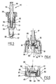
- la figure 1 représente, schématiquement et partiellement, un ensemble de conditionnement et de distribution conforme à l'invention,
- la figure 2 représente, schématiquement et partiellement, en coupe axiale, l'ensemble de la figure 1,
- la figure 3 représente, schématiquement et partiellement, en coupe axiale, la pompe de l'unité rechargeable de l'ensemble des figures 1 et 2,
- la figure 4 est une vue schématique et partielle, en coupe axiale, de l'ensemble de la figure 2, lors du remplissage de l'unité rechargeable,
- la figure 5 est une vue schématique et partielle, en coupe axiale, de l'unité rechargeable séparée du récipient,
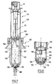
- la figure 6 représente, schématiquement et partiellement, en coupe axiale, un ensemble de conditionnement et de distribution conforme à un autre exemple de mise en oeuvre de l'invention,
- la figure 7 représente, schématiquement et partiellement, l'ensemble de la figure 6 en fin de remplissage,
- la figure 8 est une vue schématique et partielle, en coupe axiale, de l'unité rechargeable de l'ensemble des figures 6 et 7, séparée du récipient,
- la figure 9 représente, schématiquement et partiellement, un ensemble de conditionnement et de distribution conforme à un autre exemple de mise en oeuvre de l'invention, et
- la figure 10 représente, schématiquement et partiellement, en coupe axiale, un ensemble de conditionnement et de distribution conforme à un autre exemple de mise en oeuvre de l'invention.
Claims (46)
- Ensemble (1 ; 101 ; 201) de conditionnement et de distribution d'un produit, comportant :un récipient (2 ; 102 ; 302) pour contenir une réserve de produit,une unité rechargeable (3 ; 105 ; 3') agencée pour être disposée de façon amovible sur le récipient, l'unité rechargeable comportant :une chambre de stockage (35 ; 155) pour contenir du produit et capable d'être mise en communication fluidique avec le récipient pour son remplissage lorsque l'unité rechargeable est disposée sur le récipient,une pompe (50 ; 150) capable de prélever du produit dans le récipient lorsque l'unité rechargeable est disposée dessus et de prélever du produit dans la chambre de stockage (35 ; 155) lorsque l'unité rechargeable est séparée du récipient, la pompe comportant une chambre de pompage (57) distincte de la chambre de stockage (35 ; 155).
- Ensemble selon la revendication précédente, caractérisé par le fait que l'unité rechargeable (3 ; 3' ; 105) est agencée pour permettre de générer une dépression dans la chambre de stockage, au moins lorsque la chambre de stockage (35 ; 155) est en communication fluidique avec le récipient, de manière à permettre le remplissage de la chambre de stockage.
- Ensemble selon l'une des deux revendications précédentes, caractérisé par le fait que le récipient comporte un orifice de sortie (21 ; 132) apte à être mis en communication fluidique avec la chambre de stockage (35 ; 155) de l'unité rechargeable pour son remplissage, et par le fait que le récipient est dépourvu de pompe capable d'alimenter en produit ledit orifice de sortie (21 ; 132).
- Ensemble selon l'une quelconque des revendications précédentes, caractérisé par le fait que la chambre de pompage (57) est isolée de la chambre de stockage (35 ; 155) au moins lors de la distribution de produit par la pompe.
- Ensemble selon l'une quelconque des revendications précédentes, caractérisé par le fait que le volume de la chambre de pompage (57) est inférieur au volume maximal de la chambre de stockage (35 ; 155).
- Ensemble selon l'une quelconque des revendications précédentes, la pompe comportant un orifice d'aspiration (63), caractérisé par le fait que, lorsque l'unité rechargeable est disposée sur le récipient, ledit orifice d'aspiration (63) de la pompe (50 ; 150) est apte à être disposé à proximité d'un orifice de sortie (21 ; 132) du récipient, à l'aplomb de cet orifice de sortie.
- Ensemble selon l'une quelconque des revendications précédentes, caractérisé par le fait que la pompe (50 ; 150) est une pompe sans reprise d'air.
- Ensemble selon l'une quelconque des revendications précédentes, caractérisé par le fait que le récipient comporte un support (9 ; 103 ; 304) agencé pour recevoir l'unité rechargeable, ledit support (9 ; 103) étant immobile par rapport au reste du récipient.
- Ensemble selon l'une quelconque des revendications précédentes, caractérisé par le fait que l'unité rechargeable et le récipient comportent des parties de fixation (15, 29 ; 113, 134) respectives aptes à coopérer de manière amovible, notamment par encliquetage ou vissage.
- Ensemble selon l'une quelconque des revendications précédentes, caractérisé par le fait que l'un au moins de l'unité rechargeable et du récipient comporte des reliefs (30a ; 30b ; 111) aptes à coopérer avec l'autre de l'unité rechargeable et du récipient pour isoler de manière étanche l'orifice d'aspiration (63) de la pompe de l'extérieur.
- Ensemble selon l'une quelconque des revendications précédentes, caractérisé par le fait que le récipient comporte un passage de reprise d'air (12).
- Ensemble selon l'une quelconque des revendications 1 à 10, caractérisé par le fait que le récipient est sans reprise d'air.
- Ensemble selon l'une quelconque des revendications précédentes, caractérisé par le fait que la chambre de stockage (35) présente un volume sensiblement constant.
- Ensemble selon la revendication précédente, caractérisé par le fait que l'unité rechargeable (3) comporte un premier orifice (40) apte à être mis en communication fluidique avec la pompe (50) et le récipient (2) pour permettre à la pompe de prélever du produit dans le récipient lorsque l'unité rechargeable (3) est disposée sur le récipient, et un deuxième orifice (41) distinct du premier, apte à être mis en communication fluidique avec le récipient (2) pour le remplissage de la chambre de stockage.
- Ensemble selon la revendication précédente, caractérisé par le fait que le deuxième orifice (41) est réalisé sur une paroi de fond (28) de l'unité rechargeable.
- Ensemble selon l'une quelconque des revendications 13 à 15, la pompe comportant un orifice d'aspiration (63), caractérisé par le fait que l'unité rechargeable (3) comporte un clapet (72) capable d'isoler l'orifice d'aspiration (63) de la chambre de stockage (35) lorsque l'unité rechargeable (3) est disposée sur le récipient (2), ce dernier étant tête en haut, et de permettre une communication fluidique entre ledit orifice d'aspiration (63) et la chambre de stockage (35) lorsque l'unité rechargeable (3) est disposée sur le récipient (2), ce dernier étant tête en bas.
- Ensemble selon la revendication précédente, caractérisé par le fait que l'unité rechargeable (3) comporte une paroi, notamment une paroi de fond (28), agencée pour former, avec une paroi du récipient (19), lorsque l'unité rechargeable est disposée sur le récipient, un passage (71) à l'extérieur de la chambre de stockage (35), pouvant mettre en communication fluidique l'orifice d'aspiration (63) de la pompe avec la chambre de stockage (35), ce passage pouvant être obturé par ledit clapet (72).
- Ensemble selon la revendication 14 et éventuellement l'une quelconque des revendications 15 à 17, caractérisé par le fait que le récipient (2) comporte un premier orifice de sortie (21) apte à être mis en communication fluidique avec le premier orifice (40) de l'unité rechargeable (3) lorsque l'unité rechargeable est disposée sur le récipient, et un deuxième orifice de sortie (25) apte à être mis en communication fluidique avec le deuxième orifice (41) de l'unité rechargeable (3) lorsque l'unité rechargeable est disposée sur le récipient.
- Ensemble selon la revendication précédente, caractérisé par le fait que le récipient comporte un clapet (20) capable d'obturer ledit premier orifice de sortie (21) du récipient (2) lorsque le récipient est tête en bas, et de le libérer lorsque le récipient est tête en haut.
- Ensemble selon la revendication 14 et éventuellement l'une quelconque des revendications 15 à 19, caractérisé par le fait que l'unité rechargeable (3) comporte un corps (26) sur lequel sont réalisés les premier (40) et deuxième (41) orifices et un bouchon (80) agencé pour être fixé de manière amovible sur ledit corps (26) lorsque l'unité rechargeable (3) est séparée du récipient, afin d'obturer lesdits premier (40) et deuxième (41) orifices.
- Ensemble selon la revendication précédente, caractérisé par le fait que le bouchon (80) forme avec ledit corps (26), lorsqu'ils sont assemblés, un passage (84) à l'extérieur de la chambre de stockage entre les premier (40) et deuxième (41) orifices, permettant de mettre en communication fluidique la pompe (50) avec la chambre de stockage (35).
- Ensemble selon l'une des deux revendications précédentes, caractérisé par le fait que le bouchon (80) définit avec ledit corps (26), lorsqu'ils sont assemblés, un passage de reprise d'air.
- Ensemble selon l'une quelconque des revendications 1 à 12, caractérisé par le fait que l'unité rechargeable (105) comporte un corps (120) et un piston (153) mobile par rapport au corps (120) et définissant avec celui-ci une chambre de stockage de volume variable (155).
- Ensemble selon la revendication précédente, caractérisé par le fait que, lorsque l'unité rechargeable (105) est disposée sur le récipient (102) de manière à ce que la pompe puisse prélever du produit dans le récipient, la pompe communiquant notamment avec un tube plongeur (17) du récipient, le volume de la chambre de stockage (155) est minimal.
- Ensemble selon l'une des deux revendications précédentes, caractérisé par le fait que la chambre de stockage (155) est formée sous le piston (153), lorsque l'unité rechargeable est observée tête en haut.
- Ensemble selon la revendication précédente, caractérisé par le fait que l'unité rechargeable (105) comporte un ensemble mobile (119) par rapport au corps (120), l'ensemble mobile (119) comprenant le piston (153).
- Ensemble selon la revendication précédente, caractérisé par le fait que l'ensemble mobile (119) comporte un fourreau extérieur (123) coulissant sur le corps (120).
- Ensemble selon l'une des deux revendications précédentes, caractérisé par le fait que l'ensemble mobile (119) comporte une pompe (150).
- Ensemble selon la revendication précédente, caractérisé par le fait que la pompe (150) comporte un conduit (151), le piston (153) étant fixé autour dudit conduit.
- Ensemble selon la revendication précédente, caractérisé par le fait que le piston (153) présente une face inférieure en retrait de l'extrémité inférieure du conduit (151), ce dernier comportant une portion (158) se prolongeant vers le bas sous le piston (153).
- Ensemble selon l'une quelconque des revendications 25 à 30, caractérisé par le fait que le corps (120) de l'unité rechargeable (105) comporte un orifice (132) permettant de mettre en communication fluidique la chambre de stockage (155) avec le récipient (102).
- Ensemble selon la revendication précédente, caractérisé par le fait que l'unité rechargeable (105) comporte un bouchon (170) apte à être fixé de manière amovible, notamment par vissage ou encliquetage, sur le corps (120) pour obturer ledit orifice (132) lorsque l'unité rechargeable (105) est séparée du récipient (102).
- Ensemble selon l'une quelconque des revendications précédentes, caractérisé par le fait que le récipient contient un produit cosmétique, y compris de soin, notamment un parfum.
- Ensemble selon la revendication précédente, caractérisé par le fait que le produit est une crème.
- Unité rechargeable (3 ; 105) agencée pour être disposée de façon amovible sur un récipient, l'unité rechargeable comportant :une chambre de stockage (35 ; 155) pour contenir du produit et capable d'être mise en communication fluidique avec le récipient pour son remplissage lorsque l'unité rechargeable est disposée sur le récipient,une pompe (50 ; 150) capable de prélever du produit dans le récipient lorsque l'unité rechargeable est disposée dessus et de prélever du produit dans la chambre de stockage lorsque l'unité rechargeable est séparée du récipient, la pompe comportant une chambre de pompage (57) distincte de la chambre de stockage (35 ; 155).
- Unité rechargeable selon la revendication précédente, caractérisée par le fait qu'elle est agencée pour permettre de générer une dépression dans la chambre de stockage, au moins lorsque la chambre de stockage (35 ; 155) est en communication fluidique avec le récipient (2 ; 102 ; 3'), de manière à permettre le remplissage de la chambre de stockage sous l'effet de la dépression ainsi créée.
- Unité rechargeable selon l'une des deux revendications précédentes, caractérisée par le fait que le volume de la chambre de pompage (57) est inférieur au volume maximal de la chambre de stockage (35 ; 155).
- Unité rechargeable selon l'une quelconque des revendications 35 à 37, caractérisée par le fait que la chambre de stockage (35) présente un volume sensiblement constant.
- Unité rechargeable selon la revendication précédente, caractérisée par le fait qu'elle comporte un premier orifice (40) apte à être mis en communication fluidique avec la pompe (50) et le récipient (2) pour permettre à la pompe de prélever du produit dans le récipient lorsque l'unité rechargeable (3) est disposée sur le récipient, et un deuxième orifice (41) distinct du premier, apte à être mis en communication fluidique avec le récipient (2) pour le remplissage de la chambre de stockage.
- Unité rechargeable selon l'une des revendications 35 à 37, caractérisée par le fait qu'elle comporte un corps (120) et un piston (153) mobile par rapport au corps (120) et défmissant avec celui-ci une chambre de stockage de volume variable (155).
- Unité rechargeable selon la revendication précédente, caractérisée par le fait que la chambre de stockage (155) est située sous le piston (153), lorsque l'unité rechargeable est observée tête en haut.
- Unité rechargeable selon la revendication précédente, caractérisée par le fait que la pompe (150) comporte un conduit (151), le piston (153) étant fixé autour dudit conduit et par le fait que le piston (153) présente une face inférieure en retrait de l'extrémité inférieure du conduit (151), ce dernier comportant une portion (158) se prolongeant vers le bas sous le piston (153).
- Procédé de distribution d'un produit, comportant les étapes suivantes :fournir un ensemble (1 ; 101) de conditionnement et de distribution, comportant :un récipient (2 ; 102 ; 3') pour contenir une réserve de produit,une unité rechargeable (3 ; 105) agencée pour être disposée de façon amovible sur le récipient et comportant une chambre de stockage (35 ; 155) et une pompe (50 ; 150),prélever du produit à l'aide de l'unité rechargeable soit dans le récipient lorsque l'unité rechargeable est disposée sur le récipient, soit dans la chambre de stockage de l'unité rechargeable lorsque l'unité rechargeable est séparée du récipient,distribuer une dose de produit prélevée à l'aide de l'unité rechargeable en actionnant la pompe sur une course complète, la dose délivrée correspondant à une fraction seulement du volume maximal de la chambre de stockage, notamment à moins du dixième.
- Procédé selon la revendication précédente, la pompe comportant un orifice d'aspiration (63) et le récipient un orifice de sortie (21 ; 132), caractérisé par le fait que le procédé comporte les étapes suivantes :mettre l'orifice d'aspiration (63) en communication avec l'orifice de sortie (21 ; 132),prélever du produit dans le récipient.
- Procédé selon l'une des deux revendications précédentes, caractérisé par le fait qu'il comporte les étapes suivantes :disposer l'unité rechargeable (3) sur le récipient (2), l'ensemble étant tête en bas,actionner la pompe (50) à plusieurs reprises sur une course complète, pour créer une dépression dans la chambre de stockage et permettre le remplissage en produit de celle-ci, sans que le produit ne soit distribué entre deux courses complètes.
- Procédé selon la revendication 44, l'unité rechargeable comportant un corps et un piston coulissant dans le corps, caractérisé par le fait que le procédé comporte les étapes suivantes :disposer l'unité rechargeable (105) sur le récipient (102),déplacer le piston relativement au corps afin d'augmenter le volume de la chambre de stockage, le piston étant lié fixement à la pompe lors de ce déplacement.
Applications Claiming Priority (2)
| Application Number | Priority Date | Filing Date | Title |
|---|---|---|---|
| FR0403024A FR2868050B1 (fr) | 2004-03-24 | 2004-03-24 | Ensemble de conditionnement et de distribution d'un produit |
| FR0403024 | 2004-03-24 |
Publications (2)
| Publication Number | Publication Date |
|---|---|
| EP1579924A1 true EP1579924A1 (fr) | 2005-09-28 |
| EP1579924B1 EP1579924B1 (fr) | 2011-12-14 |
Family
ID=34855154
Family Applications (1)
| Application Number | Title | Priority Date | Filing Date |
|---|---|---|---|
| EP05300195A Expired - Lifetime EP1579924B1 (fr) | 2004-03-24 | 2005-03-18 | Ensemble de conditionnement et de distribution d'un produit fluide |
Country Status (9)
| Country | Link |
|---|---|
| US (1) | US7743949B2 (fr) |
| EP (1) | EP1579924B1 (fr) |
| JP (1) | JP4465292B2 (fr) |
| KR (1) | KR100646645B1 (fr) |
| CN (1) | CN100488641C (fr) |
| AT (1) | ATE536939T1 (fr) |
| BR (1) | BRPI0501144A (fr) |
| ES (1) | ES2379269T3 (fr) |
| FR (1) | FR2868050B1 (fr) |
Cited By (14)
| Publication number | Priority date | Publication date | Assignee | Title |
|---|---|---|---|---|
| WO2006122377A2 (fr) | 2005-05-18 | 2006-11-23 | Phillipe Kriwin | Dispositif de pulverisation pour parfum |
| EP2092985A1 (fr) * | 2008-02-25 | 2009-08-26 | Seriplast | Flacon comprenant un tube plongeur |
| WO2010083419A1 (fr) * | 2009-01-16 | 2010-07-22 | Colgate-Palmolive Company | Contenant de distribution comprenant une douille de réception de pompe |
| EP2335833A1 (fr) * | 2009-12-18 | 2011-06-22 | Rexam Dispensing Systems | Flacon de distribution d'un produit fluide comprenant une soupage de remplissage |
| WO2013011243A1 (fr) * | 2011-07-21 | 2013-01-24 | Aptar France Sas | Distributeur nomade rechargeable. |
| WO2014085875A1 (fr) * | 2012-12-06 | 2014-06-12 | Philippe Kriwin | Ensemble rechargeable x |
| FR3004429A1 (fr) * | 2013-04-16 | 2014-10-17 | Rexam Dispensing Sys | Ensemble comprenant un flacon remplissable et une source de produit |
| WO2014199094A1 (fr) * | 2013-06-14 | 2014-12-18 | Aptar France Sas | Reservoir de produit fluide rechargeable. |
| EP2977110A1 (fr) * | 2014-07-25 | 2016-01-27 | APTAR France SAS | Distributeur de produit fluide rechargeable |
| CN106061320A (zh) * | 2014-02-28 | 2016-10-26 | 克丽丝汀迪奥香水化妆品公司 | 用于材料补充器的封装设备 |
| FR3046945A1 (fr) * | 2016-01-25 | 2017-07-28 | Aptar France Sas | Distributeur de produit fluide rechargeable. |
| FR3064927A1 (fr) * | 2017-04-11 | 2018-10-12 | Aptar France Sas | Distributeur de produit fluide rechargeable. |
| CN114867681A (zh) * | 2019-11-07 | 2022-08-05 | 盼嘏篮株式会社 | 具备重复装填结构的便携式容器 |
| FR3133327A1 (fr) * | 2022-03-14 | 2023-09-15 | Cinqpats | Flacon-distributeur à pompe pour distribuer une composition fluide, après modification de son état physique, et application à un contenu comprenant une phase fluide continue et au moins une phase discontinue |
Families Citing this family (31)
| Publication number | Priority date | Publication date | Assignee | Title |
|---|---|---|---|---|
| FR2869302B1 (fr) * | 2004-04-21 | 2006-07-14 | Oreal | Ensemble de conditionnement et de distribution d'un produit, notamment cosmetique |
| FR2885890B1 (fr) * | 2005-05-20 | 2007-07-20 | Rexam Dispensing Systems Sas | Dispositif pour la delivrance et l'admission d'un produit liquide |
| CN201329329Y (zh) * | 2008-12-26 | 2009-10-21 | 东莞怡信磁碟有限公司 | 改进型便携可充式喷液瓶 |
| FR2949764B1 (fr) * | 2009-09-07 | 2011-11-25 | Maitrise & Innovation | Dispositif de distribution a diffuseur mobile et embase fixe comportant une pompe electrique miniature |
| JP5592306B2 (ja) * | 2011-05-11 | 2014-09-17 | 株式会社トキワ | 棒状化粧料繰出容器 |
| FR2976270B1 (fr) * | 2011-06-08 | 2013-06-28 | Rexam Dispensing Sys | Flacon de distribution d'un produit fluide |
| KR101287363B1 (ko) * | 2011-06-16 | 2013-07-19 | (주)톨리코리아 | 에어리스 펌프를 가지는 화장품용기의 도포장치 |
| CN102259714B (zh) * | 2011-07-26 | 2012-08-22 | 东莞怡信磁碟有限公司 | 一种便携式乳膏充液瓶 |
| FR2978742B1 (fr) * | 2011-08-01 | 2014-11-21 | Valois Sas | Distributeur de produit fluide. |
| MX349782B (es) * | 2011-08-02 | 2017-08-09 | Beauty Union Global Ltd | Atomizador portable y rellenable para crema. |
| US8695896B2 (en) * | 2011-11-23 | 2014-04-15 | Zhejiang Jm Industry Co., Ltd. | Perfume atomizer |
| CN103480525A (zh) * | 2012-06-11 | 2014-01-01 | 袁庆虞 | 名酒喷雾器 |
| CN104203771A (zh) * | 2012-07-25 | 2014-12-10 | 汇美环球有限公司 | 便携式可再填充的乳膏排出器 |
| FR2994867B1 (fr) * | 2012-09-04 | 2014-09-26 | Rexam Dispensing Sys | Flacon de distribution d’un produit fluide |
| FR2996829B1 (fr) * | 2012-10-15 | 2014-10-24 | Rexam Dispensing Sys | Flacon remplissable de distribution d’un produit fluide |
| US9365408B2 (en) * | 2012-11-16 | 2016-06-14 | Zhejiang Jm Industry Co., Ltd. | Auto refill perfume atomizer |
| FR3000944B1 (fr) * | 2013-01-11 | 2015-01-16 | Aptar France Sas | Distributeur de produit fluide. |
| FR3004624B1 (fr) * | 2013-04-22 | 2015-05-15 | Aptar France Sas | Distributeur de produit fluide. |
| CN103662363A (zh) * | 2013-12-10 | 2014-03-26 | 中山市联昌喷雾泵有限公司 | 一种优化主柱的乳液泵 |
| GB201413032D0 (en) * | 2014-02-28 | 2014-09-03 | Beyond Twenty Ltd | Beyond 7 |
| CN203819764U (zh) * | 2014-04-30 | 2014-09-10 | 东莞怡信磁碟有限公司 | 一种便携式乳膏瓶 |
| US20170127793A1 (en) * | 2014-07-02 | 2017-05-11 | Colgate-Palmolive Company | Refillable deodorant dispenser system, method, and kit |
| FR3027536B1 (fr) * | 2014-10-27 | 2016-12-23 | Aptar France Sas | Distributeur de produit fluide. |
| RU2671184C1 (ru) * | 2015-08-27 | 2018-10-29 | Деб АйПи Лимитед | Наливной шланг |
| CN107128588B (zh) * | 2017-06-26 | 2018-11-16 | 中山市意创科技研发有限公司 | 一种抽吸计量出液体的容器 |
| CN108741573B (zh) * | 2018-05-18 | 2021-02-12 | 上海川禾包装容器有限公司 | 一种护肤品瓶 |
| CN109573125B (zh) * | 2018-11-06 | 2020-12-04 | 上海壹维机电设备有限公司 | 一种大型助剂自动分配系统及分配方法 |
| IT202000027618A1 (it) * | 2020-11-18 | 2022-05-18 | Lumson Spa | Dispositivo di erogazione di una sostanza fluida |
| KR20230160013A (ko) | 2022-05-16 | 2023-11-23 | 삼성전자주식회사 | 액체 공급 장치 및 이를 포함하는 액체 공급 시스템 |
| US12350691B2 (en) * | 2022-12-02 | 2025-07-08 | Le Lu | Bottom-fillable spray bottle |
| CN118924016A (zh) | 2023-05-09 | 2024-11-12 | 深圳果德电子科技有限公司 | 液体分装瓶 |
Citations (4)
| Publication number | Priority date | Publication date | Assignee | Title |
|---|---|---|---|---|
| US3718165A (en) * | 1969-12-08 | 1973-02-27 | G Grothoff | Refillable aerosol dispenser |
| FR2430269A2 (fr) * | 1978-07-03 | 1980-02-01 | Normos Norbert | Tete de pulverisation amovible et rechargeable de type nouveau |
| FR2705039A1 (fr) * | 1993-05-10 | 1994-11-18 | Oreal | Dispositif de distribution d'une dose de volume déterminé d'un produit liquide ou pâteux. |
| US5894958A (en) * | 1997-01-22 | 1999-04-20 | L'oreal | Pressurized device with two valves |
Family Cites Families (11)
| Publication number | Priority date | Publication date | Assignee | Title |
|---|---|---|---|---|
| US4167941A (en) * | 1976-10-05 | 1979-09-18 | James D. Pauls, Ltd. (Limited Partnership) | Mechanically operated dispensing device for increasing discharge pressure and dispensing time |
| US4216882A (en) * | 1978-09-08 | 1980-08-12 | The Clorox Company | Bellows neck squeeze fluid dispenser |
| DE3116282A1 (de) | 1981-04-24 | 1982-11-11 | Henkel KGaA, 4000 Düsseldorf | "aerosol-verpackung" |
| FR2556091B1 (fr) | 1983-12-06 | 1986-10-03 | Oreal | Dispositif pour prelever une dose d'un produit liquide ou pateux |
| US4750532A (en) | 1986-12-11 | 1988-06-14 | Gisela Grothoff | Device for extracting liquids contained therein and arrangement for filling the device |
| DE59602418D1 (de) * | 1995-04-12 | 1999-08-19 | Wella Ag | Aufsatz zum Zumischen mindestens eines Produkts in Form mindestens eines Schaumstrangstreifens für einen Behälter zum Abgeben eines schaumförmigen Produkts |
| US5894960A (en) * | 1997-04-29 | 1999-04-20 | 3D Design And Engineering | Pump mechanism for mechanical dispensers |
| FR2773443B1 (fr) | 1998-01-12 | 2000-11-17 | Laetitia Carlotti | Atomiseur rechargeable de sac a main |
| FR2799449B1 (fr) | 1999-10-06 | 2001-12-14 | Oreal | Flacon doseur a pompe |
| FR2802447B1 (fr) | 1999-12-16 | 2002-02-15 | Lir France Sa | Systeme vaporisateur rechargeable |
| FR2813291A1 (fr) | 2000-08-30 | 2002-03-01 | Lir France Sa | Systeme de remplissage d'un flacon secondaire a partir d'un flacon principal |
-
2004
- 2004-03-24 FR FR0403024A patent/FR2868050B1/fr not_active Expired - Fee Related
-
2005
- 2005-02-24 US US11/065,137 patent/US7743949B2/en not_active Expired - Fee Related
- 2005-03-15 BR BRPI0501144-2A patent/BRPI0501144A/pt not_active IP Right Cessation
- 2005-03-18 EP EP05300195A patent/EP1579924B1/fr not_active Expired - Lifetime
- 2005-03-18 AT AT05300195T patent/ATE536939T1/de active
- 2005-03-18 ES ES05300195T patent/ES2379269T3/es not_active Expired - Lifetime
- 2005-03-23 CN CNB2005100569225A patent/CN100488641C/zh not_active Expired - Fee Related
- 2005-03-23 JP JP2005084205A patent/JP4465292B2/ja not_active Expired - Fee Related
- 2005-03-23 KR KR1020050023971A patent/KR100646645B1/ko not_active Expired - Fee Related
Patent Citations (4)
| Publication number | Priority date | Publication date | Assignee | Title |
|---|---|---|---|---|
| US3718165A (en) * | 1969-12-08 | 1973-02-27 | G Grothoff | Refillable aerosol dispenser |
| FR2430269A2 (fr) * | 1978-07-03 | 1980-02-01 | Normos Norbert | Tete de pulverisation amovible et rechargeable de type nouveau |
| FR2705039A1 (fr) * | 1993-05-10 | 1994-11-18 | Oreal | Dispositif de distribution d'une dose de volume déterminé d'un produit liquide ou pâteux. |
| US5894958A (en) * | 1997-01-22 | 1999-04-20 | L'oreal | Pressurized device with two valves |
Cited By (31)
| Publication number | Priority date | Publication date | Assignee | Title |
|---|---|---|---|---|
| WO2006122377A2 (fr) | 2005-05-18 | 2006-11-23 | Phillipe Kriwin | Dispositif de pulverisation pour parfum |
| EP2092985A1 (fr) * | 2008-02-25 | 2009-08-26 | Seriplast | Flacon comprenant un tube plongeur |
| FR2927888A1 (fr) * | 2008-02-25 | 2009-08-28 | Seriplast Soc Par Actions Simp | Flacon comprenant un tube plongeur |
| RU2469799C1 (ru) * | 2009-01-16 | 2012-12-20 | Колгейт-Палмолив Компани | Дозирующая емкость, содержащая установочный элемент для вмещения насоса |
| WO2010083419A1 (fr) * | 2009-01-16 | 2010-07-22 | Colgate-Palmolive Company | Contenant de distribution comprenant une douille de réception de pompe |
| US8434645B2 (en) | 2009-01-16 | 2013-05-07 | Colgate-Palmolive Company | Dispensing container with pump fitment |
| EP2409774A3 (fr) * | 2009-01-16 | 2013-05-29 | Colgate-Palmolive Company | Récipient d'administration comprenant un accessoire de réception de pompe |
| EP2409776A3 (fr) * | 2009-01-16 | 2013-05-29 | Colgate-Palmolive Company | Récipient d'administration comprenant un accessoire de réception de pompe |
| EP2335833A1 (fr) * | 2009-12-18 | 2011-06-22 | Rexam Dispensing Systems | Flacon de distribution d'un produit fluide comprenant une soupage de remplissage |
| FR2954292A1 (fr) * | 2009-12-18 | 2011-06-24 | Rexam Dispensing Sys | Flacon de distribution d'un produit fluide comprenant une soupape de remplissage |
| WO2013011243A1 (fr) * | 2011-07-21 | 2013-01-24 | Aptar France Sas | Distributeur nomade rechargeable. |
| FR2978130A1 (fr) * | 2011-07-21 | 2013-01-25 | Valois Sas | Distributeur nomade rechargeable. |
| US8739839B2 (en) | 2011-07-21 | 2014-06-03 | Aptar France S.A.S. | Refillable travel dispenser |
| WO2014085875A1 (fr) * | 2012-12-06 | 2014-06-12 | Philippe Kriwin | Ensemble rechargeable x |
| FR3004429A1 (fr) * | 2013-04-16 | 2014-10-17 | Rexam Dispensing Sys | Ensemble comprenant un flacon remplissable et une source de produit |
| US9469422B2 (en) | 2013-04-16 | 2016-10-18 | Albea Le Treport | Unit comprising a refillable bottle and a source of product |
| EP2792418A1 (fr) * | 2013-04-16 | 2014-10-22 | Albéa le Tréport | Ensemble comprenant un flacon remplissable et une source de produit |
| WO2014199094A1 (fr) * | 2013-06-14 | 2014-12-18 | Aptar France Sas | Reservoir de produit fluide rechargeable. |
| FR3007006A1 (fr) * | 2013-06-14 | 2014-12-19 | Aptar France Sas | Reservoir de produit fluide rechargeable. |
| CN106061320B (zh) * | 2014-02-28 | 2019-10-18 | 克丽丝汀迪奥香水化妆品公司 | 用于材料补充器的封装设备 |
| CN106061320A (zh) * | 2014-02-28 | 2016-10-26 | 克丽丝汀迪奥香水化妆品公司 | 用于材料补充器的封装设备 |
| EP2977110A1 (fr) * | 2014-07-25 | 2016-01-27 | APTAR France SAS | Distributeur de produit fluide rechargeable |
| FR3046945A1 (fr) * | 2016-01-25 | 2017-07-28 | Aptar France Sas | Distributeur de produit fluide rechargeable. |
| WO2017129883A1 (fr) * | 2016-01-25 | 2017-08-03 | Aptar France Sas | Distributeur de produit fluide rechargeable. |
| FR3064927A1 (fr) * | 2017-04-11 | 2018-10-12 | Aptar France Sas | Distributeur de produit fluide rechargeable. |
| WO2018189466A1 (fr) * | 2017-04-11 | 2018-10-18 | Aptar France Sas | Distributeur de produit fluide rechargeable. |
| US10850292B2 (en) | 2017-04-11 | 2020-12-01 | Aptar France Sas | Refillable fluid product dispenser |
| CN114867681A (zh) * | 2019-11-07 | 2022-08-05 | 盼嘏篮株式会社 | 具备重复装填结构的便携式容器 |
| CN114867681B (zh) * | 2019-11-07 | 2024-10-15 | 盼嘏篮株式会社 | 具备重复装填结构的便携式容器 |
| FR3133327A1 (fr) * | 2022-03-14 | 2023-09-15 | Cinqpats | Flacon-distributeur à pompe pour distribuer une composition fluide, après modification de son état physique, et application à un contenu comprenant une phase fluide continue et au moins une phase discontinue |
| WO2023175267A1 (fr) | 2022-03-14 | 2023-09-21 | Cinqpats | Flacon-distributeur à pompe d'une composition fluide après modification de son état physique, et application à un contenu comprenant une phase fluide continue et au moins une phase discontinue à éléments solides - au moins pour leur enveloppe -, disperses dans la phase fluide et devant être rompus |
Also Published As
| Publication number | Publication date |
|---|---|
| US7743949B2 (en) | 2010-06-29 |
| CN100488641C (zh) | 2009-05-20 |
| KR100646645B1 (ko) | 2006-11-23 |
| ATE536939T1 (de) | 2011-12-15 |
| JP4465292B2 (ja) | 2010-05-19 |
| US20050211731A1 (en) | 2005-09-29 |
| KR20060044608A (ko) | 2006-05-16 |
| BRPI0501144A (pt) | 2007-07-10 |
| CN1673049A (zh) | 2005-09-28 |
| EP1579924B1 (fr) | 2011-12-14 |
| JP2005272015A (ja) | 2005-10-06 |
| ES2379269T3 (es) | 2012-04-24 |
| FR2868050A1 (fr) | 2005-09-30 |
| FR2868050B1 (fr) | 2006-06-02 |
Similar Documents
| Publication | Publication Date | Title |
|---|---|---|
| EP1579924B1 (fr) | Ensemble de conditionnement et de distribution d'un produit fluide | |
| EP1588775B1 (fr) | Ensemble de conditionnement et de distribution d'un produit, notamment cosmétique | |
| EP1205400B1 (fr) | Récipient équipé d'un tube plongeur et d'un élément d'application | |
| EP0626210B1 (fr) | Dispositif de distribution d'une dose de volume déterminé d'un produit liquide ou pâteux | |
| EP3164033B1 (fr) | Distributeur de produit fluide | |
| EP3310491B1 (fr) | Système et procédé de re-remplissage en liquide d'un flacon | |
| EP0857149B1 (fr) | Distributeur de produits liquides ou pateux | |
| EP2301378B1 (fr) | Distributeur de produit cosmétique sur une surface de réception, dispositif de distribution et procédé associé | |
| FR2668958A1 (fr) | Dispositif de pulverisation ou de distribution de produit fluide, a aspiration du produit contenu dans le canal de sortie en fin d'actionnement. | |
| WO2013011243A1 (fr) | Distributeur nomade rechargeable. | |
| EP2926914B1 (fr) | Procédé d'extraction de liquide d'un appareil de distribution de liquide par injection de gaz | |
| WO2014096722A1 (fr) | Distributeur de produit fluide rechargeable | |
| EP1514492A1 (fr) | Dispositif de conditionnement et de distribution d'un produit cosmétique. | |
| FR2854131A1 (fr) | Procede de remplissage de reservoir de produit fluide, ensemble de remplissage de produit fluide et source de remplissage | |
| EP2703091A1 (fr) | Flacon de distribution d'un produit fluide | |
| EP1626813A2 (fr) | Distributeur de produit fluide et procede de montage d'un tel distributeur | |
| EP2838667B1 (fr) | Reservoir de produit fluide et distributeur utilisant un tel reservoir. | |
| EP2977110B1 (fr) | Distributeur de produit fluide rechargeable | |
| FR2886633A1 (fr) | Distributeur de produit fluide et procede de remplissage d'un tel distributeur | |
| WO1999034930A1 (fr) | Atomiseur rechargeable | |
| EP3953054B1 (fr) | Distributeur de produit fluide rechargeable | |
| EP3490406A1 (fr) | Dispositif de prelevement et d'application de produit fluide | |
| FR3120290A1 (fr) | Ensemble de conditionnement et de distribution d’un produit cosmétique et nécessaire associé | |
| FR3046945A1 (fr) | Distributeur de produit fluide rechargeable. | |
| EP2703090B1 (fr) | Flacon de distribution d'un produit fluide |
Legal Events
| Date | Code | Title | Description |
|---|---|---|---|
| PUAI | Public reference made under article 153(3) epc to a published international application that has entered the european phase |
Free format text: ORIGINAL CODE: 0009012 |
|
| 17P | Request for examination filed |
Effective date: 20050326 |
|
| AK | Designated contracting states |
Kind code of ref document: A1 Designated state(s): AT BE BG CH CY CZ DE DK EE ES FI FR GB GR HU IE IS IT LI LT LU MC NL PL PT RO SE SI SK TR |
|
| AX | Request for extension of the european patent |
Extension state: AL BA HR LV MK YU |
|
| AKX | Designation fees paid |
Designated state(s): AT BE BG CH CY CZ DE DK EE ES FI FR GB GR HU IE IS IT LI LT LU MC NL PL PT RO SE SI SK TR |
|
| 17Q | First examination report despatched |
Effective date: 20091014 |
|
| GRAP | Despatch of communication of intention to grant a patent |
Free format text: ORIGINAL CODE: EPIDOSNIGR1 |
|
| GRAS | Grant fee paid |
Free format text: ORIGINAL CODE: EPIDOSNIGR3 |
|
| GRAA | (expected) grant |
Free format text: ORIGINAL CODE: 0009210 |
|
| AK | Designated contracting states |
Kind code of ref document: B1 Designated state(s): AT BE BG CH CY CZ DE DK EE ES FI FR GB GR HU IE IS IT LI LT LU MC NL PL PT RO SE SI SK TR |
|
| REG | Reference to a national code |
Ref country code: GB Ref legal event code: FG4D Free format text: NOT ENGLISH |
|
| REG | Reference to a national code |
Ref country code: CH Ref legal event code: EP |
|
| REG | Reference to a national code |
Ref country code: IE Ref legal event code: FG4D |
|
| REG | Reference to a national code |
Ref country code: DE Ref legal event code: R096 Ref document number: 602005031634 Country of ref document: DE Effective date: 20120209 |
|
| REG | Reference to a national code |
Ref country code: NL Ref legal event code: VDEP Effective date: 20111214 |
|
| REG | Reference to a national code |
Ref country code: ES Ref legal event code: FG2A Ref document number: 2379269 Country of ref document: ES Kind code of ref document: T3 Effective date: 20120424 |
|
| PG25 | Lapsed in a contracting state [announced via postgrant information from national office to epo] |
Ref country code: LT Free format text: LAPSE BECAUSE OF FAILURE TO SUBMIT A TRANSLATION OF THE DESCRIPTION OR TO PAY THE FEE WITHIN THE PRESCRIBED TIME-LIMIT Effective date: 20111214 |
|
| LTIE | Lt: invalidation of european patent or patent extension |
Effective date: 20111214 |
|
| PG25 | Lapsed in a contracting state [announced via postgrant information from national office to epo] |
Ref country code: SE Free format text: LAPSE BECAUSE OF FAILURE TO SUBMIT A TRANSLATION OF THE DESCRIPTION OR TO PAY THE FEE WITHIN THE PRESCRIBED TIME-LIMIT Effective date: 20111214 Ref country code: GR Free format text: LAPSE BECAUSE OF FAILURE TO SUBMIT A TRANSLATION OF THE DESCRIPTION OR TO PAY THE FEE WITHIN THE PRESCRIBED TIME-LIMIT Effective date: 20120315 Ref country code: NL Free format text: LAPSE BECAUSE OF FAILURE TO SUBMIT A TRANSLATION OF THE DESCRIPTION OR TO PAY THE FEE WITHIN THE PRESCRIBED TIME-LIMIT Effective date: 20111214 Ref country code: SI Free format text: LAPSE BECAUSE OF FAILURE TO SUBMIT A TRANSLATION OF THE DESCRIPTION OR TO PAY THE FEE WITHIN THE PRESCRIBED TIME-LIMIT Effective date: 20111214 |
|
| PG25 | Lapsed in a contracting state [announced via postgrant information from national office to epo] |
Ref country code: CY Free format text: LAPSE BECAUSE OF FAILURE TO SUBMIT A TRANSLATION OF THE DESCRIPTION OR TO PAY THE FEE WITHIN THE PRESCRIBED TIME-LIMIT Effective date: 20111214 |
|
| REG | Reference to a national code |
Ref country code: IE Ref legal event code: FD4D |
|
| PG25 | Lapsed in a contracting state [announced via postgrant information from national office to epo] |
Ref country code: IE Free format text: LAPSE BECAUSE OF FAILURE TO SUBMIT A TRANSLATION OF THE DESCRIPTION OR TO PAY THE FEE WITHIN THE PRESCRIBED TIME-LIMIT Effective date: 20111214 Ref country code: BG Free format text: LAPSE BECAUSE OF FAILURE TO SUBMIT A TRANSLATION OF THE DESCRIPTION OR TO PAY THE FEE WITHIN THE PRESCRIBED TIME-LIMIT Effective date: 20120314 Ref country code: IS Free format text: LAPSE BECAUSE OF FAILURE TO SUBMIT A TRANSLATION OF THE DESCRIPTION OR TO PAY THE FEE WITHIN THE PRESCRIBED TIME-LIMIT Effective date: 20120414 Ref country code: CZ Free format text: LAPSE BECAUSE OF FAILURE TO SUBMIT A TRANSLATION OF THE DESCRIPTION OR TO PAY THE FEE WITHIN THE PRESCRIBED TIME-LIMIT Effective date: 20111214 Ref country code: SK Free format text: LAPSE BECAUSE OF FAILURE TO SUBMIT A TRANSLATION OF THE DESCRIPTION OR TO PAY THE FEE WITHIN THE PRESCRIBED TIME-LIMIT Effective date: 20111214 Ref country code: EE Free format text: LAPSE BECAUSE OF FAILURE TO SUBMIT A TRANSLATION OF THE DESCRIPTION OR TO PAY THE FEE WITHIN THE PRESCRIBED TIME-LIMIT Effective date: 20111214 |
|
| PG25 | Lapsed in a contracting state [announced via postgrant information from national office to epo] |
Ref country code: RO Free format text: LAPSE BECAUSE OF FAILURE TO SUBMIT A TRANSLATION OF THE DESCRIPTION OR TO PAY THE FEE WITHIN THE PRESCRIBED TIME-LIMIT Effective date: 20111214 Ref country code: PL Free format text: LAPSE BECAUSE OF FAILURE TO SUBMIT A TRANSLATION OF THE DESCRIPTION OR TO PAY THE FEE WITHIN THE PRESCRIBED TIME-LIMIT Effective date: 20111214 Ref country code: PT Free format text: LAPSE BECAUSE OF FAILURE TO SUBMIT A TRANSLATION OF THE DESCRIPTION OR TO PAY THE FEE WITHIN THE PRESCRIBED TIME-LIMIT Effective date: 20120416 |
|
| REG | Reference to a national code |
Ref country code: AT Ref legal event code: MK05 Ref document number: 536939 Country of ref document: AT Kind code of ref document: T Effective date: 20111214 |
|
| BERE | Be: lapsed |
Owner name: L'OREAL Effective date: 20120331 |
|
| PLBE | No opposition filed within time limit |
Free format text: ORIGINAL CODE: 0009261 |
|
| STAA | Information on the status of an ep patent application or granted ep patent |
Free format text: STATUS: NO OPPOSITION FILED WITHIN TIME LIMIT |
|
| PG25 | Lapsed in a contracting state [announced via postgrant information from national office to epo] |
Ref country code: DK Free format text: LAPSE BECAUSE OF FAILURE TO SUBMIT A TRANSLATION OF THE DESCRIPTION OR TO PAY THE FEE WITHIN THE PRESCRIBED TIME-LIMIT Effective date: 20111214 Ref country code: MC Free format text: LAPSE BECAUSE OF NON-PAYMENT OF DUE FEES Effective date: 20120331 |
|
| REG | Reference to a national code |
Ref country code: CH Ref legal event code: PL |
|
| 26N | No opposition filed |
Effective date: 20120917 |
|
| REG | Reference to a national code |
Ref country code: DE Ref legal event code: R097 Ref document number: 602005031634 Country of ref document: DE Effective date: 20120917 |
|
| PG25 | Lapsed in a contracting state [announced via postgrant information from national office to epo] |
Ref country code: LI Free format text: LAPSE BECAUSE OF NON-PAYMENT OF DUE FEES Effective date: 20120331 Ref country code: AT Free format text: LAPSE BECAUSE OF FAILURE TO SUBMIT A TRANSLATION OF THE DESCRIPTION OR TO PAY THE FEE WITHIN THE PRESCRIBED TIME-LIMIT Effective date: 20111214 Ref country code: CH Free format text: LAPSE BECAUSE OF NON-PAYMENT OF DUE FEES Effective date: 20120331 Ref country code: BE Free format text: LAPSE BECAUSE OF NON-PAYMENT OF DUE FEES Effective date: 20120331 |
|
| PG25 | Lapsed in a contracting state [announced via postgrant information from national office to epo] |
Ref country code: FI Free format text: LAPSE BECAUSE OF FAILURE TO SUBMIT A TRANSLATION OF THE DESCRIPTION OR TO PAY THE FEE WITHIN THE PRESCRIBED TIME-LIMIT Effective date: 20111214 |
|
| PG25 | Lapsed in a contracting state [announced via postgrant information from national office to epo] |
Ref country code: TR Free format text: LAPSE BECAUSE OF FAILURE TO SUBMIT A TRANSLATION OF THE DESCRIPTION OR TO PAY THE FEE WITHIN THE PRESCRIBED TIME-LIMIT Effective date: 20111214 |
|
| PG25 | Lapsed in a contracting state [announced via postgrant information from national office to epo] |
Ref country code: LU Free format text: LAPSE BECAUSE OF NON-PAYMENT OF DUE FEES Effective date: 20120318 |
|
| PG25 | Lapsed in a contracting state [announced via postgrant information from national office to epo] |
Ref country code: HU Free format text: LAPSE BECAUSE OF FAILURE TO SUBMIT A TRANSLATION OF THE DESCRIPTION OR TO PAY THE FEE WITHIN THE PRESCRIBED TIME-LIMIT Effective date: 20050318 |
|
| REG | Reference to a national code |
Ref country code: FR Ref legal event code: PLFP Year of fee payment: 12 |
|
| REG | Reference to a national code |
Ref country code: FR Ref legal event code: PLFP Year of fee payment: 13 |
|
| REG | Reference to a national code |
Ref country code: FR Ref legal event code: PLFP Year of fee payment: 14 |
|
| PGFP | Annual fee paid to national office [announced via postgrant information from national office to epo] |
Ref country code: IT Payment date: 20200221 Year of fee payment: 16 Ref country code: DE Payment date: 20200303 Year of fee payment: 16 Ref country code: GB Payment date: 20200311 Year of fee payment: 16 |
|
| PGFP | Annual fee paid to national office [announced via postgrant information from national office to epo] |
Ref country code: FR Payment date: 20200214 Year of fee payment: 16 |
|
| PGFP | Annual fee paid to national office [announced via postgrant information from national office to epo] |
Ref country code: ES Payment date: 20200401 Year of fee payment: 16 |
|
| REG | Reference to a national code |
Ref country code: DE Ref legal event code: R119 Ref document number: 602005031634 Country of ref document: DE |
|
| GBPC | Gb: european patent ceased through non-payment of renewal fee |
Effective date: 20210318 |
|
| PG25 | Lapsed in a contracting state [announced via postgrant information from national office to epo] |
Ref country code: FR Free format text: LAPSE BECAUSE OF NON-PAYMENT OF DUE FEES Effective date: 20210331 Ref country code: GB Free format text: LAPSE BECAUSE OF NON-PAYMENT OF DUE FEES Effective date: 20210318 Ref country code: DE Free format text: LAPSE BECAUSE OF NON-PAYMENT OF DUE FEES Effective date: 20211001 |
|
| PG25 | Lapsed in a contracting state [announced via postgrant information from national office to epo] |
Ref country code: IT Free format text: LAPSE BECAUSE OF NON-PAYMENT OF DUE FEES Effective date: 20210318 |
|
| REG | Reference to a national code |
Ref country code: ES Ref legal event code: FD2A Effective date: 20220523 |
|
| PG25 | Lapsed in a contracting state [announced via postgrant information from national office to epo] |
Ref country code: ES Free format text: LAPSE BECAUSE OF NON-PAYMENT OF DUE FEES Effective date: 20210319 |