EP1579815B1 - Chirurgische Skalpellanordnung - Google Patents
Chirurgische Skalpellanordnung Download PDFInfo
- Publication number
- EP1579815B1 EP1579815B1 EP05005843A EP05005843A EP1579815B1 EP 1579815 B1 EP1579815 B1 EP 1579815B1 EP 05005843 A EP05005843 A EP 05005843A EP 05005843 A EP05005843 A EP 05005843A EP 1579815 B1 EP1579815 B1 EP 1579815B1
- Authority
- EP
- European Patent Office
- Prior art keywords
- blade
- guard
- handle
- locking
- engage
- Prior art date
- Legal status (The legal status is an assumption and is not a legal conclusion. Google has not performed a legal analysis and makes no representation as to the accuracy of the status listed.)
- Expired - Lifetime
Links
- 239000002184 metal Substances 0.000 description 4
- 230000014759 maintenance of location Effects 0.000 description 3
- 239000000463 material Substances 0.000 description 3
- 229920003023 plastic Polymers 0.000 description 3
- 239000004033 plastic Substances 0.000 description 3
- 206010052428 Wound Diseases 0.000 description 2
- 238000005452 bending Methods 0.000 description 2
- 230000007246 mechanism Effects 0.000 description 2
- 208000032484 Accidental exposure to product Diseases 0.000 description 1
- 231100000818 accidental exposure Toxicity 0.000 description 1
- 230000001419 dependent effect Effects 0.000 description 1
- 239000011888 foil Substances 0.000 description 1
- 239000011796 hollow space material Substances 0.000 description 1
- 238000003780 insertion Methods 0.000 description 1
- 230000037431 insertion Effects 0.000 description 1
- 238000004519 manufacturing process Methods 0.000 description 1
- 238000000034 method Methods 0.000 description 1
- 238000012986 modification Methods 0.000 description 1
- 230000004048 modification Effects 0.000 description 1
- 238000001356 surgical procedure Methods 0.000 description 1
Images





Classifications
-
- A—HUMAN NECESSITIES
- A61—MEDICAL OR VETERINARY SCIENCE; HYGIENE
- A61B—DIAGNOSIS; SURGERY; IDENTIFICATION
- A61B17/00—Surgical instruments, devices or methods
- A61B17/32—Surgical cutting instruments
- A61B17/3209—Incision instruments
- A61B17/3211—Surgical scalpels, knives; Accessories therefor
- A61B17/3213—Surgical scalpels, knives; Accessories therefor with detachable blades
-
- A—HUMAN NECESSITIES
- A61—MEDICAL OR VETERINARY SCIENCE; HYGIENE
- A61B—DIAGNOSIS; SURGERY; IDENTIFICATION
- A61B17/00—Surgical instruments, devices or methods
- A61B17/32—Surgical cutting instruments
- A61B17/3209—Incision instruments
- A61B17/3211—Surgical scalpels, knives; Accessories therefor
- A61B17/3215—Packages or dispensers for scalpel blades
-
- A—HUMAN NECESSITIES
- A61—MEDICAL OR VETERINARY SCIENCE; HYGIENE
- A61B—DIAGNOSIS; SURGERY; IDENTIFICATION
- A61B17/00—Surgical instruments, devices or methods
- A61B17/32—Surgical cutting instruments
- A61B17/3209—Incision instruments
- A61B17/3211—Surgical scalpels, knives; Accessories therefor
- A61B17/3217—Devices for removing or collecting used scalpel blades
-
- A—HUMAN NECESSITIES
- A61—MEDICAL OR VETERINARY SCIENCE; HYGIENE
- A61B—DIAGNOSIS; SURGERY; IDENTIFICATION
- A61B17/00—Surgical instruments, devices or methods
- A61B17/32—Surgical cutting instruments
- A61B17/3209—Incision instruments
- A61B17/3211—Surgical scalpels, knives; Accessories therefor
- A61B2017/32113—Surgical scalpels, knives; Accessories therefor with extendable or retractable guard or blade
Definitions
- This invention relates generally to surgical scalpels and, more particularly, to surgical scalpels having shields or guards to cover the scalpel blade when not in use.
- sharp surgical instruments such as scalpels
- scalpels provide a significant potential for harm to surgeons, nurses, and other support personnel.
- the rapid handling of these sharp instruments can lead to accidental cuts or puncture wounds during surgery.
- blade shields have been developed to cover the scalpel blade when the scalpel is not in use. The shields can be retracted to expose the blade when needed.
- U.S. Patent No. 6,053,929 discloses a surgical scalpel system having a handle and a cartridge removably mounted on the handle.
- the cartridge includes a blade holder and a shield.
- Another surgical scalpel is disclosed in PCT WO 01/05312 .
- This scalpel has a handle that can be attached to a guard containing the scalpel blade. Examples of other known scalpels having blade shields or covers are disclosed in U.S. Patent Nos.
- the first part of claim 1 refers to a surgical scalpel assembly as disclosed in US 5,843,107 A .
- This surgical scalpel assembly comprises a handle carrying a blade, and a guard movably mounted on the blade and positioned to cover the cutting edge of the blade.
- the guard is guided with respect to the blade by slots provided in the blade and guiding pins of the guard.
- a latch is provided, which is so constructed that the guard after use is closed and the latch automatically engages to cover the blade so that the scalpel cannot be used again.
- the surgical scalpel assembly of the invention is defined by claim 1. It is characterized in that a guard comprises a locking arm configured to engage a locking element of the blade when the guard is in the first position and configured to engage the locking device of the handle when the guard is in the second position.
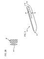
- FIG. 1 is a perspective view of a scalpel handle incorporating features of the invention
- FIG. 2A is a front view of the handle of FIG. 1 ;
- FIG. 2B is a sectional view taken along the line IIB-IIB of FIG. 1 ;
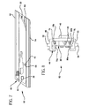
- FIG. 3 is a perspective view of a blade incorporating features of the invention.
- FIG. 4 is a side view (closed side) of a guard incorporating features of the invention.
- FIG. 5 is a side view (open side) of the guard of FIG. 4 ;
- FIG. 6 is a top view of the guard of FIG. 5 ;
- FIG. 7 is a side view of the guard of FIG. 5 with the blade positioned in the guard;
- FIG. 8 is a front view of the blade and guard assembly of FIG. 7 ;
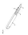
- FIG. 9 is a perspective view of the handle attached to the blade and guard assembly of FIG. 7 with the guard partially retracted into the handle;
- FIG. 10 is a front view of the surgical scalpel assembly of FIG. 9 ;
- FIG. 11 is a plan view of an alternative guard .
- FIG. 12 is a side view of another blade and guard assembly .
- a scalpel handle 10 of the invention is shown in Figs. 1, 2A , and 2B .
- the handle 10 can be made of any desired material, such as but not limited to plastics, metal, etc., and can be of any desired dimensions.
- the handle 10 has a substantially "C" shaped profile in cross section (i.e., has a substantially closed side and a substantially open side).
- the handle 10 has a first side wall 12, a top wall 14, and a bottom wall 16 that define an interior hollow space or cavity 18 within the handle 10.
- the handle 10 can be made of a single piece of material, such as metal, with the side wall 12, top wall 14, and bottom wall 16 being of a unitary structure.
- the handle 10 can have a second side wall opposite the first side wall 12 or, as shown in the exemplary embodiment, the second side of the handle 10 (opposite the first side wall 12) can be open.
- the handle 10 further includes a blade carrier 20 configured to engage a surgical blade as described in more detail below.
- the blade carrier 20 is formed as a conventional projection or "finger" extending from the front of the handle 10.
- the finger includes an attachment element 22 configured to engage a portion of the blade to hold the blade onto the handle 10 in conventional manner.
- the attachment element 22 is configured as a raised portion extending from the side of the finger.
- any conventional attachment means could be used.
- the handle 10 further includes an unlocking element 24.
- the unlocking element 24 is formed by a projection extending outwardly from the side of the finger to the rear of the attachment element 22.
- the handle 10 also includes at least one guide member to receive a blade guard as described in more detail below.
- the guide member(s) can be of any conventional design. However, in the illustrated exemplary embodiment, the guide members are configured as opposed grooves 26, 28 formed in the top wall 14 and bottom wall 16, respectively, of the handle 10 and extend at least partly along the length of the interior of the top wall 14 and bottom wall 16.
- the handle 10 also includes a guard locking device to allow the guard to be locked in a retracted position, i.e., such that at least a portion of the blade is exposed.
- the locking device is configured as a rib 29 extending along the handle cavity 18.
- the rib 29 includes an end surface 31 configured to engage a locking element, e.g., a locking boss, on the guard as described in more detail below.
- any conventional device to retain the guard in a retracted position could be used.
- FIG. 3 A blade 30 incorporating features of the invention is shown in FIG. 3 .
- the blade 30 can be of any conventional length or dimensions as are well known in the surgical art.
- the blade 30 has a front 32 and a rear 34 and includes an attachment member 36 configured to engage the attachment element 22 of the blade carrier 20 to attach the blade 30 to the handle 10.
- the attachment member 36 is configured as a conventional slot having a wider portion and a narrower portion configured to releasably engage the attachment element 22 on the handle 10.
- Such a conventional blade slot is well known in the art and will not be described in detail.
- the blade 30 can further include a retaining element, such as a first or retaining hole 38 positioned near the rear 34 of the blade 30.
- a retaining element such as a first or retaining hole 38 positioned near the rear 34 of the blade 30.
- the retaining hole 38 can be of any shape, as will be described below it is particularly advantageous if the retaining hole 38 is of a non-arcuate shape.
- non-arcuate is meant that the retaining hole 38 does not have a round or curved shape, such as a circular shape, but rather has one or more straight sides, such as a quadrilateral shape, for example a square or rectangular shape.
- the blade 30 may not have a separate retaining hole 38 but, rather, the attachment member 36 can be configured to receive a retaining device, as described in more detail below.
- the blade 30 can further include a locking element, such as a second or locking hole 40 which can be positioned forward of the retaining hole 38.
- a locking element such as a second or locking hole 40 which can be positioned forward of the retaining hole 38.
- the locking hole 40 can be of any desired shape but in the illustrated embodiment the locking hole 40 has an arcuate shape, i.e., a round shape.
- the guard 44 can be substantially "C" shaped in cross section and can have a side wall 46, a top wall 48, and a bottom wall 50 ( FIG. 8 ).
- the guard 44 can be made of any desired material, such as metal, plastic, or a combination of metal and plastic. However, it is to be understood that the guard 44 is not limited to this configuration but could have a closed structure, i.e., a second side wall opposite the first side wall 46.
- the guard 44 includes at least one guide element configured to engage the at least one guide member in the handle 10 as described in more detail below.
- the guide element(s) are configured as ribs or rails 52, 54 extending outwardly from the top wall 48 and bottom wall 50, respectively, of the guard 44.
- this is simply one exemplary configuration for the guide elements and that the invention is not limited to these specific guide elements.
- the guard 44 can further comprise a first or retaining arm 58 which can be formed integrally with the side wall 46.
- the retaining arm 58 can be of any desired shape and includes a retaining boss 60 located at or near the inner end of the retaining arm 58. In the illustrated embodiment, the retaining boss 60 is substantially rectangular in shape.
- the retaining boss 60 is configured to engage the retaining hole 38 in the blade 30, as described below.
- the portion of the retaining arm 58 with the retaining boss 60 can be biased inwardly, i.e., toward the interior of the guard 44, in any conventional manner.
- the guard 44 can further include a second or locking arm 62 which can be formed integrally with the guard side wall 46.
- the locking arm 62 can be a movable, e.g., cantilevered, arm with one end biased inwardly and having a locking boss 64 configured to engage the locking hole 40 on the blade 30 and/or the locking device (e.g., rib 29) on the handle 10 as described below.
- the outer end of the locking arm 62 can include a raised contact portion or button 66 which can be pushed to pivot the locking arm 62 around a pivot point 68 to move the locking boss 64 outwardly, e.g., out of the locking hole 40, to unlock the blade, as described below.
- the guard 44 can further include a blade deflection device 70 ( Figs. 5 and 6 ).
- the blade deflection device 70 is formed by a section of the top wall 48 which, upon the application of pressure by a user, can be bent inwardly (in the direction of arrow A in FIG. 6 ) as described below.
- the outer surface of the blade deflection device 70 can include a contact portion 72 having ribs for easier gripping and movement of the deflection device 70.
- Figs. 7 and 8 show a blade 30 positioned within the guard 44 .
- the blade 30 can be guided in the guard 44 by upper and lower channels 74, 76.
- the channels 74, 76 can be defined by opposed sets of upper ribs 78a, 78b and lower ribs 80a, 80b .
- the blade can be positioned in the guard 44 such that the retaining boss 60 of the retaining arm 58 releasably engages the retaining hole 38 on the blade 30 and presses the blade 30 against one side of the guide ribs 78a, 80a to retain the blade 30 in the guard 44 .
- the non-arcuate shape of the retaining hole 38 and retaining boss 60 helps prevent accidental slipping or rotation of the blade 30 around the retaining boss 60 . Additionally, the locking boss 64 engages the locking hole 40 on the blade 30 . This provides an additional safety feature preventing accidental withdrawal of the blade 30 from the guard 44 .
- the individual blade 30 and guard 44 components can be supplied separately or the guard 44 and blade 30 can be supplied as a pre-assembled unit (blade and guard assembly 82 ) and can be packaged in a sterile container, such as a foil container, and stored until desired.
- the blade 30 need not have a separate retaining hole 38 but, rather, the retaining boss 60 can be configured to engage the attachment slot 36 of the blade 30 .
- the guard 44 can further include a blade retention device 84 ( Figs. 7 and 8 ) configured to prevent accidental disengagement of the blade 30 from the handle 10 when the guard 44 is in a retracted position, as described below.
- the blade retention device 84 is configured as a projection or thicker portion of the guard 44 formed near the front of the guard 44 .
- the attachment element 22 (projection) on the handle finger is guided into the attachment member 36 (slot) in the blade 30 and pushed forward in conventional manner. This is done by initially positioning the handle 10 at an angle with respect to the blade 30 .
- This attachment method is well known in the surgical field and will not be described in detail.
- the attachment element 22 (projection) slides into the slot 36 until the unlocking element 24 aligns with the retaining hole 38 on the blade 30 and pushes the retaining boss 60 out of the retaining hole 38 to snap the blade 30 onto the finger.
- the attachment element 22 of the handle 10 is engaged with the attachment member 36 of the blade 30 and the unlocking element 24 is engaged in the retaining hole 38 .
- the locking boss 64 engages the locking hole 40 .
- the guide elements (rails 52, 54 ) on the guard 44 slide into the guide channels 74, 76 on the handle 10 such that the guard 44 can slide from a first position in which the guard 44 covers the cutting edge of the blade 30 to a second position in which the guard 44 is retracted into the internal cavity 18 of the handle 10 to uncover at least a portion of the cutting edge of the blade 30 , as shown in Figs. 9 and 10 .
- the guard 44 cannot initially be retracted into the handle 10 because the locking boss 64 is engaged in the locking hole 40 of the blade 30 . This prevents accidental movement of the guard 44 into the handle 10 and accidental exposure of the blade 30 until the locking boss 64 is released.
- the operator can press on the button 66 of the locking arm 62 to pivot the locking boss 64 out of the locking hole 40 in the blade 30 .
- This allows the guard 44 to be slid into the interior of the handle 10 , exposing the blade 30 .
- the scalpel assembly can then be used as intended.
- the locking boss 64 slides along the outer surface of the locking rib 29 .
- the locking boss 64 drops behind or engages the end surface 31 on the locking rib 29 due to the inward bias of the locking arm 62 .
- the button 66 on the locking arm 62 can be pushed to rotate the locking boss 64 out of engagement with the end surface 31 to allow the guard 44 to be slid forwardly on the handle 10 to again cover the blade 30 .
- the guard 44 can be slid forwardly until the locking boss 64 re-engages the locking hole 40 to lock the guard 44 in its extended position. Between uses, the guard 44 can be slid forward, i.e., out of the handle 10 , to cover the cutting edge of the blade 30 .
- the blade retention device 84 on the front of the guard 44 abuts or contacts the rear 34 of the blade 30 when the guard 44 is in the retracted position. This prevents deflection of the rear 34 of the blade 30 and, hence, prevents accidental disengagement of the finger from the blade slot 36 when the guard 44 is retracted into the handle 10.
- the blade and guard assembly 82 can be disconnected as a unit from the handle 10 and discarded.
- the guard 44 can be slid outwardly until the locking boss 64 engages the locking hole 40 of the blade 30.
- the handle 10 can be tilted at an angle with respect to the blade 30 and the attachment element 22 disengaged from the blade slot 36 by pulling the handle 10 rearwardly, as is known in the art.
- the unlocking element 24 is pulled out of the retaining hole 30.
- the bias on the retaining arm 58 causes the retaining boss 60 to re-engage with the retaining hole 38 to hold the blade 30 in the guard 44.
- the blade deflection device 70 can be used.
- the deflection device 70 can be pressed inwardly (in the direction of arrow A) to push against and deflect the rear 34 of the blade 30 toward the guard side wall 46 and, thus, bend or angle the rear 34 of the blade 30 toward the side wall 46.
- the deflection device 70 can be pressed inwardly (in the direction of arrow A) to push against and deflect the rear 34 of the blade 30 toward the guard side wall 46 and, thus, bend or angle the rear 34 of the blade 30 toward the side wall 46.
- the deflection device 70 could also be used to aid in attaching the handle 10 to the blade 30 by bending the rear 34 of the blade 30 to provide for easier insertion of the attachment element 22 of the handle 10 into the slot 36 of the blade 30 .
- FIG. 11 An alternative blade and guard assembly 88 not belonging to the invention is shown in FIG. 11 .
- the guard 89 includes opposed positioning ribs 90, 92 to align the forward portion of the blade 30.
- the guard 89 also includes a blade holding device, such as a hook or projection 94, that biases or bends the rear of the blade 30 when the blade 30 is in the guard 89.
- a blade holding device such as a hook or projection 94
- the handle 10 pushes the blade 30 forward and disengages the rear 34 of the blade 30 from the projection 94 to snap the rear 34 of the blade 30 onto the finger of the handle 10.
- FIG. 12 A still further blade and guard assembly 96 is shown in FIG. 12 .
- the blade 98 includes a rear engagement slot 100 defined between two rear arms 102, 104.
- Each arm 102, 104 includes an engagement member, such as a slot 106, 108, and an attachment member, such as a tooth or projection 110, 112.
- the guard 114 includes engagement elements, such as hooks 116, 118, to bias the arms 102, 104 outwardly when the blade 98 is positioned in the guard 114.
- the handle 120 includes a finger 122 having attachment elements, such as slots or depressions 124, 126.
- the finger 122 enters the slot 100 and pushes the blade 98 forward to disengage the hooks 116, 118 from the slots 106, 108 to cause the arms 102, 104 to snap toward each other and engage the projections 110, 112 on the blade 98 with the depressions 124, 126 on the handle 120 to lock the blade 98 onto the handle 120.
Landscapes
- Health & Medical Sciences (AREA)
- Life Sciences & Earth Sciences (AREA)
- Surgery (AREA)
- Heart & Thoracic Surgery (AREA)
- Engineering & Computer Science (AREA)
- Biomedical Technology (AREA)
- Nuclear Medicine, Radiotherapy & Molecular Imaging (AREA)
- Medical Informatics (AREA)
- Molecular Biology (AREA)
- Animal Behavior & Ethology (AREA)
- General Health & Medical Sciences (AREA)
- Public Health (AREA)
- Veterinary Medicine (AREA)
- Surgical Instruments (AREA)
Claims (5)
- Chirurgische Skalpellanordnung mit:(a) einem Griff (10) mit einem Klingenbefestigungselement (22);(b) einer Klinge (30) mit:einem Befestigungsteil (36), das zum Angreifen an dem Befestigungselement (22) des Griffs ausgebildet ist; undeinem Verriegelungselement (40); und(c) einem Schutz (44), der zwischen einer distalen ersten Position und einer in Bezug auf die Klinge (30) zurückgezogenen zweiten Position bewegbar ist,dadurch gekennzeichnet, dass
der Griff (10) ferne eine Verriegelungsvorrichtung (29) aufweist, und dass der Schutz (44) einen Verriegelungsarm (62) aufweist, der derart ausgebildet ist, dass er an einem Verriegelungselement (40) der Klinge (30) angreift, wenn sich der Schutz in der ersten Position befindet, und der derart ausgebildet ist, dass er an der Verriegelungsvorrichtung (29) des Griffs (10) angreift, wenn sich der Schutz in der zweiten Position befindet. - Skalpellanordnung nach Anspruch 1, bei welcher die Klinge (30) einen Schlitz (36), der zum Angreifen an dem Befestigungselement (22) eines Klingenträgers (20) des Griffs (10) ausgebildet ist, und ein Rückhalteloch (38) aufweist, das eine nicht gebogene Form hat und zum Angreifen an einem Rückhaltevorsprung (60) des Schutzes (44) ausgebildet ist.
- Skalpellanordnung nach Anspruch 1 oder 2, bei welcher der Griff (10) einander gegenüberliegende Führungskanäle (26, 28) aufweist und der Schutz (44) Schienen (52, 54) aufweist, die ausgebildet sind, um derart in die Schutzkanäle einzugreifen, dass der Schutz gleitend in den und aus dem Griff verschiebbar ist.
- Skalpellanordnung nach einem der Ansprüche 1-3, bei welcher der Schutz (44) einen bewegbaren Arm (58) mit einem Vorsprung (60) aufweist und die Klinge (30) ein Loch aufweist, das derart ausgebildet ist, dass es den Vorsprung (60) aufnimmt, wenn sich die Klinge in dem Schutz (44) befindet.
- Skalpellanordnung nach einem der Ansprüche 1-4, bei welcher der Schutz (44) eine Klingenauslenkvorrichtung (72) aufweist, die derart ausgebildet ist, dass sie einen hinteren Teil der Klinge (30) biegt, wenn sich die Klinge im Schutz (44) befindet.
Priority Applications (2)
| Application Number | Priority Date | Filing Date | Title |
|---|---|---|---|
| EP10161479A EP2215983A1 (de) | 2004-03-22 | 2005-03-17 | Chirurgische Skalpellanordnung |
| EP10161470A EP2215982A1 (de) | 2004-03-22 | 2005-03-17 | Chirurgische Skalpellanordnung |
Applications Claiming Priority (2)
| Application Number | Priority Date | Filing Date | Title |
|---|---|---|---|
| US805775 | 1991-12-12 | ||
| US10/805,775 US7172611B2 (en) | 2004-03-22 | 2004-03-22 | Surgical scalpel assembly |
Publications (3)
| Publication Number | Publication Date |
|---|---|
| EP1579815A2 EP1579815A2 (de) | 2005-09-28 |
| EP1579815A3 EP1579815A3 (de) | 2005-12-07 |
| EP1579815B1 true EP1579815B1 (de) | 2010-05-05 |
Family
ID=34862021
Family Applications (3)
| Application Number | Title | Priority Date | Filing Date |
|---|---|---|---|
| EP10161470A Withdrawn EP2215982A1 (de) | 2004-03-22 | 2005-03-17 | Chirurgische Skalpellanordnung |
| EP10161479A Withdrawn EP2215983A1 (de) | 2004-03-22 | 2005-03-17 | Chirurgische Skalpellanordnung |
| EP05005843A Expired - Lifetime EP1579815B1 (de) | 2004-03-22 | 2005-03-17 | Chirurgische Skalpellanordnung |
Family Applications Before (2)
| Application Number | Title | Priority Date | Filing Date |
|---|---|---|---|
| EP10161470A Withdrawn EP2215982A1 (de) | 2004-03-22 | 2005-03-17 | Chirurgische Skalpellanordnung |
| EP10161479A Withdrawn EP2215983A1 (de) | 2004-03-22 | 2005-03-17 | Chirurgische Skalpellanordnung |
Country Status (7)
| Country | Link |
|---|---|
| US (1) | US7172611B2 (de) |
| EP (3) | EP2215982A1 (de) |
| JP (1) | JP2005279267A (de) |
| AU (2) | AU2005201133B2 (de) |
| BR (1) | BRPI0501000A (de) |
| DE (1) | DE602005021007D1 (de) |
| ES (1) | ES2345202T3 (de) |
Families Citing this family (67)
| Publication number | Priority date | Publication date | Assignee | Title |
|---|---|---|---|---|
| US7632274B2 (en) * | 2000-02-16 | 2009-12-15 | Trans1 Inc. | Thin cutter blades with retaining film for preparing intervertebral disc spaces |
| US20070260270A1 (en) * | 2000-02-16 | 2007-11-08 | Trans1 Inc. | Cutter for preparing intervertebral disc space |
| CA2543295A1 (en) | 2003-10-23 | 2005-05-06 | Trans1 Inc. | Tools and tool kits for performing minimally invasive procedures on the spine |
| TWI369970B (en) | 2004-10-20 | 2012-08-11 | Beaver Visitec Int Us Inc | Surgical knife safety handle having user operable lock |
| CA2584865C (en) * | 2004-10-29 | 2013-06-25 | Medipurpose Pte. Ltd. | Safety scalpel |
| US8015712B2 (en) | 2004-10-29 | 2011-09-13 | Medipurpose Pte Ltd | Safety scalpel |
| US20060241664A1 (en) * | 2005-04-25 | 2006-10-26 | Globe Medical Tech, Inc. | Automatic retractable blade scalpel |
| US8114103B2 (en) * | 2005-09-14 | 2012-02-14 | James Edwin Rasco | Scalpel blade protector |
| US20080033466A1 (en) * | 2006-02-28 | 2008-02-07 | Trans1 Inc. | Surgical cutter with exchangeable cutter blades |
| JP2009528136A (ja) * | 2006-02-28 | 2009-08-06 | トランス1 インコーポレイテッド | 椎間板腔形成のための専用カッター刃 |
| CA2644196A1 (en) * | 2006-02-28 | 2007-09-07 | Trans1 Inc. | Cutter for preparing intervertebral disc space |
| US20080065113A1 (en) * | 2006-09-11 | 2008-03-13 | Smith Dean W | Suture cutter and remover |
| WO2008109066A1 (en) * | 2007-03-05 | 2008-09-12 | Alb Associates, Llc | Guarded surgical scalpel with means for mounting a blade thereon |
| US20090313836A1 (en) * | 2008-06-19 | 2009-12-24 | Wei Shao-Tsung | Safety cutter knife |
| US8205340B2 (en) * | 2008-07-26 | 2012-06-26 | Georgene Austria | Safety scalpel with blade retention |
| USD624185S1 (en) * | 2008-10-22 | 2010-09-21 | Swann- Morton Limited | Scalpel blade |
| US20100125289A1 (en) * | 2008-11-18 | 2010-05-20 | Aditya Dispomed Products Private Ltd. | Scalpel blade having dual indentations on back edge |
| SG166694A1 (en) * | 2009-05-15 | 2010-12-29 | Teng Jun Piao | A friendly surgical scalpel |
| US8696672B2 (en) * | 2010-01-22 | 2014-04-15 | Baxano Surgical, Inc. | Abrading tool for preparing intervertebral disc spaces |
| US8875405B2 (en) | 2010-04-09 | 2014-11-04 | Oasis Medical, Inc. | Micro surgical knife with safety feature |
| USD639432S1 (en) | 2010-08-31 | 2011-06-07 | Oasis Medical, Inc. | Handle for use with a micro surgical knife |
| MX2012014155A (es) * | 2010-06-28 | 2013-02-27 | Medipurpose Pte Ltd | Bisturi de seguridad. |
| US20120270195A1 (en) * | 2011-04-21 | 2012-10-25 | Velarde David M | Scalpel Brush |
| EP2757985B1 (de) * | 2011-09-23 | 2018-01-31 | Medi-Safe Surgicals (Pty) Ltd | Sicherheitszubehör für skalpellklinge |
| USD682418S1 (en) * | 2012-02-15 | 2013-05-14 | 3M Innovative Properties Company | Respirator belt having attachment slot |
| US9622773B2 (en) | 2012-03-19 | 2017-04-18 | Aspen Surgical Products, Inc. | Side activated safety scalpel for left and right hand users with blade removal system |
| CN102835992B (zh) * | 2012-09-05 | 2014-09-17 | 苏州施莱医疗器械有限公司 | 一次性手术刀刀片组件及配套使用的非一次性刀柄 |
| CN103786170B (zh) | 2012-10-26 | 2016-02-10 | 奥多艾格刀具公司 | 具有可替换刀片的刀具 |
| US10493641B2 (en) | 2012-10-26 | 2019-12-03 | Outdoor Edge Cutlery Corporation | Folding knife with replaceable blade |
| USD751882S1 (en) * | 2012-12-26 | 2016-03-22 | Outdoor Edge Cutlery Corporation | Replaceable blade |
| WO2014159225A2 (en) | 2013-03-14 | 2014-10-02 | Baxano Surgical, Inc. | Spinal implants and implantation system |
| USD1107856S1 (en) | 2023-07-14 | 2025-12-30 | Outdoor Edge Cutlery, Llc | Knife handle |
| USD1046591S1 (en) | 2023-07-14 | 2024-10-15 | Outdoor Edge Cutlery, Llc | Blade holder |
| USD1047654S1 (en) | 2023-07-14 | 2024-10-22 | Outdoor Edge Cutlery, Llc | Blade holder |
| USD1047656S1 (en) | 2023-07-14 | 2024-10-22 | Outdoor Edge Cutlery, Llc | Knife handle |
| USD1046589S1 (en) | 2023-07-14 | 2024-10-15 | Outdoor Edge Cutlery, Llc | Knife handle |
| USD869254S1 (en) | 2013-10-25 | 2019-12-10 | Outdoor Edge Cutlery Corporation | Blade |
| USD1133734S1 (en) | 2023-07-14 | 2026-07-14 | Outdoor Edge Cutlery, Llc | Knife handle |
| USD1009587S1 (en) | 2022-03-11 | 2024-01-02 | Outdoor Edge Cutlery, Llc | Caping blade |
| USD1135584S1 (en) | 2013-10-25 | 2026-07-21 | Outdoor Edge Cutlery, Llc | Removable knife blade |
| USD1047657S1 (en) | 2023-07-14 | 2024-10-22 | Outdoor Edge Cutlery, Llc | Knife handle |
| DE102014110745B4 (de) * | 2014-07-29 | 2016-02-11 | Mozart Ag | Messer und Klinge |
| US20160095614A1 (en) | 2014-10-03 | 2016-04-07 | Aspen Surgical Products, Inc. | Sharps blade applicator and storage device |
| USD747637S1 (en) | 2014-10-31 | 2016-01-19 | Outdoor Edge Cutlery Corporation | Double blade knife |
| USD764888S1 (en) | 2015-01-20 | 2016-08-30 | Outdoor Edge Cutlery Corporation | Knife |
| US10123815B2 (en) | 2015-02-13 | 2018-11-13 | Precision Engineered Products, Llc | Surgical knife |
| US10092314B2 (en) * | 2015-02-27 | 2018-10-09 | Medipurpose Pte Ltd | Safety scalpel with replaceable blade cartridge |
| CN104622542B (zh) * | 2015-03-03 | 2017-02-15 | 王彦军 | 一种微手术模组 |
| USD848812S1 (en) | 2016-01-15 | 2019-05-21 | Outdoor Edge Cutlery Corporation | Folding knife |
| USD813390S1 (en) | 2016-01-15 | 2018-03-20 | Aspen Surgical Products, Inc. | Surgical scalpel blade attachment |
| US20170265882A1 (en) | 2016-03-21 | 2017-09-21 | Aspen Surgical Products, Inc. | Safety scalpel handle |
| USD806498S1 (en) | 2016-05-27 | 2018-01-02 | Outdoor Edge Cutlery Corporation | Knife |
| CN106236201B (zh) | 2016-09-13 | 2018-09-14 | 苏州施莱医疗器械有限公司 | 护套型一次性安全手术刀 |
| US10610257B2 (en) | 2018-02-17 | 2020-04-07 | Nano 2.0 Business Press, Llc | Structural element with bayonet having a universal blade fitting with electrical source pod and terminal configuration |
| WO2019199940A1 (en) | 2018-04-11 | 2019-10-17 | University Of Virginia Patent Foundation | Surgical incision apparatus and related methods thereof |
| USD909170S1 (en) | 2019-01-08 | 2021-02-02 | Outdoor Edge Cutlery Corporation | Knife |
| USD904841S1 (en) * | 2019-03-27 | 2020-12-15 | Slice, Inc. | Corner stripping blade |
| US20220083097A1 (en) * | 2019-04-29 | 2022-03-17 | Hewlett-Packard Development Company, L.P. | Device accessories with attachment slots |
| USD918683S1 (en) | 2019-10-31 | 2021-05-11 | Outdoor Edge Cutlery Corporation | Replaceable blade |
| USD926551S1 (en) | 2020-01-21 | 2021-08-03 | Outdoor Edge Cutlery Corporation | Knife |
| USD989580S1 (en) | 2021-04-16 | 2023-06-20 | Outdoor Edge Cutlery, Llc | Replaceable blade |
| USD978680S1 (en) | 2021-06-04 | 2023-02-21 | K2M, Inc. | Blade sleeve |
| USD1030430S1 (en) * | 2022-03-22 | 2024-06-11 | United States Government As Represented By The Department Of Veterans Affairs | Knife blade |
| USD1134854S1 (en) * | 2023-10-19 | 2026-07-14 | Nano Surgical Inc. | Surgical instrument bit |
| USD1110820S1 (en) * | 2023-10-31 | 2026-02-03 | Aob Products Company | Knife blade |
| USD1133809S1 (en) | 2024-07-03 | 2026-07-14 | Outdoor Edge Cutlery, Llc | Knife blade |
| USD1086841S1 (en) | 2024-07-22 | 2025-08-05 | Outdoor Edge Cutlery, Llc | Knife blade |
Family Cites Families (72)
| Publication number | Priority date | Publication date | Assignee | Title |
|---|---|---|---|---|
| US2735176A (en) | 1956-02-21 | Veterinary surgical knife | ||
| US1195169A (en) | 1916-08-22 | Masvin e | ||
| US469783A (en) | 1892-03-01 | Punch | ||
| US1469783A (en) * | 1922-01-17 | 1923-10-09 | Harry M Essington | Storage-battery lamp and means for operating same |
| US1914153A (en) | 1931-09-08 | 1933-06-13 | John J Ogden | Surgical knife |
| US2304332A (en) | 1939-11-10 | 1942-12-08 | Conrad Razor Blade Co Inc | Scraping device |
| US2280463A (en) * | 1941-01-15 | 1942-04-21 | Eugene D Williamson | Combination tool |
| CH243732A (de) * | 1945-08-11 | 1946-07-31 | Peyer Ernst | Messer mit Handgriff und auswechselbarer Klinge. |
| US2611178A (en) | 1947-03-03 | 1952-09-23 | Burdette E Bostwick | Pocket implement |
| US2885780A (en) | 1957-12-03 | 1959-05-12 | Floyd A Campbell | Marking tool |
| US3025598A (en) | 1958-10-13 | 1962-03-20 | Gillette Co | Knife |
| US2960769A (en) | 1959-07-10 | 1960-11-22 | John J Matwijcow | Scalpel handle |
| US3412467A (en) | 1966-11-25 | 1968-11-26 | John J. Matwijcow | Surgical scalpel |
| US3657812A (en) | 1970-09-28 | 1972-04-25 | G & L Ind Inc | Retractible tool holder |
| US3706106A (en) | 1971-01-18 | 1972-12-19 | Norbert Leopoldi | Surgical knife |
| US3889368A (en) | 1973-07-06 | 1975-06-17 | Conde Kk | Knife for cutting in sliding contact with ruler edge |
| US3943627A (en) | 1973-11-28 | 1976-03-16 | Stanley Jr Conrad | Front loading utility knife |
| US3906626A (en) | 1974-04-19 | 1975-09-23 | Becton Dickinson Co | Disposable surgical scalpel |
| US3905101A (en) | 1974-04-19 | 1975-09-16 | Becton Dickinson Co | Disposable surgical scalpel |
| US4091537A (en) | 1977-04-26 | 1978-05-30 | Stevenson Machine Shop | Safety utility knife |
| US4393587A (en) | 1981-04-23 | 1983-07-19 | Kloosterman William A | Spring shielded safety knife |
| US4414974A (en) | 1981-06-09 | 1983-11-15 | General Conveyors Limited | Microsurgical knife |
| US4516575A (en) | 1982-06-03 | 1985-05-14 | Coopervision, Inc. | Surgical scalpel |
| US4491132A (en) | 1982-08-06 | 1985-01-01 | Zimmer, Inc. | Sheath and retractable surgical tool combination |
| US4499898A (en) | 1982-08-23 | 1985-02-19 | Koi Associates | Surgical knife with controllably extendable blade and gauge therefor |
| US4538356A (en) | 1982-08-23 | 1985-09-03 | Koi Associates, Inc. | Surgical knife with controllably extendable blade and gauge therefor |
| US4576164A (en) | 1983-11-14 | 1986-03-18 | Richeson W George | Knife with locking shroud |
| US4523379A (en) | 1984-05-02 | 1985-06-18 | Tekna | Knife with retractable sheath |
| US4757612A (en) | 1985-03-21 | 1988-07-19 | Preposreve S.A.R.L. | Fixed-blade knife with retractable blade cover |
| IL75096A (en) | 1985-05-05 | 1989-05-15 | Porat Michael | Scalpel |
| US4630378A (en) | 1985-06-13 | 1986-12-23 | Pilling Co. | Gauge for extensible-blade surgical knife |
| US4662075A (en) | 1985-08-22 | 1987-05-05 | Magnum Diamond Reclamation, Inc. | Apparatus and method for setting knife blade depth |
| US4660287A (en) | 1985-11-01 | 1987-04-28 | Decker John R | Knife with replaceable blade |
| GB8530210D0 (en) | 1985-12-07 | 1986-01-15 | Duckworth & Kent Surgical Inst | Surgical knives |
| GB2187989B (en) | 1986-03-18 | 1989-11-15 | Sabre Int Prod Ltd | Knives |
| US4815218A (en) | 1986-06-13 | 1989-03-28 | Cilco, Inc. | Gauge for calibrating surgical scalpel |
| DE3622342A1 (de) | 1986-07-03 | 1988-01-14 | Beermann Kg Martor Argentax | Messer |
| GB2192358B (en) | 1986-07-08 | 1989-12-20 | Shirley Inst The | Knife |
| US4735202A (en) | 1986-10-06 | 1988-04-05 | Alcon Laboratories, Inc. | Microsurgical knife with locking blade guard |
| DE3722899A1 (de) | 1987-07-08 | 1989-01-19 | Peters Tim | Skalpell |
| US4803751A (en) | 1987-07-16 | 1989-02-14 | Morison Cousins | Scraper |
| US4823457A (en) | 1988-04-20 | 1989-04-25 | American Safety Razor Company | Disposable surgical scalpel |
| US5139507A (en) | 1989-04-06 | 1992-08-18 | Stuart Dolgin | Surgical scalpel with retractable blade guard |
| US5071426A (en) | 1989-04-06 | 1991-12-10 | Stuart Dolgin | Surgical scalpel with retractable blade guard |
| US4985034A (en) | 1989-06-01 | 1991-01-15 | Board Of Regents, The University Of Texas System | Safety surgical blade, handle and shield |
| US5116351A (en) * | 1989-10-11 | 1992-05-26 | Frassetti Paris R | Safety scalpel |
| US5035703A (en) | 1990-05-09 | 1991-07-30 | Baskas Morris J | Disposable syringe needle and scalpel holder |
| US5015252A (en) | 1990-08-13 | 1991-05-14 | Jones Mark W | Surgical forceps with suture cutters |
| US5258001A (en) | 1991-09-05 | 1993-11-02 | Baylor College Of Medicine | Retractable scalpel with blade-activated lock |
| US5299357A (en) | 1991-12-18 | 1994-04-05 | American Safety Razor Company | Disposable surgical scalpel with safety guard |
| US5309641A (en) | 1991-12-18 | 1994-05-10 | American Safety Razor Company | Disposable surgical scalpel with safety guard |
| US5496340A (en) * | 1992-01-24 | 1996-03-05 | Leonard Bloom | Combination guarded surgical scalpel and blade stripper |
| US5411512A (en) | 1992-01-24 | 1995-05-02 | Leonard Bloom | Guarded surgical scalpel |
| US5250063A (en) | 1992-01-24 | 1993-10-05 | Leonard Bloom | Surgical scalpel with retractable guard |
| US5207696A (en) | 1992-04-30 | 1993-05-04 | Medical Sterile Products, Inc. | Surgical scalpel |
| US5201748A (en) | 1992-06-01 | 1993-04-13 | Newman Philip H | Retractable-bladed surgical scalpel |
| US5250064A (en) | 1992-10-07 | 1993-10-05 | Biological Tissue Reserve, Inc. | Shield for surgical scalpel blades |
| US5292329A (en) | 1992-12-04 | 1994-03-08 | Werner Richard S | Retractable surgical knife |
| US5344424A (en) | 1993-03-12 | 1994-09-06 | Roberts Philip L | Selectively retractable, disposable surgical knife |
| US5342379A (en) | 1993-06-01 | 1994-08-30 | Volinsky Fredric G | Safety scalpel |
| US5938675A (en) | 1993-12-08 | 1999-08-17 | Beckton, Dickinson And Company | Surgical scalpel |
| AU1301795A (en) | 1993-12-08 | 1995-06-27 | Devon Industries, Inc. | Surgical scalpel |
| US6053929A (en) | 1993-12-08 | 2000-04-25 | Becton Dickinson And Company | Surgical scalpel |
| US5938676A (en) | 1993-12-08 | 1999-08-17 | Becton, Dickinson & Company | Surgical scalpel |
| US5919201A (en) | 1993-12-08 | 1999-07-06 | Becton, Dickinson And Company | Surgical scalpel |
| US5556409A (en) * | 1995-08-04 | 1996-09-17 | Haining; Michael L. | Disposable scalpel |
| US5676677A (en) * | 1996-03-21 | 1997-10-14 | Landis; Robert M. | Guard for the blade of a knife |
| US5868771A (en) * | 1997-07-25 | 1999-02-09 | Pabban Development, Inc. | Scalpel blade cover |
| US6216868B1 (en) * | 1999-07-09 | 2001-04-17 | Stonybrook Surgical Innovations Inc. | Surgical blade system |
| AU712212B3 (en) * | 1999-07-15 | 1999-10-28 | Occupational & Medical Innovations Ltd | A surgical scalpel with retractable guard |
| US6574868B1 (en) * | 2000-03-01 | 2003-06-10 | Steven D Overholt | Knife with replaceable cutting element |
| US6626925B2 (en) | 2001-03-29 | 2003-09-30 | Becton Dickinson And Company | Shielded surgical scalpel |
-
2004
- 2004-03-22 US US10/805,775 patent/US7172611B2/en not_active Expired - Fee Related
-
2005
- 2005-03-16 AU AU2005201133A patent/AU2005201133B2/en not_active Ceased
- 2005-03-17 DE DE602005021007T patent/DE602005021007D1/de not_active Expired - Lifetime
- 2005-03-17 EP EP10161470A patent/EP2215982A1/de not_active Withdrawn
- 2005-03-17 EP EP10161479A patent/EP2215983A1/de not_active Withdrawn
- 2005-03-17 EP EP05005843A patent/EP1579815B1/de not_active Expired - Lifetime
- 2005-03-17 ES ES05005843T patent/ES2345202T3/es not_active Expired - Lifetime
- 2005-03-21 BR BR0501000-4A patent/BRPI0501000A/pt not_active IP Right Cessation
- 2005-03-22 JP JP2005081806A patent/JP2005279267A/ja active Pending
-
2010
- 2010-06-16 AU AU2010202506A patent/AU2010202506B2/en not_active Ceased
Also Published As
| Publication number | Publication date |
|---|---|
| ES2345202T3 (es) | 2010-09-17 |
| EP2215982A1 (de) | 2010-08-11 |
| US20050228420A1 (en) | 2005-10-13 |
| US7172611B2 (en) | 2007-02-06 |
| AU2005201133A1 (en) | 2005-10-06 |
| JP2005279267A (ja) | 2005-10-13 |
| DE602005021007D1 (de) | 2010-06-17 |
| AU2005201133B2 (en) | 2010-03-25 |
| EP2215983A1 (de) | 2010-08-11 |
| AU2010202506A1 (en) | 2010-07-08 |
| BRPI0501000A (pt) | 2005-11-01 |
| AU2010202506B2 (en) | 2011-09-15 |
| EP1579815A3 (de) | 2005-12-07 |
| EP1579815A2 (de) | 2005-09-28 |
Similar Documents
| Publication | Publication Date | Title |
|---|---|---|
| US7172611B2 (en) | Surgical scalpel assembly | |
| EP1194073B1 (de) | Chirurgisches skalpell mit einziehbarem messerschutz | |
| US5868771A (en) | Scalpel blade cover | |
| EP2434967B1 (de) | Klingeneinheit für ein chirurgisches skalpell | |
| JP4596917B2 (ja) | 引込み可能ガード付き外科用メス | |
| US5919201A (en) | Surgical scalpel | |
| EP0988832B1 (de) | Chirurgisches Skalpell | |
| US5772638A (en) | Protector for needle | |
| US20090192538A1 (en) | Safety scalpel handle | |
| US5938675A (en) | Surgical scalpel | |
| EP2367483B1 (de) | Skalpell mit entfernbarer klingenanordnung | |
| JP4814893B2 (ja) | ブレード収納ケース | |
| US8596453B2 (en) | Scalpel blade remover and sharps container | |
| JP5373325B2 (ja) | 留置針 | |
| JP5335030B2 (ja) | ブレード収納ケース | |
| HK1195722A1 (zh) | 手术刀刀片安全配件 | |
| HK1195722B (en) | Scalpel blade safety accessory | |
| HK40009394A (en) | Safety scalpel with replaceable blade cartridge | |
| HK40009394B (en) | Safety scalpel with replaceable blade cartridge |
Legal Events
| Date | Code | Title | Description |
|---|---|---|---|
| PUAI | Public reference made under article 153(3) epc to a published international application that has entered the european phase |
Free format text: ORIGINAL CODE: 0009012 |
|
| AK | Designated contracting states |
Kind code of ref document: A2 Designated state(s): AT BE BG CH CY CZ DE DK EE ES FI FR GB GR HU IE IS IT LI LT LU MC NL PL PT RO SE SI SK TR |
|
| AX | Request for extension of the european patent |
Extension state: AL BA HR LV MK YU |
|
| PUAL | Search report despatched |
Free format text: ORIGINAL CODE: 0009013 |
|
| AK | Designated contracting states |
Kind code of ref document: A3 Designated state(s): AT BE BG CH CY CZ DE DK EE ES FI FR GB GR HU IE IS IT LI LT LU MC NL PL PT RO SE SI SK TR |
|
| AX | Request for extension of the european patent |
Extension state: AL BA HR LV MK YU |
|
| 17P | Request for examination filed |
Effective date: 20060412 |
|
| AKX | Designation fees paid |
Designated state(s): DE ES FR GB IT |
|
| 17Q | First examination report despatched |
Effective date: 20080310 |
|
| GRAP | Despatch of communication of intention to grant a patent |
Free format text: ORIGINAL CODE: EPIDOSNIGR1 |
|
| GRAS | Grant fee paid |
Free format text: ORIGINAL CODE: EPIDOSNIGR3 |
|
| GRAA | (expected) grant |
Free format text: ORIGINAL CODE: 0009210 |
|
| AK | Designated contracting states |
Kind code of ref document: B1 Designated state(s): DE ES FR GB IT |
|
| REG | Reference to a national code |
Ref country code: GB Ref legal event code: FG4D |
|
| REF | Corresponds to: |
Ref document number: 602005021007 Country of ref document: DE Date of ref document: 20100617 Kind code of ref document: P |
|
| REG | Reference to a national code |
Ref country code: ES Ref legal event code: FG2A Ref document number: 2345202 Country of ref document: ES Kind code of ref document: T3 |
|
| PLBE | No opposition filed within time limit |
Free format text: ORIGINAL CODE: 0009261 |
|
| STAA | Information on the status of an ep patent application or granted ep patent |
Free format text: STATUS: NO OPPOSITION FILED WITHIN TIME LIMIT |
|
| 26N | No opposition filed |
Effective date: 20110208 |
|
| REG | Reference to a national code |
Ref country code: DE Ref legal event code: R097 Ref document number: 602005021007 Country of ref document: DE Effective date: 20110207 |
|
| REG | Reference to a national code |
Ref country code: GB Ref legal event code: 732E Free format text: REGISTERED BETWEEN 20110512 AND 20110518 |
|
| REG | Reference to a national code |
Ref country code: DE Ref legal event code: R082 Ref document number: 602005021007 Country of ref document: DE Representative=s name: PATENTANWAELTE VON KREISLER, SELTING, WERNER, DE |
|
| REG | Reference to a national code |
Ref country code: DE Ref legal event code: R082 Ref document number: 602005021007 Country of ref document: DE Representative=s name: VON KREISLER SELTING WERNER - PARTNERSCHAFT VO, DE Effective date: 20110719 Ref country code: DE Ref legal event code: R081 Ref document number: 602005021007 Country of ref document: DE Owner name: ASPEN SURGICAL PRODUCTS, INC., CALEDONIA, US Free format text: FORMER OWNER: BECTON DICKINSON AND CO., FRANKLIN LAKES, N.J., US Effective date: 20110719 |
|
| REG | Reference to a national code |
Ref country code: ES Ref legal event code: PC2A Owner name: ASPEN SURGICAL PRODUCTS, INC. Effective date: 20120116 |
|
| PGFP | Annual fee paid to national office [announced via postgrant information from national office to epo] |
Ref country code: IT Payment date: 20120316 Year of fee payment: 8 |
|
| PGFP | Annual fee paid to national office [announced via postgrant information from national office to epo] |
Ref country code: ES Payment date: 20130325 Year of fee payment: 9 Ref country code: GB Payment date: 20130225 Year of fee payment: 9 Ref country code: FR Payment date: 20130315 Year of fee payment: 9 |
|
| PGFP | Annual fee paid to national office [announced via postgrant information from national office to epo] |
Ref country code: DE Payment date: 20130328 Year of fee payment: 9 |
|
| REG | Reference to a national code |
Ref country code: DE Ref legal event code: R119 Ref document number: 602005021007 Country of ref document: DE |
|
| GBPC | Gb: european patent ceased through non-payment of renewal fee |
Effective date: 20140317 |
|
| REG | Reference to a national code |
Ref country code: FR Ref legal event code: ST Effective date: 20141128 |
|
| REG | Reference to a national code |
Ref country code: DE Ref legal event code: R119 Ref document number: 602005021007 Country of ref document: DE Effective date: 20141001 |
|
| PG25 | Lapsed in a contracting state [announced via postgrant information from national office to epo] |
Ref country code: DE Free format text: LAPSE BECAUSE OF NON-PAYMENT OF DUE FEES Effective date: 20141001 Ref country code: FR Free format text: LAPSE BECAUSE OF NON-PAYMENT OF DUE FEES Effective date: 20140331 Ref country code: GB Free format text: LAPSE BECAUSE OF NON-PAYMENT OF DUE FEES Effective date: 20140317 |
|
| PG25 | Lapsed in a contracting state [announced via postgrant information from national office to epo] |
Ref country code: IT Free format text: LAPSE BECAUSE OF NON-PAYMENT OF DUE FEES Effective date: 20140317 |
|
| REG | Reference to a national code |
Ref country code: ES Ref legal event code: FD2A Effective date: 20150507 |
|
| PG25 | Lapsed in a contracting state [announced via postgrant information from national office to epo] |
Ref country code: ES Free format text: LAPSE BECAUSE OF NON-PAYMENT OF DUE FEES Effective date: 20140318 |