EP1578672B1 - Contenant - Google Patents
Contenant Download PDFInfo
- Publication number
- EP1578672B1 EP1578672B1 EP03775590A EP03775590A EP1578672B1 EP 1578672 B1 EP1578672 B1 EP 1578672B1 EP 03775590 A EP03775590 A EP 03775590A EP 03775590 A EP03775590 A EP 03775590A EP 1578672 B1 EP1578672 B1 EP 1578672B1
- Authority
- EP
- European Patent Office
- Prior art keywords
- blank
- lid
- wall panel
- panel
- end wall
- Prior art date
- Legal status (The legal status is an assumption and is not a legal conclusion. Google has not performed a legal analysis and makes no representation as to the accuracy of the status listed.)
- Expired - Lifetime
Links
- 239000000463 material Substances 0.000 claims abstract description 48
- 239000000853 adhesive Substances 0.000 claims description 28
- 230000002745 absorbent Effects 0.000 claims description 25
- 239000002250 absorbent Substances 0.000 claims description 25
- 230000001070 adhesive effect Effects 0.000 claims description 24
- 239000012530 fluid Substances 0.000 claims description 16
- XLYOFNOQVPJJNP-UHFFFAOYSA-N water Substances O XLYOFNOQVPJJNP-UHFFFAOYSA-N 0.000 claims description 6
- 230000000844 anti-bacterial effect Effects 0.000 claims description 5
- 239000003899 bactericide agent Substances 0.000 claims description 5
- 239000005871 repellent Substances 0.000 claims description 5
- 235000013305 food Nutrition 0.000 claims description 4
- 239000011248 coating agent Substances 0.000 claims description 3
- 238000000576 coating method Methods 0.000 claims description 3
- 238000000034 method Methods 0.000 claims description 3
- 238000004806 packaging method and process Methods 0.000 claims description 3
- 239000011888 foil Substances 0.000 claims description 2
- 230000005855 radiation Effects 0.000 claims description 2
- 241000251468 Actinopterygii Species 0.000 description 21
- 239000010410 layer Substances 0.000 description 16
- 239000004033 plastic Substances 0.000 description 6
- 229920003023 plastic Polymers 0.000 description 6
- 239000000123 paper Substances 0.000 description 5
- 238000003860 storage Methods 0.000 description 4
- 239000002023 wood Substances 0.000 description 3
- 241000894006 Bacteria Species 0.000 description 2
- 241000186781 Listeria Species 0.000 description 2
- 241000607142 Salmonella Species 0.000 description 2
- 239000012790 adhesive layer Substances 0.000 description 2
- 239000002390 adhesive tape Substances 0.000 description 2
- 239000008280 blood Substances 0.000 description 2
- 210000004369 blood Anatomy 0.000 description 2
- DQXBYHZEEUGOBF-UHFFFAOYSA-N but-3-enoic acid;ethene Chemical compound C=C.OC(=O)CC=C DQXBYHZEEUGOBF-UHFFFAOYSA-N 0.000 description 2
- 239000005038 ethylene vinyl acetate Substances 0.000 description 2
- 238000009413 insulation Methods 0.000 description 2
- 239000011344 liquid material Substances 0.000 description 2
- 238000012856 packing Methods 0.000 description 2
- 229920001200 poly(ethylene-vinyl acetate) Polymers 0.000 description 2
- 239000000126 substance Substances 0.000 description 2
- 241000208199 Buxus sempervirens Species 0.000 description 1
- 230000004888 barrier function Effects 0.000 description 1
- 238000010276 construction Methods 0.000 description 1
- 230000002708 enhancing effect Effects 0.000 description 1
- 239000003292 glue Substances 0.000 description 1
- 238000005470 impregnation Methods 0.000 description 1
- 238000003475 lamination Methods 0.000 description 1
- 239000007788 liquid Substances 0.000 description 1
- 238000004519 manufacturing process Methods 0.000 description 1
- 229920005606 polypropylene copolymer Polymers 0.000 description 1
- 239000011241 protective layer Substances 0.000 description 1
- 230000009182 swimming Effects 0.000 description 1
Images


Classifications
-
- B—PERFORMING OPERATIONS; TRANSPORTING
- B65—CONVEYING; PACKING; STORING; HANDLING THIN OR FILAMENTARY MATERIAL
- B65D—CONTAINERS FOR STORAGE OR TRANSPORT OF ARTICLES OR MATERIALS, e.g. BAGS, BARRELS, BOTTLES, BOXES, CANS, CARTONS, CRATES, DRUMS, JARS, TANKS, HOPPERS, FORWARDING CONTAINERS; ACCESSORIES, CLOSURES, OR FITTINGS THEREFOR; PACKAGING ELEMENTS; PACKAGES
- B65D5/00—Rigid or semi-rigid containers of polygonal cross-section, e.g. boxes, cartons or trays, formed by folding or erecting one or more blanks made of paper
- B65D5/20—Rigid or semi-rigid containers of polygonal cross-section, e.g. boxes, cartons or trays, formed by folding or erecting one or more blanks made of paper by folding-up portions connected to a central panel from all sides to form a container body, e.g. of tray-like form
- B65D5/24—Rigid or semi-rigid containers of polygonal cross-section, e.g. boxes, cartons or trays, formed by folding or erecting one or more blanks made of paper by folding-up portions connected to a central panel from all sides to form a container body, e.g. of tray-like form with adjacent sides interconnected by gusset folds
- B65D5/248—Rigid or semi-rigid containers of polygonal cross-section, e.g. boxes, cartons or trays, formed by folding or erecting one or more blanks made of paper by folding-up portions connected to a central panel from all sides to form a container body, e.g. of tray-like form with adjacent sides interconnected by gusset folds and at least one side being extended and doubled-over to enclose the adjacent gusset flaps
-
- B—PERFORMING OPERATIONS; TRANSPORTING
- B65—CONVEYING; PACKING; STORING; HANDLING THIN OR FILAMENTARY MATERIAL
- B65D—CONTAINERS FOR STORAGE OR TRANSPORT OF ARTICLES OR MATERIALS, e.g. BAGS, BARRELS, BOTTLES, BOXES, CANS, CARTONS, CRATES, DRUMS, JARS, TANKS, HOPPERS, FORWARDING CONTAINERS; ACCESSORIES, CLOSURES, OR FITTINGS THEREFOR; PACKAGING ELEMENTS; PACKAGES
- B65D5/00—Rigid or semi-rigid containers of polygonal cross-section, e.g. boxes, cartons or trays, formed by folding or erecting one or more blanks made of paper
- B65D5/42—Details of containers or of foldable or erectable container blanks
- B65D5/64—Lids
- B65D5/68—Telescope flanged lids
-
- B—PERFORMING OPERATIONS; TRANSPORTING
- B65—CONVEYING; PACKING; STORING; HANDLING THIN OR FILAMENTARY MATERIAL
- B65D—CONTAINERS FOR STORAGE OR TRANSPORT OF ARTICLES OR MATERIALS, e.g. BAGS, BARRELS, BOTTLES, BOXES, CANS, CARTONS, CRATES, DRUMS, JARS, TANKS, HOPPERS, FORWARDING CONTAINERS; ACCESSORIES, CLOSURES, OR FITTINGS THEREFOR; PACKAGING ELEMENTS; PACKAGES
- B65D81/00—Containers, packaging elements, or packages, for contents presenting particular transport or storage problems, or adapted to be used for non-packaging purposes after removal of contents
- B65D81/24—Adaptations for preventing deterioration or decay of contents; Applications to the container or packaging material of food preservatives, fungicides, pesticides or animal repellants
- B65D81/26—Adaptations for preventing deterioration or decay of contents; Applications to the container or packaging material of food preservatives, fungicides, pesticides or animal repellants with provision for draining away, or absorbing, or removing by ventilation, fluids, e.g. exuded by contents; Applications of corrosion inhibitors or desiccators
- B65D81/264—Adaptations for preventing deterioration or decay of contents; Applications to the container or packaging material of food preservatives, fungicides, pesticides or animal repellants with provision for draining away, or absorbing, or removing by ventilation, fluids, e.g. exuded by contents; Applications of corrosion inhibitors or desiccators for absorbing liquids
-
- B—PERFORMING OPERATIONS; TRANSPORTING
- B65—CONVEYING; PACKING; STORING; HANDLING THIN OR FILAMENTARY MATERIAL
- B65D—CONTAINERS FOR STORAGE OR TRANSPORT OF ARTICLES OR MATERIALS, e.g. BAGS, BARRELS, BOTTLES, BOXES, CANS, CARTONS, CRATES, DRUMS, JARS, TANKS, HOPPERS, FORWARDING CONTAINERS; ACCESSORIES, CLOSURES, OR FITTINGS THEREFOR; PACKAGING ELEMENTS; PACKAGES
- B65D81/00—Containers, packaging elements, or packages, for contents presenting particular transport or storage problems, or adapted to be used for non-packaging purposes after removal of contents
- B65D81/24—Adaptations for preventing deterioration or decay of contents; Applications to the container or packaging material of food preservatives, fungicides, pesticides or animal repellants
- B65D81/26—Adaptations for preventing deterioration or decay of contents; Applications to the container or packaging material of food preservatives, fungicides, pesticides or animal repellants with provision for draining away, or absorbing, or removing by ventilation, fluids, e.g. exuded by contents; Applications of corrosion inhibitors or desiccators
- B65D81/261—Adaptations for preventing deterioration or decay of contents; Applications to the container or packaging material of food preservatives, fungicides, pesticides or animal repellants with provision for draining away, or absorbing, or removing by ventilation, fluids, e.g. exuded by contents; Applications of corrosion inhibitors or desiccators for draining or collecting liquids without absorbing them
-
- B—PERFORMING OPERATIONS; TRANSPORTING
- B65—CONVEYING; PACKING; STORING; HANDLING THIN OR FILAMENTARY MATERIAL
- B65D—CONTAINERS FOR STORAGE OR TRANSPORT OF ARTICLES OR MATERIALS, e.g. BAGS, BARRELS, BOTTLES, BOXES, CANS, CARTONS, CRATES, DRUMS, JARS, TANKS, HOPPERS, FORWARDING CONTAINERS; ACCESSORIES, CLOSURES, OR FITTINGS THEREFOR; PACKAGING ELEMENTS; PACKAGES
- B65D81/00—Containers, packaging elements, or packages, for contents presenting particular transport or storage problems, or adapted to be used for non-packaging purposes after removal of contents
- B65D81/24—Adaptations for preventing deterioration or decay of contents; Applications to the container or packaging material of food preservatives, fungicides, pesticides or animal repellants
- B65D81/28—Applications of food preservatives, fungicides, pesticides or animal repellants
-
- B—PERFORMING OPERATIONS; TRANSPORTING
- B65—CONVEYING; PACKING; STORING; HANDLING THIN OR FILAMENTARY MATERIAL
- B65D—CONTAINERS FOR STORAGE OR TRANSPORT OF ARTICLES OR MATERIALS, e.g. BAGS, BARRELS, BOTTLES, BOXES, CANS, CARTONS, CRATES, DRUMS, JARS, TANKS, HOPPERS, FORWARDING CONTAINERS; ACCESSORIES, CLOSURES, OR FITTINGS THEREFOR; PACKAGING ELEMENTS; PACKAGES
- B65D81/00—Containers, packaging elements, or packages, for contents presenting particular transport or storage problems, or adapted to be used for non-packaging purposes after removal of contents
- B65D81/38—Containers, packaging elements, or packages, for contents presenting particular transport or storage problems, or adapted to be used for non-packaging purposes after removal of contents with thermal insulation
- B65D81/3848—Containers, packaging elements, or packages, for contents presenting particular transport or storage problems, or adapted to be used for non-packaging purposes after removal of contents with thermal insulation semi-rigid container folded up from one or more blanks
Definitions
- This invention relates to a container comprising a base and lid, each made of stiff yet foldable sheet material, e.g. corrugated material.
- the container is particularly, but not exclusively, suitable for containing food produce such as, for example, fresh fish.
- the invention also relates to a blank of stiff yet foldable sheet material, e.g. corrugated material, which is erectable into a base of a container and to a packaging method.
- a blank made of stiff yet foldable sheet material according to claim 1.
- Background art EP-A-1 122 177 , NL-A-1 019 538 and GB-A-614 444 relate to a blank of stiff yet foldable sheet of material and an open-topped container erected from such a blank, comprising a rectangular bottom, double thickness side walls extending upwardly from said bottom, double thickness end walls extending upwardly from said bottom, and a gusset at each corner of the container.
- a blank according to the invention enables a container base to be erected having double thickness side and end walls thereby enhancing the thermally insulating properties of the container base.
- the second side wall panels are folded downwardly outside the first side wall panels in the erected container in which case the second end wall panels are also folded outside the first end wall panels.
- the second side wall panels it is also possible for the second side wall panels to be folded downwardly inside the first side wall panels and in this case the second end wall panels would be folded downwardly inside the corresponding first end wall panels.
- each end flap is shaped so as to overlap the other end flap of the pair when the blank is erected into as container base.
- the blank has adhesive means for connecting the second end wall panels to the underlying end flaps.
- the adhesive means comprises double-sided adhesive strip or tape one side of which is adhered to the blank and the other side of which has a removable non-adhesive covering thereon.
- the adhesive strip or tape is provided on the second end wall panels although, alternatively, it could be provided on the end flaps.
- the sheet material of the or each blank comprises corrugated material, e.g. corrugated fibreboard or cardboard.
- Corrugated material with its cavities, has good thermally insulating properties and these thermally insulating properties are considerably enhanced in an erected container having walls of more than a single thickness.
- the provision of good thermal insulation is important since any ice added to the contents in use, e.g. whilst fish is being packed on a trawler, will thaw less quickly the better the thermally insulating properties of the walls of the fish box.
- the sheet material will be provided on both, sides with a water resistant coating, such as a plastics material and/or wax, or a laminated finish or may be impregnated with water-repellent material.
- a water resistant coating such as a plastics material and/or wax, or a laminated finish or may be impregnated with water-repellent material.
- water-repellent corrugated sheet material is described in US-A-5,626,945 .
- the sheet material at least for the blank of the container top, may have, on its side destined to form the outside of the container, a reflective foil covering for reflecting external heat and light radiation.
- the containers can be erected onsite without the use of container erecting machinery.
- At least one hole may be arranged in the blank to provide drainage in the erected base.
- a hole in the stiff yet foldable sheet material may have at least one fluid resistant film applied over its periphery such as to allow fluid to flow through the hole without exposing the periphery to the fluid.
- a first layer of fluid resistant film may be applied to a first side of the blank and a second layer of fluid resistant film may be applied to a second side of the blank, the first and second layers of film having mutually coincident apertures which allow fluid to flow through the hole.
- a container base erected from a blank according to said one aspect of the present invention.
- a set of blanks according to a further aspect of the invention comprises a base blank as described above and a lid blank erectable to into a lid sized to fit the container base, the second end wall panel of each end wall panel means being arranged to be spaced from the first end wall panel in the erected base so as to engage an end panel of the lid when the latter is fitted to the erected base to keep the lid so fitted.
- the second end wall panel of the base blank, and said end panel of the lid blank may in particular be sized to pass fully past one another on fitting the erected lid to the erected base; said end panel of the lid blank then engaging below a bottom edge of said second end wall panel.
- the container may be provided with an absorbent pad or member positioned inside the base on top of the bottom panel.
- an absorbent pad is to absorb liquid material, such as melted ice and blood from the stored contents, e.g. fish, inside the container base when the latter is in use. This is intended to prevent the stored contents from "floating" in the liquid material.
- the absorbent member is intended to fit closely inside the container base, i.e. it will have substantially the same dimensions as the bottom panel so that there are gap or only small gaps between the positioned absorbent pad and the side walls of the container base.
- the absorbent pad comprises a liquid-impervious top layer and an absorbent bottom layer, which may itself be several layers thick.
- the absorbent bottom layer may comprise corrugated cardboard material, layers, e.g. from 3 to 5, of paper.
- the pad may incorporate a bactericide or other substance for controlling possibly harmful bacteria, such as salmonella, listeria and leionella.
- a method of packaging products comprising erecting .a container base from a blank according to said one aspect of the present invention, loading the container base with the products to be packaged, and closing the container base with a top formed from the said further blank.
- An absorbent member may be positioned in the container base after erection of the base and before loading the container base with products.
- Figures 1 and 2 show container blanks, generally designated by the reference numerals 1 and 2, made of stiff yet foldable sheet material.
- Blank 1 is intended to be erected into a container base 3 and blank 2 is intended to form a container top 4 of a container 5; for example a fish box, shown in Figures 6 and 7 .
- a particularly suitable material for the blanks 1 and 2 which has good thermally insulating, properties is corrugated material, e.g. corrugated fibreboard or corrugated cardboard, having a pair of spaced apart flat parallel outer liner sheets and one or more fluted or corrugated sheets between these outer liner sheets. If more than one, e.g. two, fluted/corrugated sheets are provided they are separated by one or more intermediate flat sheets.
- the blank is made from corrugated fibreboard comprising spaced apart outer liner sheets which are provided with a water-resistant or water-repellent coating or lamination sandwiching a single corrugated sheet, the flutes or corrugations of the corrugated sheets extending in the directions of doubleheaded arrow A.
- the blank 2 may be provided with a light and heat reflective layer on its lower face, i.e. the face destined to form the outside of the erected container.
- fold lines are represented by dashed and chain lines, the dashed lines representing folds upwardly out of the plane of the paper and the chain lines representing fold lines downwardly out of the plane of the paper.
- the fold lines are typically crease lines but may, for example, be full or partially perforated lines. Dotted portions of the blanks represent parts of the blank which are provided with adhesive means.
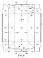
- the blank 1 comprises a rectangular bottom panel 10 with a pair of side wall panel means and a pair of end wall panel means joined thereto.
- Each side wall panel means comprises a first side wall panel 11 (12) foldably connected to a side 13 (14) of the bottom panel 10 and a second side wall panel 15 (16) foldably connected to its associated first side wall panel 11 (12) along fold line 17 (18).
- Each second side wall panel 15 (16) has end flaps or panels 19 and 20 (21 and 22) foldably connected thereto about fold lines 23 and 24 (25 and 26), respectively.
- Each end wall panel means comprises a first end wall panel 27 (28) foldably connected to an end 29 (30) of the bottom panel, and a second end wall panel 31 (32) foldably connected to the first end wall panel 27 (28) about a pair of closely spaced apart fold lines 33,34 (35,36).
- the second end wall panels 31 and 32 are divided along fold lines 39 and 40, respectively, into inner and outer portions 37a, 37b and 38a, 38b.
- the upper face (as viewed in Figure 1 ) of the blank 1 has double-sided self-adhesive strips 41 and 42 provided on the portions 37b and 38b, respectively. These self adhesive strips 41 and 42 are covered by removable non-adhesive release covering strips.
- gusset means 43 At each of the four corners of the bottom panel there is a gusset means generally designated 43-46, respectively, only one (gusset means 43) of which will be described in detail hereinafter.
- the gusset means 43 comprises a pair of gusset panels 43a and 43b separated by a diagonal fold line 43c.
- Gusset panel 43a is foldably joined to the first end wall panel 27 about fold line 43d and gusset panel 43b is foldably connected to the first side wall panel 11 and the end panel 19 along fold lines 43e and 43f, respectively.
- Figures 3 to 6 show various stages in the erection of an open-topped container from the blank 1.
- Figure 3 shows initial stages of the folding of one of the side wall panel means and one of the end wall panel means relative to the bottom panel 10.
- Figure 4 it can be seen how the second side wall panels 15 and 16 are folded outwardly back against first side wall panels 11 and 12, respectively to form double thickness side walls.
- Figures 4 to 6 it can be seen how the end flaps or panels 19-22 and gusset means 43-46 are folded flat against the outside of the respective first end wall panels 27 and 28 to form at least double thickness end walls for the open-topped container.
- the release covering strips are removed from the self-adhesive strips 41 and 42, the outer portions 37b and 38b of the end wall panels 31 and 32 are folded back against the inner portions 37a and 38a, respectively, of the end wall panels 131 and 32 and the folded over panels 31, 37 and 32, 38 are pressed against the underlying end panels 19, 21 and 20, 22 to be adhered thereto by the self-adhesive strips 41 and 42 (see Figure 6 ).
- the blank 2 comprises a rectangular top panel 50 having side panels 51 and 52 foldably joined to the top panel along sides 53 and 54, respectively, and end panels 55 and 56 foldably joined to the top panel along ends 57 and 58, respectively.
- End flaps 59, 60 and 61, 62 are foldably joined to opposite ends of the end panels 55 and 56, respectively.
- Double-sided adhesive tape is adhered to opposite side regions of the blank 2 to provide parallel adhesive strips 63 and 64 on side panels 51 and 52, respectively, and parallel adhesive strips 65-68 on end flaps 59-62, respectively.
- the outer adhesive layer is covered by a suitable removable covering strip.
- the top 4 is erected from the blank 2.
- the top is not pre-erected but instead is positioned with the top panel 50 over the top of the open topped container.
- the end panels are then folded downwardly against the end walls of the container, the covering strip is removed from the adhesive strips 65-67 and the flaps 59-62 are folded against, and adhered to, the side walls of the container.
- the removable covering strips are removed from the adhesive strips 63 and 64 and the side panels 51 and 52 are folded downwardly against, and adhered to, the side walls of the container (see Figure 7 ).
- Figures 8 and 9 show alternative first and second blanks respectively. Reference numerals in Figures 8 and 9 correspond to those in Figures 1 to 7 but with the addition of 100.
- Figure 8 shows an alternative first blank 101, which is largely similar to the first blank 1 of Figure 1 .
- the main difference is that the end flaps 119 to 122 of the alternative first blank 101 are elongated in the longitudinal direction of the blank. This means that when the blank is erected into a container, end flaps 119 and 121 overlap and end flaps 120 and 122 overlap. This provides additional strength to the ends of the container and helps in preventing buckling of the ends when the full container is pulled in a longitudinal direction.
- Figure 9 shows an alternative second blank 102 which comprises a rectangular top panel 150 having side panels 151 and 152 foldably joined to the top panel along sides 153 and 154, respectively, and end panels 155 and 156 foldably joined to the top panel along ends 157 and 158, respectively.
- End flaps 159,160 and 161, 162 are foldably joined to opposite ends of the side panels 151 and 152 respectively.
- Double-sided adhesive tape is adhered to opposite side regions of the blank 102 to provide an adhesive strip 163 running along side panel 151 and end flaps 159, 161, and a parallel adhesive strip 164 running along side panel 152 and end flaps 160, 162.
- the outer adhesive layer is covered by a suitable removable covering strip.
- a top is erected from the blank 102. Either the top may be pre-erected or the blank 102 may be positioned with the top panel 150 over the top of the open topped container.
- the end panels 155,156 are then folded downwardly against the end walls of the container.
- the covering strip is removed from the adhesive strips 163, 164 and the side panels 151, 152 are folded downwardly against, and adhered to, the side walls of the container.
- the end flaps 159-162 are then folded against, and adhered to, the end panels 155,156.
- the side and end walls provided by the open-topped container and the lid or top each have at least three thicknesses of blank material to provide good thermal insulation to any contents of the container.
- the open topped container would be packed with suitable products, such as fresh fish and optionally also ice, and would be closed by the'top erected from the blank 2 or 102.
- suitable products such as fresh fish and optionally also ice
- the blanks 1 and 2 or 101 and 102 can be kept in their unerected flat storage condition until a container is required to be used. Storage space is therefore not taken up by erected, non-filled containers.
- One particular advantage of the erected open-topped container is that the construction is intended to protect any open ended flutes of the corrugated sheet material from contact/exposure to ice or water when it is being packed. Normally during packing ice is thrown in on top of the packed contents in a haphazard manner.
- edge fluting there is a minimum of exposure of the edge fluting with inner and outer protective layers throughout the design. In particular, none of the upper edges of the upstanding walls has exposed edge fluting.
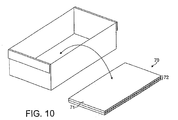
- an absorbent member 70 may be positioned in the bottom of the erected open-topped container before the container is filled with products.
- the absorbent member 70 has a liquid-impervious, e.g. plastics, top layer 71 and an absorbent bottom layer 72 typically comprising a number, e.g. from 3 to 5, layers of paper, one or more layers of corrugated cardboard or other absorbent material.
- the purpose of the absorbent member 70 is to provide an absorbent pad at the bottom of the container for absorbing liquids, e.g. melted ice and blood from stored produce such as fish, to prevent the stored product from "swimming" in fluid.
- the absorbent member 70 is sized to be similar to the bottom of the container so that there are no gaps, or only small gaps, between the edge of the absorbent pad and the walls of the container.
- the liquid-impervious top layer 71 provides a virtually dry surface or barrier on which the product to be packaged is supported.
- the absorbent member or "pad” may incorporate a bactericide for controlling possible harmful bacteria, such as salmonella, listeria, and leionella.
- the bactericide or other substance may be impregnated in the paper or incorporated in glue or other material of the absorbent pad.
- Figure 11 shows a further alternative first blank 201, which is largely similar to the blank 101 of Figure 8 .
- second end wall panels 231, 232 of the blank of Figure 11 are wider than the corresponding second end wall panels of Figure 8 .
- tabs 280, 281 are provided at the centre of the free edges of the second end wall panels 231, 232 respectively.
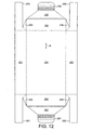
- FIG 12 shows a further alternative lid blank 202.
- This has panels which correspond to those of the lid blank 102 of Figure 9 (and designated by reference numerals with the addition of 100).
- triangular corner pieces 285 connect end panels 255, 256 to end flaps 259-262.
- the end flaps 259-262 are elongated.
- End tabs 290, 291 are provided on second end wall panels 292, 293 of the lid blank which are connected by crease lines to the first end wall panels 255, 256 respectively.
- the side wall panels 251, 252 and the end wall panels 255, 256 are folded downwardly from the top panel 250.
- the end flaps 259-262 and triangular pieces 285 are folded to create gusseted corners thus preventing leakage even when the closed container is inverted.
- the end flaps 259-262 of the lid blank are folded inside the first end wall panels 255,256; Second end wall panels 292, 293 are then folded inwardly and upwardly over the end flaps 259-262 and tabs 290, 291 are tucked over and behind the end flaps.
- the second end wall panels 231, 232 of the base press against the second end wall panels 292, 293 of the lid and provide a tight fit
- Figures 13 and 14 show base and lid blanks respectively having an enhanced engagement between the lid and base when erected.
- the second end wall panels 331, 332 of the base and the second end wall panels 392, 393 of the lid are narrower than the corresponding panels shown in Figures 11 and 12 .
- the base end flaps 319-322, and the outermost parts of the lid end flaps 359-362 are narrower so that tabs 380, 381, 390, 391, can still be tucked therebehind respectively.
- a lid erected from the blank of Figure 14 has its second end wall panels 392, 393 extending upwardly inside the first end panels 355, 356 over only a part, for example about half, of the height thereof.
- a base erected from the blank of Figure 13 has its second end wall panels 331, 332 extending upwardly inside the first end panels 355, 356 over only a part, of the height thereof, preferably about the same extent as the part of lid first end panels 355, 356 which are not covered by lid second end wall panels 331, 332.
- end tabs 280, 281, 290, 291, 380, 381, 390, 391 are omitted and securing of the second end wall panels could be achieved solely by adhesive means.
- drainage holes may be provided.
- drainage holes 95 can be provided at the crease between the bottom panel and the walls (here the end walls) of the container base.
- Simply providing a hole in the corrugated sheet material may be unacceptable because of the possible ingress of fluid into the flutes of the material.
- water resistant films preferably in the form of adhesive patches 96 having drainage apertures 97, are applied to the holes.
- the patches 96 are applied to both sides of the blank and prevent fluid reaching the edges of the holes 95 that would otherwise be exposed.
- thermally insulating blanks may be positioned in the bottom of the erected open-topped container before the latter is filled with products and on top of the filled container just before the lid is fitted over the container. In this way, additional thermally insulating layers can be provided on the bottom and top of the container.
- a light and heat reflective layer at least on the surface of the blank 2, 102, 202 or 302 destined to form the outside of the lid or top, improves the thermal insulating properties of the top.
- corrugated fibreboard/cardboard is the presently preferred material for the enclosure it may be made, for example, of double skinned fluted polypropylene copolymer or of other stiff yet foldable sheet material which may or may not be corrugated or fluted and which may comprise plastics materials, e.g. EVA (ethylene vinyl acetate), EPS (polyform) or PVC.
- EVA ethylene vinyl acetate
- EPS polyform
- PVC polyform
- an absorbent pad for inclusion in a fish box or other food product box and incorporating a bactericide.
Landscapes
- Engineering & Computer Science (AREA)
- Mechanical Engineering (AREA)
- Food Science & Technology (AREA)
- Cartons (AREA)
- Glass Compositions (AREA)
- Packages (AREA)
Claims (24)
- Flan (1, 101, 201) fabriqué en matériau en feuille rigide mais pliable pouvant être dressé en un corps formant récipient, comprenant :un panneau de fond rectangulaire (10, 110) ;une paire de moyens formant panneaux de paroi latérale comprenant chacun un premier panneau de paroi latérale (11, 12, 111, 112) relié de manière pliable à un côté associé du panneau de paroi de fond de façon à pouvoir être plié vers le haut à partir de celui-ci pour constituer une couche d'une paroi latérale, un second panneau de paroi latérale (15, 16, 115, 116) relié de manière pliable au premier panneau de paroi latérale de façon à pouvoir être replié contre ce dernier pour constituer une seconde couche de la paroi latérale, et des rabats d'extrémité (19, 20, 21, 22, 119, 120, 121, 122, 219, 220, 221, 222, 319, 320, 321, 322) reliés de manière pliable à des extrémités opposées du second panneau de paroi latérale ;une paire de moyens formant panneaux de paroi d'extrémité comprenant chacun un premier panneau de paroi d'extrémité (27, 28, 127, 128, 327, 328) relié de manière pliable à une extrémité associée du panneau de paroi de fond (10, 110) de façon à pouvoir être plié vers le haut à partir de celui-ci pour constituer une couche d'une paroi d'extrémité, et un second panneau de paroi d'extrémité (31, 32, 131, 132, 231, 331, 332) relié de manière pliable au premier panneau de paroi d'extrémité ; etdes moyens formant soufflet pliable (43, 44, 45, 46, 143, 144, 145, 146) à chaque angle du panneau de fond (10, 110) reliant des extrémités opposées de chacun des moyens formant panneaux de paroi latérale à des extrémités opposées desdits moyens formant panneaux de paroi d'extrémité ;moyennant quoi, dans le corps formant récipient dressé, les deux rabats d'extrémité (19, 20, 21, 22, 119, 120, 121, 122, 219, 220, 221, 222, 319, 320, 321, 322) associés à chaque extrémité du flan sont pliés contre le premier panneau de paroi d'extrémité associé (27, 28, 127, 128, 327, 328) pour constituer une seconde couche de la paroi d'extrémité et le second panneau de paroi d'extrémité (31, 32, 131, 132, 231, 331, 332) de chacun des moyens formant panneaux de paroi d'extrémité est replié au-dessus des rabats d'extrémité sous-jacents (19, 20, 21, 22, 119, 120, 121, 122, 219, 220, 221, 222, 319, 320, 321, 322) pour s'y rattacher ;caractérisé par des moyens adhésifs (41, 42, 141, 142) destinés à coller les seconds panneaux de paroi d'extrémité (31, 32, 131, 132, 231, 331, 332) aux rabats d'extrémité sous-jacents (19, 20, 21, 22, 119, 120, 121, 122, 219, 220, 221, 222, 319, 320, 321, 322).
- Flan selon la revendication 1, dans lequel chaque rabat d'extrémité (19, 20, 21, 22, 119, 120, 121, 122, 219, 220, 221, 222, 319, 320, 321, 322) est formé de façon à recouvrir l'autre rabat d'extrémité de la paire quand le flan est dressé en un corps formant récipient.
- Flan selon la revendication 1 ou 2, dans lequel les moyens adhésifs comprennent un ruban adhésif double-face (41, 42, 141, 142) dont une face est collée au flan (1, 101, 201) et l'autre face possède une pellicule non adhésive amovible.
- Flan selon la revendication 1, 2 ou 3, dans lequel les moyens adhésifs (41, 42, 141, 142) sont ménagés sur lesdits seconds panneaux de paroi d'extrémité (31, 32, 131, 132, 231, 331, 332).
- Flan selon l'une quelconque des revendications précédentes, dans lequel le matériau en feuille comprend un matériau ondulé.
- Flan selon la revendication 5, dans lequel ledit matériau ondulé comprend du carton-fibre ou du carton ondulé.
- Flan selon l'une quelconque des revendications précédentes, dans lequel le matériau en feuille est pourvu, sur ses deux faces, d'un revêtement résistant à l'eau ou d'un apprêt stratifié ou est imprégné d'une matière hydrophobe.
- Flan selon l'une quelconque des revendications précédentes, comprenant au moins un trou (95) agencé pour permettre l'évacuation de fluide dans le corps dressé.
- Flan selon la revendication 8, dans lequel ledit au moins un trou (95) comprend un trou dans le matériau en feuille rigide mais pliable et au moins un film résistant aux fluides (96) appliqué sur une périphérie du trou dans le matériau en feuille rigide mais pliable, de façon à permettre à un fluide de s'écouler par le trou (95) sans exposer ladite périphérie au fluide.
- Flan selon la revendication 9, dans lequel ledit au moins un trou (95) a une première couche de film résistant aux fluides (96) appliquée sur une première face du flan et une seconde couche de film résistant aux fluides (96) appliquée sur une seconde face du flan, les première et seconde couches de film ayant des ouvertures qui coïncident mutuellement (97) et qui permettent à un fluide de s'écouler par le trou (95).
- Jeu de flans fabriqués en matériau en feuille rigide mais pliable, comprenant un flan (1, 101, 201) selon une quelconque revendication précédente, pouvant être dressé en un corps formant récipient (3), et un flan de couvercle (2, 102) pouvant être dressé en un couvercle (4) dimensionné pour s'ajuster sur le corps formant récipient, le second panneau de paroi d'extrémité (31, 32, 131, 132, 231, 331, 332) de chacun des moyens formant panneaux de paroi d'extrémité étant agencé pour être espacé du premier panneau de paroi d'extrémité (27, 28, 127, 128, 327, 328) dans le corps dressé, de façon à venir en prise avec un panneau d'extrémité (55, 56, 155, 156, 255, 256, 355, 356) du couvercle (4) quand ce dernier est ajusté sur le corps dressé (3) afin de maintenir le couvercle ajusté de la sorte.
- Jeu de flans selon la revendication 11, dans lequel le second panneau de paroi d'extrémité (331, 332) du flan pouvant être dressé en corps et ledit panneau d'extrémité (355, 356) du flan de couvercle sont dimensionnés pour passer totalement l'un devant l'autre lors de l'ajustement du couvercle dressé sur le corps dressé, ledit panneau d'extrémité du flan de couvercle venant ensuite en prise sous un bord inférieur dudit second panneau de paroi d'extrémité (331, 332).
- Récipient ouvert en haut (3) dressé à partir d'un flan (1, 101, 201) selon l'une quelconque des revendications 1 à 10, comprenant un fond rectangulaire (10, 110), des parois latérales à double épaisseur s'étendant vers le haut à partir dudit fond, des parois d'extrémité à double épaisseur s'étendant vers le haut à partir dudit panneau de fond (10, 110), un soufflet (43, 44, 45, 46, 143, 144, 145, 146) à chaque angle du récipient reliant des extrémités opposées de chaque paroi latérale à des extrémités opposées des dites parois d'extrémité, des rabats d'extrémité (19, 20, 21, 22, 119, 120, 121, 122, 219, 220, 221, 222, 319, 320, 321, 322) reliés à des extrémités opposées de chaque paroi latérale et pliés avec les moyens formant soufflet contre les parois d'extrémité, et des moyens de liaison (41, 42, 141, 142), habituellement des moyens adhésifs, reliant les rabats d'extrémité aux parois d'extrémité.
- Récipient selon la revendication 13, ayant un couvercle (4).
- Récipient selon la revendication 14, dans lequel ledit couvercle comprend un panneau de dessus rectangulaire (250), des parois latérales de couvercle (251, 252) s'étendant vers le bas à partir dudit panneau de dessus, des parois d'extrémité de couvercle à double épaisseur (255, 292, 256, 293, 355, 392, 356, 393) s'étendant vers le bas à partir dudit panneau de dessus (250), des moyens formant soufflet de couvercle (285) à chaque angle du couvercle reliant des extrémités opposées de chaque paroi latérale de couvercle (251, 252) à des extrémités opposées des dites parois d'extrémité de couvercle, des rabats d'extrémité de couvercle (259, 260, 261, 262, 359, 360, 361, 362) reliés à des extrémités opposées de chaque paroi latérale de couvercle et pliés avec les moyens formant soufflet de couvercle (285) contre les parois d'extrémité de couvercle (255, 292, 256, 293, 355, 392, 356, 393), et des moyens de liaison de couvercle (290, 291, 390, 391) reliant les rabats d'extrémité aux parois d'extrémité.
- Récipient selon la revendication 15, dans lequel le second panneau de paroi d'extrémité (231, 331, 332) de chacun des moyens formant panneaux de paroi d'extrémité du corps est espacé du premier panneau de paroi d'extrémité de façon à venir en prise avec un panneau d'extrémité de couvercle (255, 292, 256, 293, 355, 392, 356, 393) faisant partie de la paroi d'extrémité de couvercle quand cette dernière est ajustée sur le corps pour maintenir le couvercle ajusté de la sorte.
- Récipient selon la revendication 16, dans lequel le second panneau de paroi d'extrémité (331, 332) du corps et ledit panneau d'extrémité de couvercle (355, 392, 356, 393) sont dimensionnés pour passer totalement l'un devant l'autre lors de l'ajustement du couvercle sur le corps, ledit panneau d'extrémité du flan de couvercle venant alors en prise sous un bord inférieur dudit second panneau de paroi d'extrémité du corps.
- Récipient selon la revendication 14, 15, 16 ou 17, dans lequel ledit couvercle (4) est assemblé de manière adhésive aux dites parois latérales et/ou aux dites parois d'extrémité.
- Récipient selon l'une quelconque des revendications 14 à 18, dans lequel ledit couvercle (4) a une pellicule en feuille réfléchissante destinée à réfléchir les rayonnements de chaleur et de lumière extérieurs.
- Récipient selon l'une quelconque des revendications 13 à 19, et un élément absorbant (70) destiné à être positionné à l'intérieur du corps (3) au-dessus du panneau de fond (10, 110).
- Récipient selon la revendication 20, dans lequel l'élément absorbant (70) a les mêmes dimensions que le panneau de fond (10, 110) du récipient.
- Récipient selon la revendication 20 ou 21, dans lequel l'élément absorbant (70) a une couche supérieure imperméable aux liquides (71) et une couche inférieure absorbante (72).
- Récipient selon l'une quelconque des revendications 20 à 22, dans lequel l'élément absorbant (70) comprend un bactéricide.
- Procédé d'emballage de produits tels que des denrées alimentaires, comprenant les étapes consistant à dresser un corps formant récipient (3) à partir d'un flan (1, 101, 201) selon l'une quelconque des revendications 1 à 10, charger le corps formant récipient avec les produits à emballer, et fermer le corps formant récipient (3) par un couvercle (4) formé à partir d'un autre flan (2, 102).
Applications Claiming Priority (9)
| Application Number | Priority Date | Filing Date | Title |
|---|---|---|---|
| GB0227120A GB0227120D0 (en) | 2002-11-20 | 2002-11-20 | Container |
| GB0227120 | 2002-11-20 | ||
| GB0301951A GB0301951D0 (en) | 2002-11-20 | 2003-01-28 | Container |
| GB0301951 | 2003-01-28 | ||
| GB0309768A GB0309768D0 (en) | 2002-11-20 | 2003-04-29 | Container |
| GB0309768 | 2003-04-29 | ||
| GBGB0312438.5A GB0312438D0 (en) | 2002-11-20 | 2003-05-30 | Container |
| GB0312438 | 2003-05-30 | ||
| PCT/GB2003/005040 WO2004045971A2 (fr) | 2002-11-20 | 2003-11-19 | Contenant |
Publications (2)
| Publication Number | Publication Date |
|---|---|
| EP1578672A2 EP1578672A2 (fr) | 2005-09-28 |
| EP1578672B1 true EP1578672B1 (fr) | 2008-04-02 |
Family
ID=32329938
Family Applications (1)
| Application Number | Title | Priority Date | Filing Date |
|---|---|---|---|
| EP03775590A Expired - Lifetime EP1578672B1 (fr) | 2002-11-20 | 2003-11-19 | Contenant |
Country Status (8)
| Country | Link |
|---|---|
| US (1) | US20060151584A1 (fr) |
| EP (1) | EP1578672B1 (fr) |
| AT (1) | ATE391082T1 (fr) |
| AU (1) | AU2003283611A1 (fr) |
| CA (1) | CA2506861A1 (fr) |
| DE (1) | DE60320140T2 (fr) |
| ES (1) | ES2303908T3 (fr) |
| WO (1) | WO2004045971A2 (fr) |
Families Citing this family (25)
| Publication number | Priority date | Publication date | Assignee | Title |
|---|---|---|---|---|
| GB0917627D0 (en) * | 2009-10-08 | 2009-11-25 | Ds Smith Packaging Ltd | Packaging carton and lid |
| GB2539589B (en) | 2011-06-17 | 2017-04-19 | Berry Plastics Corp | Insulated container |
| WO2012174568A2 (fr) | 2011-06-17 | 2012-12-20 | Berry Plastics Corporation | Procédé pour former un contenant isolé présentant une illustration |
| CA2842325A1 (fr) | 2011-06-17 | 2013-07-04 | Chris K. LESER | Manchon isole pour tasse |
| KR20140059255A (ko) | 2011-08-31 | 2014-05-15 | 베리 플라스틱스 코포레이션 | 단열 용기용 고분자 재료 |
| FR2988705B1 (fr) * | 2012-03-30 | 2014-05-09 | Saica Pack Sl | Emballage de conservation et de transport de produits frais |
| US8596520B2 (en) * | 2012-04-16 | 2013-12-03 | International Paper Co. | Waterproof and anti-wicking corrugated container |
| EP2888092A4 (fr) | 2012-08-07 | 2016-03-23 | Berry Plastics Corp | Procédé et machine de formation de coupe |
| MX2015005207A (es) | 2012-10-26 | 2016-03-21 | Berry Plastics Corp | Material polimerico para un recipiente aislado. |
| US9840049B2 (en) | 2012-12-14 | 2017-12-12 | Berry Plastics Corporation | Cellular polymeric material |
| AR093943A1 (es) | 2012-12-14 | 2015-07-01 | Berry Plastics Corp | Reborde de un envase termico |
| AR093944A1 (es) | 2012-12-14 | 2015-07-01 | Berry Plastics Corp | Troquelado para envase |
| US9957365B2 (en) | 2013-03-13 | 2018-05-01 | Berry Plastics Corporation | Cellular polymeric material |
| US9725202B2 (en) | 2013-03-14 | 2017-08-08 | Berry Plastics Corporation | Container |
| US10160593B2 (en) | 2013-07-05 | 2018-12-25 | Visy R & D Pty Ltd | Container for reducing deterioration of horticultural produce |
| WO2015024018A1 (fr) | 2013-08-16 | 2015-02-19 | Berry Plastics Corporation | Matériau polymère pour contenant isolé |
| US9758655B2 (en) | 2014-09-18 | 2017-09-12 | Berry Plastics Corporation | Cellular polymeric material |
| NL2013818B1 (en) * | 2014-11-14 | 2016-10-07 | Bioboxx Trading B V | Box and box holding frame suitable for waste. |
| FR3029509B1 (fr) * | 2014-12-05 | 2017-08-11 | Mecaflor | Emballage notamment pour fleurs coupees |
| WO2016118838A1 (fr) | 2015-01-23 | 2016-07-28 | Berry Plastics Corporation | Matériau polymère pour contenant isotherme |
| US11091311B2 (en) | 2017-08-08 | 2021-08-17 | Berry Global, Inc. | Insulated container and method of making the same |
| SE544410C2 (en) * | 2018-05-25 | 2022-05-10 | Stora Enso Oyj | Package and blank |
| GB202008550D0 (en) * | 2020-06-05 | 2020-07-22 | Softbox Systems Ltd | A wet cold chain distribution system and apparatus therefor |
| FR3113853B1 (fr) * | 2020-09-07 | 2023-08-25 | Sven Holtzinger | Dispositif de protection et de rétention de fluide notamment pour machine-outil ou réservoir portable |
| WO2023081598A1 (fr) * | 2021-11-02 | 2023-05-11 | The Coleman Company, Inc. | Refroidisseur à ondulations |
Family Cites Families (28)
| Publication number | Priority date | Publication date | Assignee | Title |
|---|---|---|---|---|
| US1601625A (en) * | 1926-01-26 | 1926-09-28 | Charles D Ordway | Fruit preserving and shipping package |
| GB453180A (en) * | 1934-12-21 | 1936-09-07 | Henri Thiolat | Improvements relating to the manufacture of cardboard and like boxes |
| GB614444A (en) * | 1944-11-20 | 1948-12-15 | Cartonnage D Echantillonage Et | Improved method of manufacturing foldable cardboard boxes |
| US2495807A (en) * | 1946-09-09 | 1950-01-31 | Sutherland Paper Co | Double walled box or carton |
| US2688433A (en) * | 1952-03-18 | 1954-09-07 | Charles Dreifus Jr | Container |
| US2954913A (en) * | 1957-07-19 | 1960-10-04 | Norton L Rossman | Insulating container |
| US3342401A (en) * | 1966-05-20 | 1967-09-19 | Union Camp Corp | Iced pack shipping box |
| US3531041A (en) * | 1968-01-31 | 1970-09-29 | John J Rohde | Carton |
| US3511429A (en) * | 1968-04-23 | 1970-05-12 | Crown Zellerbach Corp | Portable beverage cooler |
| US3536249A (en) * | 1968-10-02 | 1970-10-27 | St Joe Paper Co | Container with outfolded flanges |
| US3917155A (en) * | 1972-03-02 | 1975-11-04 | Robert P Bemiss | Carton |
| US3876131A (en) * | 1973-07-02 | 1975-04-08 | Hoerner Waldorf Corp | Wedge shaped carton |
| US4003514A (en) * | 1976-01-21 | 1977-01-18 | Olinkraft, Inc. | Frozen food tray |
| GB1593730A (en) * | 1977-12-15 | 1981-07-22 | Corruplast Ltd | Blank for making a box and a box made from the blank |
| US4260098A (en) * | 1979-05-07 | 1981-04-07 | Federal Paper Board Company, Inc. | Tray container with reinforced sidewalls |
| FR2576874B1 (fr) * | 1985-02-04 | 1987-10-02 | Socar | Conditionnement porteur etanche a l'humidite et aux gaz et obturable par un film de matiere plastique |
| US4582247A (en) * | 1985-05-31 | 1986-04-15 | Container Corporation Of America | Rounded corner locking carton lid |
| US5495727A (en) * | 1994-04-22 | 1996-03-05 | Strong; Bryan | Container and expandable cooler |
| US6171695B1 (en) * | 1994-09-21 | 2001-01-09 | Kimberly-Clark Worldwide, Inc. | Thin absorbent pads for food products |
| US5752648A (en) * | 1996-06-19 | 1998-05-19 | International Paper | Web bottomed eight sided tray |
| US6145175A (en) * | 1998-02-23 | 2000-11-14 | Batesville Services, Inc. | Modular casket |
| US5967407A (en) * | 1998-08-27 | 1999-10-19 | Mueller; Charles J. | Auto-erecting box |
| US6338234B1 (en) * | 1999-11-24 | 2002-01-15 | Weyerhauser Company | Method of encapsulating shipping container blanks in plastic film |
| NL1014270C2 (nl) * | 2000-02-02 | 2001-08-03 | Smurfit Solidpack B V | Opzetbare doos. |
| US20020079238A1 (en) * | 2000-12-22 | 2002-06-27 | Wilson Ollie B. | Bag with absorbent pad |
| US6695138B1 (en) * | 2001-07-16 | 2004-02-24 | Commodaic Machine Co. Inc. | Food package with integral juice absorbing bottom |
| US6736309B1 (en) * | 2001-11-16 | 2004-05-18 | Wes-Pak, Inc. | Quick erecting foldable portable cooler |
| NL1019538C1 (nl) * | 2001-12-11 | 2002-03-12 | V O F Vrinten & Lohman | Plano voor een dubbelwandige doos en vouwinrichting voor het vouwen van een plano. |
-
2003
- 2003-11-19 CA CA002506861A patent/CA2506861A1/fr not_active Abandoned
- 2003-11-19 DE DE60320140T patent/DE60320140T2/de not_active Expired - Lifetime
- 2003-11-19 AT AT03775590T patent/ATE391082T1/de not_active IP Right Cessation
- 2003-11-19 AU AU2003283611A patent/AU2003283611A1/en not_active Abandoned
- 2003-11-19 US US10/535,960 patent/US20060151584A1/en not_active Abandoned
- 2003-11-19 EP EP03775590A patent/EP1578672B1/fr not_active Expired - Lifetime
- 2003-11-19 ES ES03775590T patent/ES2303908T3/es not_active Expired - Lifetime
- 2003-11-19 WO PCT/GB2003/005040 patent/WO2004045971A2/fr active IP Right Grant
Also Published As
| Publication number | Publication date |
|---|---|
| AU2003283611A8 (en) | 2004-06-15 |
| DE60320140D1 (de) | 2008-05-15 |
| WO2004045971A2 (fr) | 2004-06-03 |
| AU2003283611A1 (en) | 2004-06-15 |
| CA2506861A1 (fr) | 2004-06-03 |
| ES2303908T3 (es) | 2008-09-01 |
| EP1578672A2 (fr) | 2005-09-28 |
| DE60320140T2 (de) | 2009-05-20 |
| ATE391082T1 (de) | 2008-04-15 |
| US20060151584A1 (en) | 2006-07-13 |
| WO2004045971A3 (fr) | 2004-08-12 |
Similar Documents
| Publication | Publication Date | Title |
|---|---|---|
| EP1578672B1 (fr) | Contenant | |
| US3756495A (en) | Boilable bakeable package | |
| US4754914A (en) | Package for wrapping food or other articles | |
| US4628863A (en) | Disposable cat litter box | |
| US2983421A (en) | Compartmented carton | |
| US4804137A (en) | Food container | |
| US4241863A (en) | Container with multiple compartments | |
| CN214139311U (zh) | 用于新鲜产品运输的瓦楞纸箱 | |
| US3064876A (en) | Ornamental wrapped box | |
| US4165030A (en) | Two cell bulk box | |
| US5265796A (en) | Plural compartment carton food tray with improved corner construction | |
| WO2021250623A1 (fr) | Ébauche et emballage | |
| CA1095857A (fr) | Contenant d'expedition et distributeur a l'epreuve des pertes | |
| US4802620A (en) | Gable top carton for preventing wicking | |
| JP2006213386A (ja) | 配送用箱 | |
| KR200496512Y1 (ko) | 골판지의 누출방지 및 액밀 포장 박스 | |
| US3501084A (en) | Packaging structures | |
| US3077709A (en) | Filling and sealing method | |
| JP2526408Y2 (ja) | 保冷防水包装体 | |
| DK167059B1 (da) | Vandfast kasse- eller laagemne | |
| GB2407809A (en) | Collapsible container | |
| JP3018048U (ja) | 紙製容器 | |
| US20230105561A1 (en) | Insulating packaging for crustaceans | |
| US20210253295A1 (en) | Fold flat tray and associated method of forming | |
| GB2328679A (en) | Containers for moist products such as shellfish |
Legal Events
| Date | Code | Title | Description |
|---|---|---|---|
| PUAI | Public reference made under article 153(3) epc to a published international application that has entered the european phase |
Free format text: ORIGINAL CODE: 0009012 |
|
| 17P | Request for examination filed |
Effective date: 20050530 |
|
| AK | Designated contracting states |
Kind code of ref document: A2 Designated state(s): AT BE BG CH CY CZ DE DK EE ES FI FR GB GR HU IE IT LI LU MC NL PT RO SE SI SK TR |
|
| AX | Request for extension of the european patent |
Extension state: AL LT LV MK |
|
| DAX | Request for extension of the european patent (deleted) | ||
| 17Q | First examination report despatched |
Effective date: 20060529 |
|
| GRAP | Despatch of communication of intention to grant a patent |
Free format text: ORIGINAL CODE: EPIDOSNIGR1 |
|
| GRAS | Grant fee paid |
Free format text: ORIGINAL CODE: EPIDOSNIGR3 |
|
| GRAA | (expected) grant |
Free format text: ORIGINAL CODE: 0009210 |
|
| AK | Designated contracting states |
Kind code of ref document: B1 Designated state(s): AT BE BG CH CY CZ DE DK EE ES FI FR GB GR HU IE IT LI LU MC NL PT RO SE SI SK TR |
|
| REG | Reference to a national code |
Ref country code: GB Ref legal event code: FG4D |
|
| REG | Reference to a national code |
Ref country code: CH Ref legal event code: EP Ref country code: IE Ref legal event code: FG4D |
|
| REF | Corresponds to: |
Ref document number: 60320140 Country of ref document: DE Date of ref document: 20080515 Kind code of ref document: P |
|
| REG | Reference to a national code |
Ref country code: ES Ref legal event code: FG2A Ref document number: 2303908 Country of ref document: ES Kind code of ref document: T3 |
|
| REG | Reference to a national code |
Ref country code: GR Ref legal event code: EP Ref document number: 20080401698 Country of ref document: GR |
|
| PG25 | Lapsed in a contracting state [announced via postgrant information from national office to epo] |
Ref country code: SI Free format text: LAPSE BECAUSE OF FAILURE TO SUBMIT A TRANSLATION OF THE DESCRIPTION OR TO PAY THE FEE WITHIN THE PRESCRIBED TIME-LIMIT Effective date: 20080402 |
|
| NLV1 | Nl: lapsed or annulled due to failure to fulfill the requirements of art. 29p and 29m of the patents act | ||
| REG | Reference to a national code |
Ref country code: FR Ref legal event code: RN |
|
| PG25 | Lapsed in a contracting state [announced via postgrant information from national office to epo] |
Ref country code: BG Free format text: LAPSE BECAUSE OF FAILURE TO SUBMIT A TRANSLATION OF THE DESCRIPTION OR TO PAY THE FEE WITHIN THE PRESCRIBED TIME-LIMIT Effective date: 20080702 Ref country code: FI Free format text: LAPSE BECAUSE OF FAILURE TO SUBMIT A TRANSLATION OF THE DESCRIPTION OR TO PAY THE FEE WITHIN THE PRESCRIBED TIME-LIMIT Effective date: 20080402 Ref country code: NL Free format text: LAPSE BECAUSE OF FAILURE TO SUBMIT A TRANSLATION OF THE DESCRIPTION OR TO PAY THE FEE WITHIN THE PRESCRIBED TIME-LIMIT Effective date: 20080402 Ref country code: PT Free format text: LAPSE BECAUSE OF FAILURE TO SUBMIT A TRANSLATION OF THE DESCRIPTION OR TO PAY THE FEE WITHIN THE PRESCRIBED TIME-LIMIT Effective date: 20080903 |
|
| REG | Reference to a national code |
Ref country code: FR Ref legal event code: FC |
|
| EN | Fr: translation not filed | ||
| PG25 | Lapsed in a contracting state [announced via postgrant information from national office to epo] |
Ref country code: AT Free format text: LAPSE BECAUSE OF FAILURE TO SUBMIT A TRANSLATION OF THE DESCRIPTION OR TO PAY THE FEE WITHIN THE PRESCRIBED TIME-LIMIT Effective date: 20080402 |
|
| ET | Fr: translation filed | ||
| EN | Fr: translation not filed | ||
| PG25 | Lapsed in a contracting state [announced via postgrant information from national office to epo] |
Ref country code: CZ Free format text: LAPSE BECAUSE OF FAILURE TO SUBMIT A TRANSLATION OF THE DESCRIPTION OR TO PAY THE FEE WITHIN THE PRESCRIBED TIME-LIMIT Effective date: 20080402 Ref country code: DK Free format text: LAPSE BECAUSE OF FAILURE TO SUBMIT A TRANSLATION OF THE DESCRIPTION OR TO PAY THE FEE WITHIN THE PRESCRIBED TIME-LIMIT Effective date: 20080402 Ref country code: SE Free format text: LAPSE BECAUSE OF FAILURE TO SUBMIT A TRANSLATION OF THE DESCRIPTION OR TO PAY THE FEE WITHIN THE PRESCRIBED TIME-LIMIT Effective date: 20080702 |
|
| PLBE | No opposition filed within time limit |
Free format text: ORIGINAL CODE: 0009261 |
|
| STAA | Information on the status of an ep patent application or granted ep patent |
Free format text: STATUS: NO OPPOSITION FILED WITHIN TIME LIMIT |
|
| PG25 | Lapsed in a contracting state [announced via postgrant information from national office to epo] |
Ref country code: SK Free format text: LAPSE BECAUSE OF FAILURE TO SUBMIT A TRANSLATION OF THE DESCRIPTION OR TO PAY THE FEE WITHIN THE PRESCRIBED TIME-LIMIT Effective date: 20080402 Ref country code: BE Free format text: LAPSE BECAUSE OF FAILURE TO SUBMIT A TRANSLATION OF THE DESCRIPTION OR TO PAY THE FEE WITHIN THE PRESCRIBED TIME-LIMIT Effective date: 20080402 Ref country code: RO Free format text: LAPSE BECAUSE OF FAILURE TO SUBMIT A TRANSLATION OF THE DESCRIPTION OR TO PAY THE FEE WITHIN THE PRESCRIBED TIME-LIMIT Effective date: 20080402 |
|
| 26N | No opposition filed |
Effective date: 20090106 |
|
| PG25 | Lapsed in a contracting state [announced via postgrant information from national office to epo] |
Ref country code: EE Free format text: LAPSE BECAUSE OF FAILURE TO SUBMIT A TRANSLATION OF THE DESCRIPTION OR TO PAY THE FEE WITHIN THE PRESCRIBED TIME-LIMIT Effective date: 20080402 |
|
| PG25 | Lapsed in a contracting state [announced via postgrant information from national office to epo] |
Ref country code: MC Free format text: LAPSE BECAUSE OF NON-PAYMENT OF DUE FEES Effective date: 20081130 |
|
| REG | Reference to a national code |
Ref country code: CH Ref legal event code: PL |
|
| PG25 | Lapsed in a contracting state [announced via postgrant information from national office to epo] |
Ref country code: IT Free format text: LAPSE BECAUSE OF FAILURE TO SUBMIT A TRANSLATION OF THE DESCRIPTION OR TO PAY THE FEE WITHIN THE PRESCRIBED TIME-LIMIT Effective date: 20080402 |
|
| PG25 | Lapsed in a contracting state [announced via postgrant information from national office to epo] |
Ref country code: CY Free format text: LAPSE BECAUSE OF FAILURE TO SUBMIT A TRANSLATION OF THE DESCRIPTION OR TO PAY THE FEE WITHIN THE PRESCRIBED TIME-LIMIT Effective date: 20080402 |
|
| PG25 | Lapsed in a contracting state [announced via postgrant information from national office to epo] |
Ref country code: CH Free format text: LAPSE BECAUSE OF NON-PAYMENT OF DUE FEES Effective date: 20081130 Ref country code: LI Free format text: LAPSE BECAUSE OF NON-PAYMENT OF DUE FEES Effective date: 20081130 |
|
| PG25 | Lapsed in a contracting state [announced via postgrant information from national office to epo] |
Ref country code: HU Free format text: LAPSE BECAUSE OF FAILURE TO SUBMIT A TRANSLATION OF THE DESCRIPTION OR TO PAY THE FEE WITHIN THE PRESCRIBED TIME-LIMIT Effective date: 20081003 Ref country code: LU Free format text: LAPSE BECAUSE OF NON-PAYMENT OF DUE FEES Effective date: 20081119 |
|
| PG25 | Lapsed in a contracting state [announced via postgrant information from national office to epo] |
Ref country code: TR Free format text: LAPSE BECAUSE OF FAILURE TO SUBMIT A TRANSLATION OF THE DESCRIPTION OR TO PAY THE FEE WITHIN THE PRESCRIBED TIME-LIMIT Effective date: 20080402 |
|
| REG | Reference to a national code |
Ref country code: FR Ref legal event code: EERR Free format text: CORRECTION DE BOPI 09/04 - 3.2. Ref country code: FR Ref legal event code: EERR Free format text: CORRECTION DE BOPI 08/48 - 3.2. |
|
| PGFP | Annual fee paid to national office [announced via postgrant information from national office to epo] |
Ref country code: IE Payment date: 20121120 Year of fee payment: 10 Ref country code: FR Payment date: 20121130 Year of fee payment: 10 |
|
| PGFP | Annual fee paid to national office [announced via postgrant information from national office to epo] |
Ref country code: ES Payment date: 20121116 Year of fee payment: 10 Ref country code: GR Payment date: 20121112 Year of fee payment: 10 Ref country code: GB Payment date: 20121129 Year of fee payment: 10 |
|
| PGFP | Annual fee paid to national office [announced via postgrant information from national office to epo] |
Ref country code: DE Payment date: 20130114 Year of fee payment: 10 |
|
| REG | Reference to a national code |
Ref country code: DE Ref legal event code: R119 Ref document number: 60320140 Country of ref document: DE |
|
| GBPC | Gb: european patent ceased through non-payment of renewal fee |
Effective date: 20131119 |
|
| REG | Reference to a national code |
Ref country code: GR Ref legal event code: ML Ref document number: 20080401698 Country of ref document: GR Effective date: 20140603 |
|
| REG | Reference to a national code |
Ref country code: FR Ref legal event code: ST Effective date: 20140731 |
|
| REG | Reference to a national code |
Ref country code: IE Ref legal event code: MM4A |
|
| PG25 | Lapsed in a contracting state [announced via postgrant information from national office to epo] |
Ref country code: GR Free format text: LAPSE BECAUSE OF NON-PAYMENT OF DUE FEES Effective date: 20140603 Ref country code: DE Free format text: LAPSE BECAUSE OF NON-PAYMENT OF DUE FEES Effective date: 20140603 |
|
| REG | Reference to a national code |
Ref country code: DE Ref legal event code: R119 Ref document number: 60320140 Country of ref document: DE Effective date: 20140603 |
|
| PG25 | Lapsed in a contracting state [announced via postgrant information from national office to epo] |
Ref country code: IE Free format text: LAPSE BECAUSE OF NON-PAYMENT OF DUE FEES Effective date: 20131119 |
|
| PG25 | Lapsed in a contracting state [announced via postgrant information from national office to epo] |
Ref country code: FR Free format text: LAPSE BECAUSE OF NON-PAYMENT OF DUE FEES Effective date: 20131202 Ref country code: GB Free format text: LAPSE BECAUSE OF NON-PAYMENT OF DUE FEES Effective date: 20131119 |
|
| REG | Reference to a national code |
Ref country code: ES Ref legal event code: FD2A Effective date: 20150709 |
|
| PG25 | Lapsed in a contracting state [announced via postgrant information from national office to epo] |
Ref country code: ES Free format text: LAPSE BECAUSE OF NON-PAYMENT OF DUE FEES Effective date: 20131120 |