EP1578555B1 - Method and system for cutting cores with a laser - Google Patents
Method and system for cutting cores with a laser Download PDFInfo
- Publication number
- EP1578555B1 EP1578555B1 EP03754609A EP03754609A EP1578555B1 EP 1578555 B1 EP1578555 B1 EP 1578555B1 EP 03754609 A EP03754609 A EP 03754609A EP 03754609 A EP03754609 A EP 03754609A EP 1578555 B1 EP1578555 B1 EP 1578555B1
- Authority
- EP
- European Patent Office
- Prior art keywords
- core
- laser beam
- laser
- delivery system
- beam delivery
- Prior art date
- Legal status (The legal status is an assumption and is not a legal conclusion. Google has not performed a legal analysis and makes no representation as to the accuracy of the status listed.)
- Expired - Lifetime
Links
- 238000005520 cutting process Methods 0.000 title claims description 29
- 238000000034 method Methods 0.000 title claims description 16
- 239000000463 material Substances 0.000 claims description 30
- 230000033001 locomotion Effects 0.000 claims description 17
- 239000000123 paper Substances 0.000 claims description 7
- 238000011144 upstream manufacturing Methods 0.000 claims description 7
- 239000011111 cardboard Substances 0.000 claims description 6
- 238000012423 maintenance Methods 0.000 claims description 4
- 238000004891 communication Methods 0.000 claims description 3
- 230000005484 gravity Effects 0.000 claims description 3
- 239000004033 plastic Substances 0.000 claims description 3
- 229920003023 plastic Polymers 0.000 claims description 3
- 238000007599 discharging Methods 0.000 claims description 2
- 239000007788 liquid Substances 0.000 claims description 2
- 239000004065 semiconductor Substances 0.000 claims description 2
- 239000000126 substance Substances 0.000 claims description 2
- 238000004140 cleaning Methods 0.000 claims 1
- 239000011094 fiberboard Substances 0.000 claims 1
- 239000011162 core material Substances 0.000 description 153
- 239000003292 glue Substances 0.000 description 19
- 238000004804 winding Methods 0.000 description 16
- 210000005069 ears Anatomy 0.000 description 9
- CURLTUGMZLYLDI-UHFFFAOYSA-N Carbon dioxide Chemical compound O=C=O CURLTUGMZLYLDI-UHFFFAOYSA-N 0.000 description 5
- 239000011087 paperboard Substances 0.000 description 5
- 229910002092 carbon dioxide Inorganic materials 0.000 description 4
- 239000001569 carbon dioxide Substances 0.000 description 4
- 230000000712 assembly Effects 0.000 description 3
- 238000000429 assembly Methods 0.000 description 3
- 239000000428 dust Substances 0.000 description 3
- 238000012986 modification Methods 0.000 description 3
- 230000004048 modification Effects 0.000 description 3
- 229910019655 synthetic inorganic crystalline material Inorganic materials 0.000 description 3
- XKRFYHLGVUSROY-UHFFFAOYSA-N Argon Chemical compound [Ar] XKRFYHLGVUSROY-UHFFFAOYSA-N 0.000 description 2
- 238000010521 absorption reaction Methods 0.000 description 2
- 230000001427 coherent effect Effects 0.000 description 2
- 230000007423 decrease Effects 0.000 description 2
- 238000013461 design Methods 0.000 description 2
- 239000007789 gas Substances 0.000 description 2
- CPBQJMYROZQQJC-UHFFFAOYSA-N helium neon Chemical compound [He].[Ne] CPBQJMYROZQQJC-UHFFFAOYSA-N 0.000 description 2
- 238000004519 manufacturing process Methods 0.000 description 2
- 239000007769 metal material Substances 0.000 description 2
- 230000003287 optical effect Effects 0.000 description 2
- 230000035515 penetration Effects 0.000 description 2
- 239000002861 polymer material Substances 0.000 description 2
- 230000008569 process Effects 0.000 description 2
- 238000012545 processing Methods 0.000 description 2
- 235000015842 Hesperis Nutrition 0.000 description 1
- 235000012633 Iberis amara Nutrition 0.000 description 1
- 229910052779 Neodymium Inorganic materials 0.000 description 1
- 229920005372 Plexiglas® Polymers 0.000 description 1
- 239000011149 active material Substances 0.000 description 1
- 239000000853 adhesive Substances 0.000 description 1
- 230000001070 adhesive effect Effects 0.000 description 1
- 230000002411 adverse Effects 0.000 description 1
- JNDMLEXHDPKVFC-UHFFFAOYSA-N aluminum;oxygen(2-);yttrium(3+) Chemical compound [O-2].[O-2].[O-2].[Al+3].[Y+3] JNDMLEXHDPKVFC-UHFFFAOYSA-N 0.000 description 1
- 238000013459 approach Methods 0.000 description 1
- 229910052786 argon Inorganic materials 0.000 description 1
- 239000011324 bead Substances 0.000 description 1
- 230000015572 biosynthetic process Effects 0.000 description 1
- 230000008859 change Effects 0.000 description 1
- 238000006243 chemical reaction Methods 0.000 description 1
- 239000011248 coating agent Substances 0.000 description 1
- 238000000576 coating method Methods 0.000 description 1
- 230000000295 complement effect Effects 0.000 description 1
- 239000013078 crystal Substances 0.000 description 1
- 238000005516 engineering process Methods 0.000 description 1
- 239000004744 fabric Substances 0.000 description 1
- 230000001815 facial effect Effects 0.000 description 1
- 239000000835 fiber Substances 0.000 description 1
- 150000002500 ions Chemical class 0.000 description 1
- 230000007246 mechanism Effects 0.000 description 1
- QEFYFXOXNSNQGX-UHFFFAOYSA-N neodymium atom Chemical compound [Nd] QEFYFXOXNSNQGX-UHFFFAOYSA-N 0.000 description 1
- 229910052755 nonmetal Inorganic materials 0.000 description 1
- 150000002843 nonmetals Chemical class 0.000 description 1
- 238000004806 packaging method and process Methods 0.000 description 1
- 239000004926 polymethyl methacrylate Substances 0.000 description 1
- 230000003252 repetitive effect Effects 0.000 description 1
- 238000005096 rolling process Methods 0.000 description 1
- 239000010979 ruby Substances 0.000 description 1
- 229910001750 ruby Inorganic materials 0.000 description 1
- 239000005336 safety glass Substances 0.000 description 1
- 238000009834 vaporization Methods 0.000 description 1
- 230000008016 vaporization Effects 0.000 description 1
- XLYOFNOQVPJJNP-UHFFFAOYSA-N water Substances O XLYOFNOQVPJJNP-UHFFFAOYSA-N 0.000 description 1
- 229910019901 yttrium aluminum garnet Inorganic materials 0.000 description 1
Images


Classifications
-
- B—PERFORMING OPERATIONS; TRANSPORTING
- B31—MAKING ARTICLES OF PAPER, CARDBOARD OR MATERIAL WORKED IN A MANNER ANALOGOUS TO PAPER; WORKING PAPER, CARDBOARD OR MATERIAL WORKED IN A MANNER ANALOGOUS TO PAPER
- B31C—MAKING WOUND ARTICLES, e.g. WOUND TUBES, OF PAPER, CARDBOARD OR MATERIAL WORKED IN A MANNER ANALOGOUS TO PAPER
- B31C11/00—Machinery for winding combined with other machinery
-
- B—PERFORMING OPERATIONS; TRANSPORTING
- B23—MACHINE TOOLS; METAL-WORKING NOT OTHERWISE PROVIDED FOR
- B23K—SOLDERING OR UNSOLDERING; WELDING; CLADDING OR PLATING BY SOLDERING OR WELDING; CUTTING BY APPLYING HEAT LOCALLY, e.g. FLAME CUTTING; WORKING BY LASER BEAM
- B23K26/00—Working by laser beam, e.g. welding, cutting or boring
- B23K26/08—Devices involving relative movement between laser beam and workpiece
- B23K26/0823—Devices involving rotation of the workpiece
-
- B—PERFORMING OPERATIONS; TRANSPORTING
- B23—MACHINE TOOLS; METAL-WORKING NOT OTHERWISE PROVIDED FOR
- B23K—SOLDERING OR UNSOLDERING; WELDING; CLADDING OR PLATING BY SOLDERING OR WELDING; CUTTING BY APPLYING HEAT LOCALLY, e.g. FLAME CUTTING; WORKING BY LASER BEAM
- B23K26/00—Working by laser beam, e.g. welding, cutting or boring
- B23K26/08—Devices involving relative movement between laser beam and workpiece
- B23K26/083—Devices involving movement of the workpiece in at least one axial direction
- B23K26/0838—Devices involving movement of the workpiece in at least one axial direction by using an endless conveyor belt
- B23K26/0846—Devices involving movement of the workpiece in at least one axial direction by using an endless conveyor belt for moving elongated workpieces longitudinally, e.g. wire or strip material
Definitions
- high-bulk rolled web products can adversely affect a cycle-rate capability of the machine. For instance, as roll bulks increase, rolled web product sheet counts, conversion process efficiencies, and a general throughput capability of the machine correspondingly decrease. Ironically, these decreases demand increased cycle-rates.
- Improvements in machine cycle-rates are hampered in one respect by a conventional core production process. Cores are produced, for instance, to wind up the rolled web products. However, cutter assemblies used to cut the cores to specific sizes have reached the limits of known technology. The typical cutter assembly uses saw blades and slitters that limit core production speed and efficiency and thus limit machine cycle-rates.
- a core is usually formed on a winding mandrel from unwind stations known as "unwinds".
- the core is often made of paper, paperboard, cardboard, and other windable materials.
- the unwinds unwind webs of the windable material onto a winding mandrel to form the core.
- glue is applied to one or more webs of the windable material, which are helically wound by a winding mandrel to form a continuous core.
- a downstream cutter assembly cuts the continuous core to specific lengths.
- One type of a cutter assembly is known to include a knife or saw blade disposed on a track assembly.
- the saw blade is positioned on the track assembly to directly contact the continuous core.
- the core is cut as the saw blade is moved across a circumferential surface of the core.
- a problem with this type of mechanical cutter assembly is that the saw blade becomes worn and dull over time. In addition to forming undesirable paper lint and dust, a dull saw blade eventually causes the core to be torn apart, rather than to be cut cleanly.
- Tom cores also occur when the saw blade lags behind or does not match the speed of the core.
- a drop in saw blade speed could occur due to a drop in air pressure in a mill or due to mechanical problems associated with bearings and cam followers in known cutter assemblies.
- tom cores result from faulty glue application during the core winding stage. Faulty glue application is caused by insufficient application of glue, missed areas in the overlap area of the windable material, and/or inconsistent glue absorption of the windable material.
- a water drop or absorption rate of the windable material, or a change in the glue viscosity can render the glue at least partially ineffective.
- the dull saw blade catches an ineffective glue seam in the overlap area, the core is tom and edges of the glued core are "kicked up.”
- Torn cores exhibit what are termed in the Industry as "pulled ears," tails, or flags. Whether caused by mechanical problems associated with conventional cutter assemblies, or due to faulty glue applications, pulled ears cause significant problems in a downstream machine direction. For instance, as a core is rotating at high speed and begins to wind up a sheet of the rolled web product, a pulled ear on the core can tear out the sheet and force a machine stoppage.
- a cutter assembly for cutting cores that is not susceptible to mechanical wear at the cutting point, which does not require machine downtime to clean up excess glue, and which results in a relatively smooth cut edge that is free of lint, dust and pulled ears is needed.
- the present invention provides a method according to claim 1 and system according to claim 19 for cutting cores.
- the cores are used as containers, base structures, or for rolling up rolled web products.
- the cores are made of paper, paperboard, cardboard, plastic, or any windable material suitable as containers, for winding up the rolled web products, or the like.
- the rolled web products include tissues, paper towels, industrial wipers, laboratory wipers, wet wipes, non-woven polymer materials, air-laid materials, wet materials, dry materials, disposable materials, nondisposable materials, treated materials, metallic materials and the like.
- the tissues include facial tissues or bath tissues, for instance, which are made predominantly of pulp fibers and can be creped or uncreped.
- the tissues can be formed from a web creped from a Yankee dryer.
- the tissues can be an uncreped, through-air-dried (TAD) fabric.
- TAD through-air-dried
- One embodiment of the present invention includes a laser, a beam delivery system, a linear motor, and a core guidance tube.
- the core guidance tube supports and guides the core while the beam delivery system redirects and focuses the laser beam onto the core to cut the core.
- the linear motor is used to move the beam delivery system to cut the core, which is continuously moving in a machine direction.
- the core is cut cleanly without mechanical contact.
- a method for cutting the core using a laser and a laser beam delivery system. Steps of this method include moving the laser beam delivery system in a machine direction substantially parallel to a moving core. The laser beam delivery system redirects and focuses the laser beam to cut the moving core without mechanically contacting the core.
- cutting the cores with a laser instead of mechanical devices reduces flags or pulled ears, prevents excessive machine downtime, and reduces glue usage by as much as 75%.
- the glue is applied as a narrow, focused ribbon.
- the ribbon of glue is applied to one or more parts of core material, which are helically wound to create glued edges or connecting junctures. The laser will cut cleanly through these junctures.
- a known saw blade can "kick up" an edge of the juncture and cause the machine to jam.
- the present invention is directed to a laser core cutting system that utilizes a laser to cut a helically wound object such as a core.
- the core is made of paper, paperboard, cardboard, plastic, or any windable material suitable for winding up tissues, paper towels, industrial wipers, laboratory wipers, wet wipes, non-woven polymer materials, air-laid materials, wet materials, dry materials, disposable materials, nondisposable materials, treated materials, metallic materials and the like.
- the core can be used as a container for shipping and mailing items, or as a base structure such as for model rockets, or for packaging foodstuffs, feminine care products, blueprints, maps, charts, and other assorted items.
- the laser core cutting system of the present invention avoids mechanical wear at a cutting point on the core material by eliminating a mechanical cutting mechanism.
- the laser core cutting system provides a relatively smooth cut edge on the core, free of lint, dust, and pulled ears.
- the laser core cutting system also reduces machine downtime required to clean up excess glue and remove downstream obstructions caused by pulled ears.
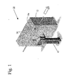
- a laser core cutting system 10 for cutting a core 12 is provided in accordance with one embodiment of the present invention. It should be understood, however, that various other arrangements of the laser core cutting system 10 can be made in accordance with the present invention. For instance, a plurality of the laser core cutting systems can be arranged in series or in parallel to accommodate multiple lines of continuous cores 12.
- the laser core cutting system 10 has a viewing window 10a through which an operator O can monitor operation of the laser core cutting system 10.
- the viewing window 10a is constructed of a known safety glass or a Plexiglas ® -type material that is resistant to physical impact and has optical qualities that protect the vision of the operator O. Viewing windows are known and further details are not necessary to appreciate this aspect of the invention.
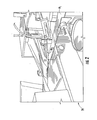
- the continuous core 12 is shown being formed and guided by a core guidance tube 24 in a machine (translational) direction D.
- the core guidance tube 24 receives the core 12 from an upstream winding mandrel 16 and positions the core 12 for cutting by the laser core cutting system 10.
- Figure 2 particularly shows the upstream winding mandrel 16 helically winding two webs W 1 , W 2 of windable material to form the core 12. More specifically, the core 12 is formed on the winding mandrel 16 from two or more conventional unwind stations or "unwinds" (not shown) in which the webs W 1 , W 2 are unwound from parent rolls (not shown) to the winding mandrel 16.
- the webs W 1 , W 2 enter the winding mandrel 16 at the same angle to form the helically wound core 12, although various entry angles can be arranged to wind-up nonstandard or custom wound cores. It is also to be understood that any number of webs of windable material can be used to form single-ply or multi-ply cores 12; thus, the invention is not limited to the exemplary webs W 1 , W 2 .
- the webs W 1 , W 2 may be abutted or overlapped from between zero to about 3 ⁇ 4 inch (19 mm).
- a focused bead or ribbon of glue or other adhesive (not shown) is applied in an overlap or abutment area "A" of the webs W 1 , W 2 to adhere the webs W 1 , W 2 together.
- the continuous tube or core 12 is formed in the machine direction D to be severed by the laser 14 downstream, as described blow.
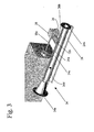
- a laser 14 produces a laser beam 16a, which is directed toward the core guidance tube 24 and focused by a laser beam delivery system 20 in the form of a translated laser beam 18b.
- the core guidance tube 24 includes a receiving end 24a, an expulsion end 24b, a middle section 24c, an interior 24d, a slot 26, and an access panel 28.
- the receiving end 24a is fluted or funnel-shaped to guide the core 12 into the middle section 24c (compare Figure 1 ).
- the slot 26, described in greater detail below, allows the laser beam 18b to circumferentially cut the core 12 to a desired length.
- the expulsion end 24b expulses a severed section of the core 12 after the translated laser beam 18b has made a cut C on the core 12 (see Figure 4 ). After discharge from the expulsion end 24b, the severed section of the core 12 is removed from the laser core cutting system 10 by known blowers, gravity, discharge conveyors and the like. An exemplary operation of the laser 14, the laser beam delivery system 20 and the core guidance tube 24 is described in greater detail below.
- the access panel 28 in this aspect of the invention is lingeably, swivably, removably, slidably, or otherwise attached to the core guidance tube 24.
- the access panel 28 permits an operator O to access the interior 24d of the core guidance tube 24 to clean the interior 24d, to remove a portion of the core 12, to perform maintenance on the core guidance tube 24, or to perform various other maintenance functions.
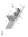
- the laser 14 and the laser beam delivery system 20 are shown with the core guidance tube 24 removed.
- the core 12 is shown being cut by the translated laser beam 18b as the core 12 rotates in a direction indicated by an arrow R.
- the laser beam 18b is shown cutting cleanly through a glued juncture J on the core 12.
- the laser beam delivery system 20 is mounted on a linear motor 22, which moves parallel to the machine direction and the continuous core 12.
- the linear motor 22 in this example moves the laser beam delivery system 20 away from and toward the laser 14.
- the linear motor 22 moves the laser beam delivery system 20 at a speed matching the translational speed of the core 12, which is continuously moving in the machine direction D. Therefore, as the core 12 rotates in the direction of arrow R, the core 12 is axially stationary relative to the laser beam 18b. Accordingly, the laser beam 18b makes the circumferential cut C in the core 12.
- Figure 5 shows a top plan view of the embodiment as shown in Figure 4 .
- the linear motor 22 is moving substantially parallel to the core 12 along the track assembly 30 in the machine direction indicated by arrow D.
- the laser beam 18a is translated by the laser beam delivery system 20 into the laser beam 18b (see Fig. 6 ) to make the cut C on the core 12.
- a selectable core penetration power of the translated laser beam 18b is shown that enables the laser beam 18b to cut the core 12.
- the laser will cut the core 12 circumferentially as described above but will not over-penetrate the core 12 beyond a far side 12a of the core 12.
- the laser 14 and the penetration power of its translated laser beam 18b are selected based on at least four criteria: 1) a rated power of the laser 14; 2) a basis weight of the windable material (e.g., webs W 1 , W 2 ) that forms the core 12; 3) the translational and rotational speeds of the windable material; and 4) the number of desired plies in the finished core 12.
- a continuous wave (CW), carbon dioxide (CO 2 ) laser having an average power of 500 watts (W) may be suitable for cutting the paperboard or cardboard that forms the core 12.
- An exemplary laser suitable for use as laser 14 is available from Coherent, Inc./DeMaria ElectroOptics Systems Inc. (DEOS), located in Bloomfield, Connecticut. Coherent/DEOS designs and manufactures the DIAMONDTM family of CO 2 lasers that are small enough to mount on a bench or a small machine but powerful enough to cut the windable materials that form the core 12.
- the DIAMONDTM laser family is maintenance free, completely sealed and requires no external gas, which makes it a highly reliable family of lasers.
- the DIAMONDTM laser family is available from 25 watts to 500 watts of average power (up to 3000 watts of peak power) with output wavelengths in the 10 and 9-micron regions.
- Q-switching allows the generation of laser pulses from about 1 to about 50 nanoseconds and from less than 1 megawatt (mW) to about 50 mW.
- Q-switching derives its name by switching a laser cavity quality factor, or Q factor, from a low to a high value suddenly; i.e., by releasing stored laser energy in a short, intense light pulse. Additional information on Q-switching can be found in Principles of Lasers, Third Edition, by Professor Orazio Svelto, available from Plenum Press, New York .
- the DIAMONDTM laser family provides a high intensity laser beam, which provides faster vaporization of non-metals such as cardboard and paperboard for the formation of the core 12.
- the high intensity beam of the DIAMONDSTM laser family produces a highly focused spot (0.075 millimeter (mm) diameter) that allows the 500-watt model generating 1500 peak power to produce instantaneous intensities of up to 0.3 mW/mm 2 at the core 12. This intensity is greater than many CW lasers of comparable power and provides for higher processing speeds of the laser 14.
- the DIAMONDTM laser family is provided by way of example only and is not intended to foreclose the use of other lasers as the laser 14.
- the CO 2 laser is an economical alternative, other gas lasers such Helium-Neon (He-Ne) or Argon (Ar) can be used.
- He-Ne Helium-Neon
- Ar Argon
- liquid lasers, chemical lasers, semiconductor lasers, solid-state lasers (e.g., ruby or alexandrite crystal), and other lasers having various power outputs can be used for the laser 14. More specifically, various lasers may be suitable depending on increases in the thickness of the windable material W 1 , W 2 ; the number of plies; and/or the translational and rotational speeds of the core 12.
- Nd:YAG solid-state laser
- the Nd:YAG is a Neodymium laser that utilizes an Nd 3+ ion as its active material in a laser medium of Y 2 Al 5 O 12 , or YAG, an acronym for yttrium aluminum garnet.
- the laser beam delivery system 20 is attached to the linear motor 22 in any suitable manner to hold the laser beam delivery system 20 relatively stationary as the linear motor 22 moves in the machine direction (see arrow D in Figure 5 ). As briefly introduced, the linear motor 22 moves the laser beam delivery system 20 substantially parallel to the continuous core 12.
- Any linear motion system capable of attaching, supporting and moving the laser beam delivery system 20 to traverse a length of the core guidance tube 24 can be used in place of the linear motor 22.
- a linear motion system include but are not limited to a servo-driven belt drive, an electromagnetic servo-drive, a cam shaft/follower system, a linear actuator, a ball-screw drive, a servo-pneumatic drive or any other form of locomotion that provides a repetitive straight line or back-and-forth motion.
- a Linear Servo MotorTM is available from Trilogy Systems located in Webster, Texas.
- the exemplary Linear Servo MotorTM is cost effective, simple in design and suitable as the linear motor 22 to accommodate the laser beam delivery system 20.
- the core 12 is continuously, rotatingly formed from the winding mandrel 16 as introduced above.
- the core 12 enters the core guidance tube 24 via the receiving end 24a, which in this example is funnel-shaped to more easily receive a first end (not shown) of the continuous core 12.
- the interior 24d of the core guidance tube 24 defines a complementary-sized inside diameter (I.D.).
- the continuous core 12 defines an outside diameter (O.D.) of approximately 1 inch (2.5 cm) to about 2 inches (5.1 cm), which is slightly smaller than the I.D of the core guidance tube 24.
- the core guidance tube 24 receives and guides the continuous core 12 in the machine direction (see Fig.
- the linear motion system is started, stopped and reversed by reaching a stop 34 and/or by receiving a control signal from a controller 36, such as a programmable logic computer, or from a proximity sensor 38 as seen in Figure 4 .
- a controller 36 such as a programmable logic computer
- a proximity sensor 38 as seen in Figure 4 .
- the stop 34, controller 36, and/or the proximity sensor 38 are not required if, for instance, the linear motor 22 is utilized since the linear motor 22 is self-contained.
- the linear motor 22 is designed to move a required distance to achieve the circumferential cut C on the core 12 and then reverse direction.
- the length of the slot 26 is at least equal to the required distance.
- the linear motor 22 moves at the tanslational speed to match the translational speed of the core 12, the laser 14 lases for a period of time sufficient to complete the cut C about the circumference of the core 1.2. Stated another way, the laser 14 moves the required distance, which is at least equivalent to a ratio of the translational speed of the linear motor 22 and the core 12 divided by the rotational speed of the core 12 multiplied by the circumference of the core 12.
- the linear motor 22 communicates with the laser 12 to deactivate the laser beam 18a once the linear motor 22 traverses the required distance, such as the length of the slot 26.
- the laser 14 may be designed in electronic communication with the controller 36 or proximity sensor 38 to deactivate the laser beam 18b and/or to reverse a movement of the laser beam delivery system 20.
- the proximity sensor 38 senses the stop 34 and communicates with the controller 36 to reverse a movement of the alternative linear motion system in a direction opposite the arrow D.
- the controller 36 is programmed to deactivate the laser beam 18b after a preprogrammed distance.
- the linear motor 22 permits the laser beam delivery system 20 to match the translational speed of the core 12 moving in the machine direction (arrow D).
- the laser beam delivery system 20 is thus axially stationary to a point on the core 12.
- the axially stationary core 12 is also continuously rotating thus presenting the rotating circumferential surface to the translated laser beam 18b.
- the laser beam 18b lases the circumferential surface of the core 12 to make the cut C from the first end 26a to the after end 26b of the slot 26. Once the laser beam 18b reaches the after end 26b, the cut C is complete since the cut C is a function of the length of the slot 26.
- a method for cutting a rolled product core includes the steps of:
- the laser beam delivery system 20 includes a reflector, a mirror, or other optical system (not shown) to redirect or translate the laser beam 18a in the form of laser beam 18b.
- Laser beam 18b is directed toward the core guidance tube 24 to crosscut the core 12 similar to the foregoing embodiment.
- the method may also include the sub-steps of deactivating the laser beam 18b at a sensed or pre-programmed point.
- the controller 36 or proximity sensor 38 similar to those described in the previous embodiment are provided to sense this point and to communicate the point to the laser 14 if another linear motion system is utilized other than the linear motor 22.
- the method may further include the steps of discharging a section of the core 12 after it has been cut by the laser beam 18b from the expulsion end 24b of the core guidance tube 24.
- the discharged section of the core 12 can be removed from the core guidance tube 24 by a blower or air blast (not shown), a force of gravity, and/or a discharge conveyor (not shown) to send the discharged section of the core 12 upstream to wind up a rolled web product or to be used as a container or as a base structure for another product.
Landscapes
- Physics & Mathematics (AREA)
- Optics & Photonics (AREA)
- Engineering & Computer Science (AREA)
- Plasma & Fusion (AREA)
- Mechanical Engineering (AREA)
- Laser Beam Processing (AREA)
- Auxiliary Devices For And Details Of Packaging Control (AREA)
Applications Claiming Priority (3)
| Application Number | Priority Date | Filing Date | Title |
|---|---|---|---|
| US10/325,685 US6861615B2 (en) | 2002-12-20 | 2002-12-20 | Method and system for cutting cores with a laser |
| US325685 | 2002-12-20 | ||
| PCT/US2003/029004 WO2004060601A1 (en) | 2002-12-20 | 2003-09-12 | Method and system for cutting cores with a laser |
Publications (2)
| Publication Number | Publication Date |
|---|---|
| EP1578555A1 EP1578555A1 (en) | 2005-09-28 |
| EP1578555B1 true EP1578555B1 (en) | 2009-11-11 |
Family
ID=32593853
Family Applications (1)
| Application Number | Title | Priority Date | Filing Date |
|---|---|---|---|
| EP03754609A Expired - Lifetime EP1578555B1 (en) | 2002-12-20 | 2003-09-12 | Method and system for cutting cores with a laser |
Country Status (6)
| Country | Link |
|---|---|
| US (1) | US6861615B2 (pt) |
| EP (1) | EP1578555B1 (pt) |
| AU (1) | AU2003272429A1 (pt) |
| BR (1) | BRPI0317062B1 (pt) |
| DE (1) | DE60330049D1 (pt) |
| WO (1) | WO2004060601A1 (pt) |
Families Citing this family (17)
| Publication number | Priority date | Publication date | Assignee | Title |
|---|---|---|---|---|
| DE10066062A1 (de) * | 2000-08-04 | 2004-05-27 | Sca Hygiene Products Gmbh | Vorrichtung zum Trennen und/oder Perforieren |
| US20040086698A1 (en) * | 2002-10-31 | 2004-05-06 | Collins Robert H. | Method and apparatus for the application and control of a continuous or intermittent tail seal |
| US20060097430A1 (en) * | 2004-11-05 | 2006-05-11 | Li Xiaochun | UV pulsed laser machining apparatus and method |
| US8211078B2 (en) | 2005-02-17 | 2012-07-03 | The Procter And Gamble Company | Sanitary napkins capable of taking complex three-dimensional shape in use |
| US9579238B2 (en) | 2005-02-17 | 2017-02-28 | The Procter & Gamble Company | Sanitary napkins capable of taking complex three-dimensional shape in use |
| US20070014948A1 (en) * | 2005-07-13 | 2007-01-18 | Sonoco Development, Inc. | Laser-cleanable winding cores and cleaning method therefor |
| US9034007B2 (en) * | 2007-09-21 | 2015-05-19 | Insera Therapeutics, Inc. | Distal embolic protection devices with a variable thickness microguidewire and methods for their use |
| ITBO20100087A1 (it) * | 2010-02-18 | 2011-08-19 | Emmeci Spa | Apparato per il taglio di elementi tubolari in materiale cartaceo con unita' laser. |
| ITBO20110334A1 (it) * | 2011-06-08 | 2012-12-09 | Barbalab S R L | Macchina per il taglio di tubi |
| CN103231174B (zh) * | 2012-12-27 | 2015-04-22 | 苏州领创激光科技有限公司 | 圆管形态跟踪式激光切割机 |
| US8715314B1 (en) | 2013-03-15 | 2014-05-06 | Insera Therapeutics, Inc. | Vascular treatment measurement methods |
| US8690907B1 (en) | 2013-03-15 | 2014-04-08 | Insera Therapeutics, Inc. | Vascular treatment methods |
| CA2901443A1 (en) | 2013-03-15 | 2014-09-25 | Insera Therapeutics, Inc. | Vascular treatment devices and methods |
| US8679150B1 (en) | 2013-03-15 | 2014-03-25 | Insera Therapeutics, Inc. | Shape-set textile structure based mechanical thrombectomy methods |
| EP3416568A4 (en) | 2016-02-16 | 2019-10-16 | Insera Therapeutics, Inc. | SUCTION DEVICES AND ANCHORED FLOW REVERSING DEVICES |
| US10806635B2 (en) | 2016-03-15 | 2020-10-20 | The Procter & Gamble Company | Methods and apparatuses for separating and positioning discrete articles |
| CN109227744B (zh) * | 2018-10-09 | 2020-11-17 | 日照盛恒环保科技有限公司 | 一种塑料件用打孔装置 |
Family Cites Families (25)
| Publication number | Priority date | Publication date | Assignee | Title |
|---|---|---|---|---|
| US2769600A (en) | 1952-07-16 | 1956-11-06 | Paper Converting Machine Co | Web winding machine |
| GB1040768A (en) | 1963-10-22 | 1966-09-01 | Head Wrightson & Co Ltd | Method and apparatus for cutting metal sheet, tubes, bars, strip and the like by laser devices |
| DE2350933C3 (de) | 1973-10-10 | 1981-10-29 | Winkler & Dünnebier, Maschinenfabrik und Eisengießerei GmbH & Co KG, 5450 Neuwied | Vorrichtung zum Formbrennschneiden einer bewegten Materialbahn mittels eines Laserstrahles |
| US4049945A (en) | 1973-10-10 | 1977-09-20 | Winkler & Dunnebier Maschinenfabrik Und Eisengiesserei Kg | Method of and apparatus for cutting material to shape from a moving web by burning |
| US4317021A (en) * | 1980-02-22 | 1982-02-23 | The United States Of America As Represented By The United States Department Of Energy | Laser cutting apparatus for nuclear core fuel subassembly |
| US4430548A (en) | 1982-04-26 | 1984-02-07 | Macken John A | Laser apparatus and process for cutting paper |
| JPS59194967A (ja) | 1983-04-19 | 1984-11-05 | Fuji Xerox Co Ltd | 複写機等のロ−ル紙切断装置 |
| JPS59194966A (ja) | 1983-04-19 | 1984-11-05 | Fuji Xerox Co Ltd | 複写機等のロ−ル紙切断装置 |
| DE3447405A1 (de) | 1984-12-24 | 1986-07-03 | Winkler & Dünnebier, Maschinenfabrik und Eisengießerei GmbH & Co KG, 5450 Neuwied | Vorrichtung zum formbrennschneiden einer bewegten materialbahn mittels eines laserstrahls |
| US4636608A (en) * | 1985-11-15 | 1987-01-13 | Benteler Corporation | Laser contour cut door beams |
| JPS6363591A (ja) | 1986-09-02 | 1988-03-19 | Mitsubishi Electric Corp | レ−ザ裁断装置 |
| JPS63307030A (ja) | 1987-06-09 | 1988-12-14 | Tsubakimoto Chain Co | 巻取紙外装紙の解悃装置 |
| US5213649A (en) | 1990-10-15 | 1993-05-25 | Beloit Technologies, Inc. | Apparatus for receiving and cutting a continuous web |
| NL9100942A (nl) | 1991-05-31 | 1992-12-16 | Drent H H Maschf Bv | Werkwijze en inrichting voor het doorsnijden dan wel perforeren van een bewegende papierbaan. |
| JPH05123880A (ja) | 1991-11-01 | 1993-05-21 | Toyota Motor Corp | レーザ切断方法 |
| DE4209630A1 (de) | 1992-03-25 | 1993-09-30 | Basf Ag | Verfahren und Vorrichtung zum Trennen einer Warenbahn |
| DE4219431C2 (de) * | 1992-06-13 | 1994-08-04 | Albert Seufert | Vorrichtung zum maschinellen Ausklinken von Rohren |
| JPH06206651A (ja) | 1993-01-11 | 1994-07-26 | Fuji Photo Film Co Ltd | ウェブ切断巻付方法および装置 |
| US5767481A (en) | 1995-09-18 | 1998-06-16 | Voith Sulzer Paper Technology North America, Inc. | Laser tail cutter assembly |
| JP3774254B2 (ja) | 1995-09-30 | 2006-05-10 | トッパン・フォームズ株式会社 | 連続用紙の切断加工装置 |
| US5994667A (en) * | 1997-10-15 | 1999-11-30 | Scimed Life Systems, Inc. | Method and apparatus for laser cutting hollow workpieces |
| US6191382B1 (en) | 1998-04-02 | 2001-02-20 | Avery Dennison Corporation | Dynamic laser cutting apparatus |
| JP3071758B2 (ja) * | 1998-05-20 | 2000-07-31 | ヤマザキマザック株式会社 | 3次元レーザ加工機及び3次元レーザ加工機における加工プログラムの作成制御方法 |
| JP2000143046A (ja) | 1998-11-17 | 2000-05-23 | Dainippon Printing Co Ltd | 巻取仕立て装置 |
| US6335508B1 (en) * | 2000-05-25 | 2002-01-01 | Kyong H. Nam | Pipe handling system for laser and other pipe treating processes |
-
2002
- 2002-12-20 US US10/325,685 patent/US6861615B2/en not_active Expired - Lifetime
-
2003
- 2003-09-12 WO PCT/US2003/029004 patent/WO2004060601A1/en not_active Ceased
- 2003-09-12 EP EP03754609A patent/EP1578555B1/en not_active Expired - Lifetime
- 2003-09-12 AU AU2003272429A patent/AU2003272429A1/en not_active Abandoned
- 2003-09-12 BR BRPI0317062-4A patent/BRPI0317062B1/pt not_active IP Right Cessation
- 2003-09-12 DE DE60330049T patent/DE60330049D1/de not_active Expired - Lifetime
Also Published As
| Publication number | Publication date |
|---|---|
| BRPI0317062B1 (pt) | 2015-07-28 |
| WO2004060601A1 (en) | 2004-07-22 |
| US6861615B2 (en) | 2005-03-01 |
| AU2003272429A1 (en) | 2004-07-29 |
| DE60330049D1 (de) | 2009-12-24 |
| EP1578555A1 (en) | 2005-09-28 |
| US20040118820A1 (en) | 2004-06-24 |
| BR0317062A (pt) | 2005-10-25 |
Similar Documents
| Publication | Publication Date | Title |
|---|---|---|
| EP1578555B1 (en) | Method and system for cutting cores with a laser | |
| EP0553232B1 (en) | Method for effecting a set change in a winder | |
| EP0553275B1 (en) | Web cutting apparatus and method | |
| EP2546052B1 (en) | A machine and a method for producing packaging boxes | |
| KR100307429B1 (ko) | 테일실러를내장한권취기 | |
| JP5980750B2 (ja) | ラベル用紙の加工装置 | |
| KR101115813B1 (ko) | 릴교체의 단계에 있어서 풀린 재료에 대한 일시적 축적부재를 가진 웹형상 재료의 릴용 언와인더 장치와 그 관련방법 | |
| EP0507747B1 (en) | Perforating apparatus for paper webs and the like, with reciprocating motion of translation of the counterblade | |
| JP2005532238A (ja) | 種々の大きさのペーパーロールを製造する巻返し機及び方法 | |
| US7887003B2 (en) | Machine and method for the production of rolls of weblike material together with a winding core and roll thus obtained | |
| WO1992006913A1 (en) | Apparatus and method for winding a continuous traveling web on a new core | |
| US9221229B2 (en) | Apparatus and method for producing tubular sections for manufacturing bags | |
| TWI501829B (zh) | 雷射切割裝置、及具備該雷射切割裝置之切條機、及雷射切割方法 | |
| US5901917A (en) | Air-powered web slasher | |
| CA2328611C (en) | Method and device for cutting sheets comprised of a carrier film and a decorative layer located thereon, especially embossed sheets | |
| KR20090046986A (ko) | 포장재용 필름원단 가공장치 | |
| CA2265087A1 (en) | Method for cutting a leader and a tail in a web in a papermaking machine | |
| US5720446A (en) | Method and device for cutting photographic products into strips | |
| KR100351587B1 (ko) | 롤원단 가공 시스템의 절단/접착 유니트 | |
| FI95612C (fi) | Paperiradan leikkauslaite ja menetelmä paperiradan leikkauksessa | |
| JP2520838B2 (ja) | 芯なしトイレットペ―パ―ロ―ル製造機 | |
| JPH05147786A (ja) | 枠替方法 | |
| JPH04169455A (ja) | 枠替方法 | |
| JPS60121090A (ja) | フィルムの切断方法 | |
| JP2002167088A (ja) | ウェブ切断方法及びウェブロール切替方法 |
Legal Events
| Date | Code | Title | Description |
|---|---|---|---|
| PUAI | Public reference made under article 153(3) epc to a published international application that has entered the european phase |
Free format text: ORIGINAL CODE: 0009012 |
|
| 17P | Request for examination filed |
Effective date: 20050706 |
|
| AK | Designated contracting states |
Kind code of ref document: A1 Designated state(s): AT BE BG CH CY CZ DE DK EE ES FI FR GB GR HU IE IT LI LU MC NL PT RO SE SI SK TR |
|
| AX | Request for extension of the european patent |
Extension state: AL LT LV MK |
|
| DAX | Request for extension of the european patent (deleted) | ||
| RBV | Designated contracting states (corrected) |
Designated state(s): DE FR IT |
|
| RIN1 | Information on inventor provided before grant (corrected) |
Inventor name: HARRIS, NATHAN, C. Inventor name: WOJCIK, STEVEN, J. |
|
| 17Q | First examination report despatched |
Effective date: 20080502 |
|
| GRAP | Despatch of communication of intention to grant a patent |
Free format text: ORIGINAL CODE: EPIDOSNIGR1 |
|
| GRAS | Grant fee paid |
Free format text: ORIGINAL CODE: EPIDOSNIGR3 |
|
| GRAA | (expected) grant |
Free format text: ORIGINAL CODE: 0009210 |
|
| AK | Designated contracting states |
Kind code of ref document: B1 Designated state(s): DE FR IT |
|
| REF | Corresponds to: |
Ref document number: 60330049 Country of ref document: DE Date of ref document: 20091224 Kind code of ref document: P |
|
| PLBE | No opposition filed within time limit |
Free format text: ORIGINAL CODE: 0009261 |
|
| STAA | Information on the status of an ep patent application or granted ep patent |
Free format text: STATUS: NO OPPOSITION FILED WITHIN TIME LIMIT |
|
| 26N | No opposition filed |
Effective date: 20100812 |
|
| PGFP | Annual fee paid to national office [announced via postgrant information from national office to epo] |
Ref country code: FR Payment date: 20121001 Year of fee payment: 10 |
|
| PGFP | Annual fee paid to national office [announced via postgrant information from national office to epo] |
Ref country code: DE Payment date: 20120927 Year of fee payment: 10 |
|
| REG | Reference to a national code |
Ref country code: FR Ref legal event code: ST Effective date: 20140530 |
|
| REG | Reference to a national code |
Ref country code: DE Ref legal event code: R119 Ref document number: 60330049 Country of ref document: DE Effective date: 20140401 |
|
| PG25 | Lapsed in a contracting state [announced via postgrant information from national office to epo] |
Ref country code: DE Free format text: LAPSE BECAUSE OF NON-PAYMENT OF DUE FEES Effective date: 20140401 Ref country code: FR Free format text: LAPSE BECAUSE OF NON-PAYMENT OF DUE FEES Effective date: 20130930 |
|
| PGFP | Annual fee paid to national office [announced via postgrant information from national office to epo] |
Ref country code: IT Payment date: 20220926 Year of fee payment: 20 |
|
| P01 | Opt-out of the competence of the unified patent court (upc) registered |
Effective date: 20230511 |