EP1577910B1 - Hauptleiter für eine kapazitiv gesteuerte hochspannungswicklung - Google Patents
Hauptleiter für eine kapazitiv gesteuerte hochspannungswicklung Download PDFInfo
- Publication number
- EP1577910B1 EP1577910B1 EP05290370A EP05290370A EP1577910B1 EP 1577910 B1 EP1577910 B1 EP 1577910B1 EP 05290370 A EP05290370 A EP 05290370A EP 05290370 A EP05290370 A EP 05290370A EP 1577910 B1 EP1577910 B1 EP 1577910B1
- Authority
- EP
- European Patent Office
- Prior art keywords
- conductor
- conductors
- main conductor
- control
- transposed
- Prior art date
- Legal status (The legal status is an assumption and is not a legal conclusion. Google has not performed a legal analysis and makes no representation as to the accuracy of the status listed.)
- Expired - Lifetime
Links
- 239000004020 conductor Substances 0.000 title claims abstract description 106
- 238000004804 winding Methods 0.000 title claims abstract description 14
- RYGMFSIKBFXOCR-UHFFFAOYSA-N Copper Chemical compound [Cu] RYGMFSIKBFXOCR-UHFFFAOYSA-N 0.000 claims abstract 5
- 229910052802 copper Inorganic materials 0.000 claims abstract 5
- 239000010949 copper Substances 0.000 claims abstract 5
- 238000004519 manufacturing process Methods 0.000 claims description 8
- 238000003490 calendering Methods 0.000 claims description 4
- 235000012771 pancakes Nutrition 0.000 claims 3
- 238000000034 method Methods 0.000 description 3
- 229910000679 solder Inorganic materials 0.000 description 2
- 239000000853 adhesive Substances 0.000 description 1
- 238000004026 adhesive bonding Methods 0.000 description 1
- 230000001070 adhesive effect Effects 0.000 description 1
- 238000010276 construction Methods 0.000 description 1
- 239000011810 insulating material Substances 0.000 description 1
- 238000009413 insulation Methods 0.000 description 1
- 238000002955 isolation Methods 0.000 description 1
- 238000000926 separation method Methods 0.000 description 1
- 238000005476 soldering Methods 0.000 description 1
Images
Classifications
-
- H—ELECTRICITY
- H01—ELECTRIC ELEMENTS
- H01F—MAGNETS; INDUCTANCES; TRANSFORMERS; SELECTION OF MATERIALS FOR THEIR MAGNETIC PROPERTIES
- H01F27/00—Details of transformers or inductances, in general
- H01F27/34—Special means for preventing or reducing unwanted electric or magnetic effects, e.g. no-load losses, reactive currents, harmonics, oscillations, leakage fields
- H01F27/343—Preventing or reducing surge voltages; oscillations
- H01F27/345—Preventing or reducing surge voltages; oscillations using auxiliary conductors
-
- H—ELECTRICITY
- H01—ELECTRIC ELEMENTS
- H01F—MAGNETS; INDUCTANCES; TRANSFORMERS; SELECTION OF MATERIALS FOR THEIR MAGNETIC PROPERTIES
- H01F27/00—Details of transformers or inductances, in general
- H01F27/28—Coils; Windings; Conductive connections
- H01F27/2871—Pancake coils
-
- H—ELECTRICITY
- H01—ELECTRIC ELEMENTS
- H01F—MAGNETS; INDUCTANCES; TRANSFORMERS; SELECTION OF MATERIALS FOR THEIR MAGNETIC PROPERTIES
- H01F27/00—Details of transformers or inductances, in general
- H01F27/28—Coils; Windings; Conductive connections
- H01F27/2823—Wires
- H01F2027/2838—Wires using transposed wires
Definitions
- the invention relates to a main conductor for a capacitively controlled high-voltage winding according to the preamble of claims 1 and 2 and to a method for producing a main conductor for a capacitively controlled high-voltage winding according to the preamble of patent claim 5.
- control conductor is arranged spatially within the main conductor and galvanically isolated from the main conductor.
- the control conductor is arranged between two stacks of flat superposed individual conductors forming the main conductor.
- the control conductor either insulation or the room between control conductor and main conductor is filled by a padding or by an intermediate layer of insulating material.
- the present invention has for its object to provide the main conductor according to the preamble of claims 1 and 2 with an alternative construction of the control conductor and at the same time to improve its stability and to provide a corresponding method for its production.
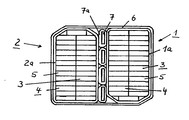
- the sole figure of the drawing shows a main conductor for a capacitive controlled high-voltage winding which is composed of two twisted conductors 1 and 2.
- Each twisting conductor has a multiplicity of rectangular partial conductors 5 located in two juxtaposed stacks 3, 4.
- the top and bottom ladder 5 change from the adjacent stacks 3 and 4 into the other stacks 3 and 4, the ladder 5 preferably being offset by a half step length in each case. In this case, a constant total height is achieved at odd-numbered Drilleitern.
- Each twisting conductor 1 and 2 has an insulating sheath 1 a and 2 a, which is preferably a wrapping made of paper. Between the Drilleitern 1 and 2 a plurality of flat copper-made control conductor 7 are arranged, which each have an insulating sleeve 7a made of paper.
- control conductors 7 are connected in a first embodiment of the main conductor with one of the twisting conductor 1 or 2, wherein the connection is made either by selective or full-surface bonding with a curable adhesive.
- the two together with the control conductor 7 the main conductor forming conductor 1 and 2 are surrounded in a second embodiment of a sheath 6 made of creped paper.
- a sheath 6 made of creped paper.
- a creped paper micro-creped and calendered insulating paper is used for strength reasons.
- the two twisted conductors 1 and 2 are provided.
- the twisted conductors 1 and 2 are brought together and the control conductors 7 are arranged between the twisted conductors 1 and 2 and both twisted conductors 1 and 2 are wrapped with one or more layers 6 of paper.
- 6 micro-creped and calendered paper is used for the wrapping.
- the control conductors 7 can be attached by gluing before or during the merging of the twisting conductors 1 and 2 on one of the twisting conductors 1, 2.
Landscapes
- Engineering & Computer Science (AREA)
- Power Engineering (AREA)
- Coils Of Transformers For General Uses (AREA)
- Insulating Of Coils (AREA)
- Coil Winding Methods And Apparatuses (AREA)
- Fixed Capacitors And Capacitor Manufacturing Machines (AREA)
Description
- Die Erfindung betrifft einen Hauptleiter für eine kapazitiv gesteuerte Hochspannungswicklung nach dem Oberbegriff der Patentansprüche 1 und 2 sowie ein Verfahren zur Herstellung eines Hauptleiters für eine kapazitiv gesteuerte Hochspannungswicklung nach dem Oberbegriff des Patentanspruchs 5.
- Aus der
DE 199 26 540 C1 ist eine Hochspannungswicklung bekannt, bei welcher die Spulenwicklungen aus sogenannten Drilleitern hergestellt sind. Durch die Verwendung von Drilleitern werden die durch das Streufeld verursachten Zusatzverluste verringert. Darüberhinaus kann der zur Verfügung stehende Wickelraum durch einen höheren Füllfaktor besser ausgenutzt werden. - Die Herstellung ineinander gewickelter Spulen erfordert in jedem Fall Lötverbindungen, die bei der Verwendung von Drilleitern nur unter größeren Schwierigkeiten oder überhaupt nicht realisierbar sind. Bei der Verwendung von Drilleitern ist daher zur Vermeidung von Lötverbindungen eine fortlaufend wickelbare Doppelspulenschaltung anzustreben, in der die kapazitive Steuerung durch einen besonderen Steuerleiter erreichbar ist, dessen Lötverbindungen einfach und wirtschaftlich herstellbar sind.
- Bei der
DE 199 26 540 C1 ist der Steuerleiter räumlich innerhalb des Hauptleiters angeordnet und von dem Hauptleiter galvanisch getrennt. Der Steuerleiter ist zwischen zwei Stapeln von flach aufeinander liegenden, gemeinsam den Hauptleiter bildenden Einzelleitern angeordnet. Zur galvanischen Trennung des Steuerleiters von dem Hauptleiter weist der Steuerleiter entweder eine Isolierung auf oder der Raum zwischen Steuerleiter und Hauptleiter ist durch eine Auffüllung oder durch eine Zwischenlage aus Isolierwerkstoff ausgefüllt. - Durch die Anordnung des Steuerleiters zwischen den beiden Teilleiterstapeln besteht die Gefahr, daß der Steuerleiter während der Weiterverarbeitung des Drilleiters z. B. bei der Herstellung einer Transformatorenwicklung verschoben wird und dadurch die Isolierung des Steuerleiters oder der Teilleiter des Drilleiters zerstört werden kann. Bei der Herstellung der Wicklung besteht darüberhinaus die Gefahr, daß die erforderliche geometrisch korrekte Anordnung der einzelnen Lagen einer Wicklung nicht mehr gewährleistet ist.
- Aus der
US 6 271 743 B1 , welche als nächstliegender Stand der Technik angesehen wird, geht ein Verfahren zur Herstellung eines Hauptleiters für eine kapazitiv gesteuerte Hochspannungswicklung aus Scheibenspulen für Transformatoren hervor, bei dem zunächst ein erster und ein zweiter Drilleiter bereitgestellt werden. Danach werden die beiden Drilleiter zusammengeführt und zwischen denselben wird ein Steuerleiter angeordnet. Um die beiden Drilleiter wird zusammen mit dem zwischen ihnen befindlichen Steuerleiter eine isolierende Hülle herumgeformt, die dem Zusammenhalt der einzelnen Teile des Hauptleiters dient. - Der vorliegenden Erfindung liegt die Aufgabe zugrunde, den Hauptleiter gemäß dem Oberbegriff der Patentansprüche 1 und 2 mit einem alternativen Aufbau des Steuerleiters bereitzustellen und gleichzeitig seine Stabilität zu verbessern sowie ein entsprechendes Verfahren zu seiner Herstellung anzugeben.
- Diese Aufgabe wird entsprechend den kennzeichnenden Merkmalen der Patentansprüche 1, 2 und 5 gelöst.
- Durch die Verwendung von zwei Drilleitern und die Anordnung des Steuerleiters zwischen den Drilleitern ist gewährleistet, daß beim üblichen Röbelprozeß keinerlei Veränderungen vorgenommen werden müssen. Die Fixierung des Steuerleiters innerhalb des Hauptleiters zwischen den beiden Drilleitern stellt sicher, daß der Steuerleiter sich nicht mehr verschieben kann.
- Die Erfindung ist anhand des in der Zeichnung schematisch dargestellten Ausführungsbeispiels näher erläutert.
- Die einzige Figur der Zeichnung zeigt einen Hauptleiter für eine kapazitiv gesteuerte Hochspannungswicklung der aus zwei Drilleitern 1 und 2 aufgebaut ist. Jeder Drilleiter weist eine Vielzahl von in zwei nebeneinander angeordneten Stapeln 3, 4 befindlichen rechteckförmigen Teilleitern 5 auf. Bei der Herstellung der Drilleiter 1 und 2 wechselt aus den nebeneinander liegenden Stapeln 3 und 4 jeweils der oberste und unterste Leiter 5 in den anderen Stapel 3 und 4 über, wobei die Leiter 5 vorzugsweise um jeweils eine halbe Schrittlänge versetzt werden. Dabei wird bei ungeradzahligen Drilleitern eine gleichbleibende Gesamthöhe erreicht.
- Jeder Drilleiter 1 und 2 weist eine Isolierhülle 1 a und 2a auf, die vorzugsweise eine Umhüllung aus Papier ist. Zwischen den Drilleitern 1 und 2 sind mehrere aus Flachkupfer hergestellte Steuerleiter 7 angeordnet, die jeder für sich eine Isolierhülle 7a aus Papier aufweisen.
- Die Steuerleiter 7 sind in einer ersten Ausführungsform des Hauptleiters mit einem der Drilleiter 1 oder 2 verbunden, wobei die Verbindung entweder durch punktuelles oder vollflächiges Verkleben mit einem aushärtbaren Kleber erfolgt.
- Die beiden zusammen mit dem Steuerleiter 7 den Hauptleiter bildenden Drilleiter 1 und 2 sind in einer zweiten Ausführungsform von einer Hülle 6 aus gekrepptem Papier umgeben. Als gekrepptes Papier wird aus Gründen der Festigkeit mikrogekrepptes und kalandriertes Isolierpapier eingesetzt.
- Zur Herstellung des in der Zeichnung dargestellten Hauptleiters werden zunächst die beiden Drilleiter 1 und 2 bereitgestellt. In einem nächsten Arbeitsschritt werden die Drilleiter 1 und 2 zusammengeführt und die Steuerleiter 7 zwischen den Drilleitern 1 und 2 angeordnet und beide Drilleiter 1 und 2 mit einer oder mehreren Lagen 6 aus Papier umwickelt. Aus Gründen der Festigkeit wird für die Umwicklung 6 mikrogekrepptes und kalandriertes Papier verwendet. Die Steuerleiter 7 können vor oder beim Zusammenführen der Drilleiter 1 und 2 an einem der Drilleiter 1, 2 durch Kleben befestigt werden.
Claims (5)
- Hauptleiter für eine kapazitiv gesteuerte Hochspannungswicklung aus Scheibenspulen für Transformatoren, wobei der Hauptleiter für den Laststrom aus zwei galvanisch getrennt voneinander angeordneten Drilleitern (1,2) besteht, und ein räumlich dazu angeordneter Steuerleiter innerhalb des Hauptleiters und galvanisch getrennt vom Hauptleiter vorgesehen ist, dadurch gekennzeichnet, daß der Steuerleiter (7) aus mehreren flachen, mit einer Isolierhülle (7a) versehenen Kupferleitern besteht und daß der Steuerleiter (7) an einem der Drilleiter (1,2) befestigt ist.
- Hauptleiter für eine kapazitiv gesteuerte Hochspannungswicklung aus Scheibenspulen für Transformatoren, wobei der Hauptleiter aus zwei galvanisch getrennt voneinander angeordneten Drilleitern (1,2) besteht, und ein räumlich dazu angeordneter Steuerleiter innerhalb des Hauptleiters und galvanisch getrennt vom Hauptleiter vorgesehen ist, dadurch gekennzeichnet, daß der Steuerleiter (7) aus mehreren flachen, mit einer Isolierhülle (7a) versehenen Kupferleitern besteht und daß der aus den beiden Drilleitern (1,2) und dem Steuerleiter (7) bestehende Hauptleiter von einer Hülle (6) aus mikrogekrepptem und kalandriertem Isolierpapierumgeben ist.
- Hauptleiter nach Anspruch 1, dadurch gekennzeichnet, daß der Steuerleiter (7) mit der Seitenfläche eines der Drilleiter (1,2) verklebt ist.
- Hauptleiter nach einem der Ansprüche 1 bis 3, dadurch gekennzeichnet, daß die Isolierhülle (7a) der Kupferleiter aus Papier besteht.
- Verfahren zur Herstellung eines Hauptleiters für eine kapazitiv gesteuerte Hochspannungswicklung aus Scheibenspulen für Transformatoren gemäß Anspruch 1 oder Anspruch 2, wobei der Hauptleiter für den Laststrom aus zwei galvanisch getrennt voneinander angeordneten Drilleitern (1,2) aufgebaut wird, und ein räumlich dazu angeordneter Steuerleiter innerhalb des Hauptleiters und galvanisch getrennt von demselben angebracht wird, und wobei zunächst ein erster und ein zweiter Drilleiter (1,2) bereitgestellt werden, danach die beiden Drilleiter (1,2) zusammengeführt werden und zwischen denselben ein Steuerleiter (7) angeordnet wird und beide Drilleiter (1,2) zusammen mit dem zwischen ihnen befindlichen Steuerleiter (7) von einer isolierenden Hülle umgeben werden, welche dem Zusammenhalt der einzelnen Teile dient, dadurch gekennzeichnet, daß ein aus mehreren flachen, mit einer Isolierhülle (7a) versehenen Kupferleitern bestehender Steuerleiter (7) verwendet wird, der entweder an einem der Drilleiter (1,2) befestigt wird oder zusammen mit den beiden Drilleitern(1,2) mit einer Hülle (6) aus mikrogekrepptem und kalandriertem Isolierpapier umgeben wird.
Applications Claiming Priority (2)
| Application Number | Priority Date | Filing Date | Title |
|---|---|---|---|
| DE102004013416 | 2004-03-18 | ||
| DE102004013416A DE102004013416A1 (de) | 2004-03-18 | 2004-03-18 | Hauptleiter für eine kapazitiv gesteuerte Hochspannungswicklung |
Publications (3)
| Publication Number | Publication Date |
|---|---|
| EP1577910A2 EP1577910A2 (de) | 2005-09-21 |
| EP1577910A3 EP1577910A3 (de) | 2007-05-02 |
| EP1577910B1 true EP1577910B1 (de) | 2008-09-03 |
Family
ID=34833189
Family Applications (1)
| Application Number | Title | Priority Date | Filing Date |
|---|---|---|---|
| EP05290370A Expired - Lifetime EP1577910B1 (de) | 2004-03-18 | 2005-02-17 | Hauptleiter für eine kapazitiv gesteuerte hochspannungswicklung |
Country Status (7)
| Country | Link |
|---|---|
| US (1) | US7098764B2 (de) |
| EP (1) | EP1577910B1 (de) |
| CN (1) | CN100587862C (de) |
| AT (1) | ATE407437T1 (de) |
| CA (1) | CA2500568C (de) |
| DE (2) | DE102004013416A1 (de) |
| ES (1) | ES2314590T3 (de) |
Families Citing this family (6)
| Publication number | Priority date | Publication date | Assignee | Title |
|---|---|---|---|---|
| UA87897C2 (ru) * | 2007-09-24 | 2009-08-25 | Роман Петрович Долюк | Трансформатор высокого напряжения и большой мощности с распределительным экраном долюка |
| US8991709B2 (en) | 2010-08-30 | 2015-03-31 | Tagstar Systems Gmbh | Tamper-proof RFID label |
| US9897154B2 (en) | 2011-03-31 | 2018-02-20 | Gunite Corporation | Disk brake hub assembly |
| US9566957B2 (en) | 2011-03-31 | 2017-02-14 | Gunite Corporation | Disk brake hub assembly |
| US8950556B2 (en) | 2011-03-31 | 2015-02-10 | Gunite Corporation | Disk brake hub assembly |
| JP2016167528A (ja) * | 2015-03-10 | 2016-09-15 | 株式会社日立製作所 | 静止誘導電器及びその製造方法 |
Citations (1)
| Publication number | Priority date | Publication date | Assignee | Title |
|---|---|---|---|---|
| US3260778A (en) * | 1964-01-23 | 1966-07-12 | Richard R Walton | Treatment of materials |
Family Cites Families (9)
| Publication number | Priority date | Publication date | Assignee | Title |
|---|---|---|---|---|
| GB1158325A (en) * | 1965-11-09 | 1969-07-16 | English Electric Co Ltd | Improvements in or relating to Windings for Inductive Apparatus. |
| DE2323304C3 (de) * | 1973-05-09 | 1978-09-07 | Transformatoren Union Ag, 7000 Stuttgart | Stufenwicklung für Transformatoren |
| DE2418230C3 (de) * | 1974-04-13 | 1979-09-13 | Transformatoren Union Ag, 7000 Stuttgart | Kapazitiv gesteuerte Hochspannungswicklung aus Scheibenspulen für Transformatoren mit großen Leistungen |
| US4797509A (en) * | 1987-11-19 | 1989-01-10 | Nicor, Inc. | Method and apparatus for connecting electrical conductors together |
| US5209973A (en) * | 1988-10-19 | 1993-05-11 | Beiersdorf Aktiengesellschaft | Adhesive paper tapes |
| DE59106060D1 (de) * | 1991-09-26 | 1995-08-24 | Siemens Ag | Verfahren zum herstellen einer wicklungsanordnung einer spule. |
| US5600294A (en) * | 1994-12-27 | 1997-02-04 | Dana Corporation | Interlocking bobbin and cap for electromagnetic coil assembly |
| AT406923B (de) * | 1998-02-24 | 2000-10-25 | Asta Elektrodraht Gmbh | Mehrfachparallelleiter für elektrische maschinen und geräte |
| DE19926540C1 (de) * | 1999-06-10 | 2001-01-11 | Siemens Ag | Kapazitiv gesteuerte Hochspannungswicklung |
-
2004
- 2004-03-18 DE DE102004013416A patent/DE102004013416A1/de not_active Withdrawn
-
2005
- 2005-02-17 ES ES05290370T patent/ES2314590T3/es not_active Expired - Lifetime
- 2005-02-17 DE DE502005005230T patent/DE502005005230D1/de not_active Expired - Lifetime
- 2005-02-17 EP EP05290370A patent/EP1577910B1/de not_active Expired - Lifetime
- 2005-02-17 AT AT05290370T patent/ATE407437T1/de active
- 2005-03-11 US US11/077,988 patent/US7098764B2/en not_active Expired - Lifetime
- 2005-03-14 CA CA2500568A patent/CA2500568C/en not_active Expired - Fee Related
- 2005-03-18 CN CN200510056504A patent/CN100587862C/zh not_active Expired - Fee Related
Patent Citations (1)
| Publication number | Priority date | Publication date | Assignee | Title |
|---|---|---|---|---|
| US3260778A (en) * | 1964-01-23 | 1966-07-12 | Richard R Walton | Treatment of materials |
Also Published As
| Publication number | Publication date |
|---|---|
| EP1577910A3 (de) | 2007-05-02 |
| CA2500568C (en) | 2012-07-24 |
| DE102004013416A1 (de) | 2005-10-06 |
| ATE407437T1 (de) | 2008-09-15 |
| CN1670871A (zh) | 2005-09-21 |
| CA2500568A1 (en) | 2005-09-18 |
| ES2314590T3 (es) | 2009-03-16 |
| CN100587862C (zh) | 2010-02-03 |
| DE502005005230D1 (de) | 2008-10-16 |
| US7098764B2 (en) | 2006-08-29 |
| EP1577910A2 (de) | 2005-09-21 |
| US20050206489A1 (en) | 2005-09-22 |
Similar Documents
| Publication | Publication Date | Title |
|---|---|---|
| EP1171945B1 (de) | Verfahren zur herstellung eines magnetisch erregbaren kerns mit kernwicklung für eine elektrische maschine | |
| DE112017006719B4 (de) | Spulenstruktur eines Trockentransformators in offener Ausführung mit einem dreidimensionalen gewickelten Kern und zugehöriges Wickelverfahren | |
| WO2012113851A1 (de) | Kontinuierlicher drillleiter | |
| DE2851307C2 (de) | Hochspannungstransformator | |
| EP1577910B1 (de) | Hauptleiter für eine kapazitiv gesteuerte hochspannungswicklung | |
| EP3648312A1 (de) | Vorgefertigte spule für einen direktantrieb | |
| DE4445423B4 (de) | Verfahren zum Herstellen von Wicklungen für einen Trockentransformator | |
| EP1735800A1 (de) | Wicklung für einen transformator oder eine spule und verfahren zur herstellung | |
| DE2418230C3 (de) | Kapazitiv gesteuerte Hochspannungswicklung aus Scheibenspulen für Transformatoren mit großen Leistungen | |
| EP2704167A1 (de) | Ringkernwicklung und Messwandler mit einer solchen Ringkernwicklung | |
| EP1183696B1 (de) | Kapazitiv gesteuerte hochspannungswicklung | |
| EP0082966B1 (de) | Zeilentransformator für Fernsehgeräte | |
| DE19627819B4 (de) | Spulenkörper für eine Flachspule | |
| DE4408290C2 (de) | Wicklungsanordnung mit einem Supraleiter und Tragkörper hierzu | |
| DE977571C (de) | Verfahren und Vorrichtung zum Wickeln von Spulen mit mehreren symmetrischen Wicklungen | |
| DE2237054C3 (de) | Wicklung für Transformatoren und Drosselspulen | |
| WO2009097988A1 (de) | Verfahren zur herstellung eines wicklungsblockes für eine spule eines transformators und damit hergestellter wicklungsblock | |
| EP1202298A2 (de) | Mehrfachdrilleiter | |
| DE19627817A1 (de) | Flachspule | |
| EP0605412A1 (de) | Verfahren zum herstellen einer wicklungsanordnung einer spule. | |
| DD216348A1 (de) | Verfahren zur herstellung von leiterverdrillungen fuer roehrenwicklungen | |
| DE1538248A1 (de) | Wicklung fuer elektrische Induktionsapparate,insbesondere Transformatoren | |
| DE4333826C2 (de) | Verfahren zur Herstellung von Röhrenwicklungen für Transformatoren oder Drosselspulen mit mehreren parallelen, radial übereinanderliegenden Leitern | |
| WO1993006608A1 (de) | Verfahren zum herstellen einer wicklungsanordnung einer spule | |
| DE1538046A1 (de) | Spule fuer einen Hochspannungstransformator geringer Leistung |
Legal Events
| Date | Code | Title | Description |
|---|---|---|---|
| PUAI | Public reference made under article 153(3) epc to a published international application that has entered the european phase |
Free format text: ORIGINAL CODE: 0009012 |
|
| AK | Designated contracting states |
Kind code of ref document: A2 Designated state(s): AT BE BG CH CY CZ DE DK EE ES FI FR GB GR HU IE IS IT LI LT LU MC NL PL PT RO SE SI SK TR |
|
| AX | Request for extension of the european patent |
Extension state: AL BA HR LV MK YU |
|
| RAP1 | Party data changed (applicant data changed or rights of an application transferred) |
Owner name: LACROIX + KRESS WINDING WIRES GMBH |
|
| RAP1 | Party data changed (applicant data changed or rights of an application transferred) |
Owner name: NEXANS |
|
| PUAL | Search report despatched |
Free format text: ORIGINAL CODE: 0009013 |
|
| RAP1 | Party data changed (applicant data changed or rights of an application transferred) |
Owner name: ESSEX NEXANS EUROPE |
|
| AK | Designated contracting states |
Kind code of ref document: A3 Designated state(s): AT BE BG CH CY CZ DE DK EE ES FI FR GB GR HU IE IS IT LI LT LU MC NL PL PT RO SE SI SK TR |
|
| AX | Request for extension of the european patent |
Extension state: AL BA HR LV MK YU |
|
| 17P | Request for examination filed |
Effective date: 20070514 |
|
| 17Q | First examination report despatched |
Effective date: 20070724 |
|
| AKX | Designation fees paid |
Designated state(s): AT BE BG CH CY CZ DE DK EE ES FI FR GB GR HU IE IS IT LI LT LU MC NL PL PT RO SE SI SK TR |
|
| GRAP | Despatch of communication of intention to grant a patent |
Free format text: ORIGINAL CODE: EPIDOSNIGR1 |
|
| GRAS | Grant fee paid |
Free format text: ORIGINAL CODE: EPIDOSNIGR3 |
|
| GRAA | (expected) grant |
Free format text: ORIGINAL CODE: 0009210 |
|
| RAP1 | Party data changed (applicant data changed or rights of an application transferred) |
Owner name: ESSEX EUROPE |
|
| AK | Designated contracting states |
Kind code of ref document: B1 Designated state(s): AT BE BG CH CY CZ DE DK EE ES FI FR GB GR HU IE IS IT LI LT LU MC NL PL PT RO SE SI SK TR |
|
| REG | Reference to a national code |
Ref country code: GB Ref legal event code: FG4D Free format text: NOT ENGLISH |
|
| REG | Reference to a national code |
Ref country code: CH Ref legal event code: EP |
|
| REG | Reference to a national code |
Ref country code: IE Ref legal event code: FG4D Free format text: LANGUAGE OF EP DOCUMENT: GERMAN |
|
| REF | Corresponds to: |
Ref document number: 502005005230 Country of ref document: DE Date of ref document: 20081016 Kind code of ref document: P |
|
| PG25 | Lapsed in a contracting state [announced via postgrant information from national office to epo] |
Ref country code: LT Free format text: LAPSE BECAUSE OF FAILURE TO SUBMIT A TRANSLATION OF THE DESCRIPTION OR TO PAY THE FEE WITHIN THE PRESCRIBED TIME-LIMIT Effective date: 20080903 |
|
| PG25 | Lapsed in a contracting state [announced via postgrant information from national office to epo] |
Ref country code: SI Free format text: LAPSE BECAUSE OF FAILURE TO SUBMIT A TRANSLATION OF THE DESCRIPTION OR TO PAY THE FEE WITHIN THE PRESCRIBED TIME-LIMIT Effective date: 20080903 Ref country code: FI Free format text: LAPSE BECAUSE OF FAILURE TO SUBMIT A TRANSLATION OF THE DESCRIPTION OR TO PAY THE FEE WITHIN THE PRESCRIBED TIME-LIMIT Effective date: 20080903 |
|
| REG | Reference to a national code |
Ref country code: ES Ref legal event code: FG2A Ref document number: 2314590 Country of ref document: ES Kind code of ref document: T3 |
|
| REG | Reference to a national code |
Ref country code: IE Ref legal event code: FD4D |
|
| PG25 | Lapsed in a contracting state [announced via postgrant information from national office to epo] |
Ref country code: BG Free format text: LAPSE BECAUSE OF FAILURE TO SUBMIT A TRANSLATION OF THE DESCRIPTION OR TO PAY THE FEE WITHIN THE PRESCRIBED TIME-LIMIT Effective date: 20081203 Ref country code: IE Free format text: LAPSE BECAUSE OF FAILURE TO SUBMIT A TRANSLATION OF THE DESCRIPTION OR TO PAY THE FEE WITHIN THE PRESCRIBED TIME-LIMIT Effective date: 20080903 |
|
| PG25 | Lapsed in a contracting state [announced via postgrant information from national office to epo] |
Ref country code: RO Free format text: LAPSE BECAUSE OF FAILURE TO SUBMIT A TRANSLATION OF THE DESCRIPTION OR TO PAY THE FEE WITHIN THE PRESCRIBED TIME-LIMIT Effective date: 20080903 Ref country code: CZ Free format text: LAPSE BECAUSE OF FAILURE TO SUBMIT A TRANSLATION OF THE DESCRIPTION OR TO PAY THE FEE WITHIN THE PRESCRIBED TIME-LIMIT Effective date: 20080903 Ref country code: IS Free format text: LAPSE BECAUSE OF FAILURE TO SUBMIT A TRANSLATION OF THE DESCRIPTION OR TO PAY THE FEE WITHIN THE PRESCRIBED TIME-LIMIT Effective date: 20090103 Ref country code: PT Free format text: LAPSE BECAUSE OF FAILURE TO SUBMIT A TRANSLATION OF THE DESCRIPTION OR TO PAY THE FEE WITHIN THE PRESCRIBED TIME-LIMIT Effective date: 20090203 |
|
| PLBE | No opposition filed within time limit |
Free format text: ORIGINAL CODE: 0009261 |
|
| STAA | Information on the status of an ep patent application or granted ep patent |
Free format text: STATUS: NO OPPOSITION FILED WITHIN TIME LIMIT |
|
| PG25 | Lapsed in a contracting state [announced via postgrant information from national office to epo] |
Ref country code: EE Free format text: LAPSE BECAUSE OF FAILURE TO SUBMIT A TRANSLATION OF THE DESCRIPTION OR TO PAY THE FEE WITHIN THE PRESCRIBED TIME-LIMIT Effective date: 20080903 Ref country code: DK Free format text: LAPSE BECAUSE OF FAILURE TO SUBMIT A TRANSLATION OF THE DESCRIPTION OR TO PAY THE FEE WITHIN THE PRESCRIBED TIME-LIMIT Effective date: 20080903 |
|
| 26N | No opposition filed |
Effective date: 20090604 |
|
| BERE | Be: lapsed |
Owner name: ESSEX EUROPE Effective date: 20090228 |
|
| PG25 | Lapsed in a contracting state [announced via postgrant information from national office to epo] |
Ref country code: MC Free format text: LAPSE BECAUSE OF NON-PAYMENT OF DUE FEES Effective date: 20090228 |
|
| REG | Reference to a national code |
Ref country code: CH Ref legal event code: PL |
|
| GBPC | Gb: european patent ceased through non-payment of renewal fee |
Effective date: 20090217 |
|
| PG25 | Lapsed in a contracting state [announced via postgrant information from national office to epo] |
Ref country code: LI Free format text: LAPSE BECAUSE OF NON-PAYMENT OF DUE FEES Effective date: 20090228 Ref country code: CH Free format text: LAPSE BECAUSE OF NON-PAYMENT OF DUE FEES Effective date: 20090228 |
|
| REG | Reference to a national code |
Ref country code: FR Ref legal event code: ST Effective date: 20091030 |
|
| PG25 | Lapsed in a contracting state [announced via postgrant information from national office to epo] |
Ref country code: SE Free format text: LAPSE BECAUSE OF FAILURE TO SUBMIT A TRANSLATION OF THE DESCRIPTION OR TO PAY THE FEE WITHIN THE PRESCRIBED TIME-LIMIT Effective date: 20081203 |
|
| PG25 | Lapsed in a contracting state [announced via postgrant information from national office to epo] |
Ref country code: BE Free format text: LAPSE BECAUSE OF NON-PAYMENT OF DUE FEES Effective date: 20090228 |
|
| PG25 | Lapsed in a contracting state [announced via postgrant information from national office to epo] |
Ref country code: FR Free format text: LAPSE BECAUSE OF NON-PAYMENT OF DUE FEES Effective date: 20090302 Ref country code: GB Free format text: LAPSE BECAUSE OF NON-PAYMENT OF DUE FEES Effective date: 20090217 |
|
| PG25 | Lapsed in a contracting state [announced via postgrant information from national office to epo] |
Ref country code: PL Free format text: LAPSE BECAUSE OF FAILURE TO SUBMIT A TRANSLATION OF THE DESCRIPTION OR TO PAY THE FEE WITHIN THE PRESCRIBED TIME-LIMIT Effective date: 20080903 |
|
| PG25 | Lapsed in a contracting state [announced via postgrant information from national office to epo] |
Ref country code: GR Free format text: LAPSE BECAUSE OF FAILURE TO SUBMIT A TRANSLATION OF THE DESCRIPTION OR TO PAY THE FEE WITHIN THE PRESCRIBED TIME-LIMIT Effective date: 20081204 |
|
| PG25 | Lapsed in a contracting state [announced via postgrant information from national office to epo] |
Ref country code: LU Free format text: LAPSE BECAUSE OF NON-PAYMENT OF DUE FEES Effective date: 20090217 |
|
| PG25 | Lapsed in a contracting state [announced via postgrant information from national office to epo] |
Ref country code: HU Free format text: LAPSE BECAUSE OF FAILURE TO SUBMIT A TRANSLATION OF THE DESCRIPTION OR TO PAY THE FEE WITHIN THE PRESCRIBED TIME-LIMIT Effective date: 20090304 |
|
| PG25 | Lapsed in a contracting state [announced via postgrant information from national office to epo] |
Ref country code: TR Free format text: LAPSE BECAUSE OF FAILURE TO SUBMIT A TRANSLATION OF THE DESCRIPTION OR TO PAY THE FEE WITHIN THE PRESCRIBED TIME-LIMIT Effective date: 20080903 |
|
| PG25 | Lapsed in a contracting state [announced via postgrant information from national office to epo] |
Ref country code: CY Free format text: LAPSE BECAUSE OF FAILURE TO SUBMIT A TRANSLATION OF THE DESCRIPTION OR TO PAY THE FEE WITHIN THE PRESCRIBED TIME-LIMIT Effective date: 20080903 |
|
| REG | Reference to a national code |
Ref country code: DE Ref legal event code: R082 Ref document number: 502005005230 Country of ref document: DE Representative=s name: CBDL PATENTANWAELTE, DE |
|
| PGFP | Annual fee paid to national office [announced via postgrant information from national office to epo] |
Ref country code: SK Payment date: 20180118 Year of fee payment: 14 |
|
| PGFP | Annual fee paid to national office [announced via postgrant information from national office to epo] |
Ref country code: DE Payment date: 20190211 Year of fee payment: 15 Ref country code: NL Payment date: 20190115 Year of fee payment: 15 Ref country code: ES Payment date: 20190321 Year of fee payment: 15 Ref country code: IT Payment date: 20190208 Year of fee payment: 15 |
|
| PGFP | Annual fee paid to national office [announced via postgrant information from national office to epo] |
Ref country code: AT Payment date: 20190123 Year of fee payment: 15 |
|
| PG25 | Lapsed in a contracting state [announced via postgrant information from national office to epo] |
Ref country code: SK Free format text: LAPSE BECAUSE OF NON-PAYMENT OF DUE FEES Effective date: 20190217 |
|
| REG | Reference to a national code |
Ref country code: SK Ref legal event code: MM4A Ref document number: E 4367 Country of ref document: SK Effective date: 20190217 |
|
| REG | Reference to a national code |
Ref country code: DE Ref legal event code: R119 Ref document number: 502005005230 Country of ref document: DE |
|
| REG | Reference to a national code |
Ref country code: NL Ref legal event code: MM Effective date: 20200301 |
|
| REG | Reference to a national code |
Ref country code: AT Ref legal event code: MM01 Ref document number: 407437 Country of ref document: AT Kind code of ref document: T Effective date: 20200217 |
|
| PG25 | Lapsed in a contracting state [announced via postgrant information from national office to epo] |
Ref country code: AT Free format text: LAPSE BECAUSE OF NON-PAYMENT OF DUE FEES Effective date: 20200217 |
|
| PG25 | Lapsed in a contracting state [announced via postgrant information from national office to epo] |
Ref country code: NL Free format text: LAPSE BECAUSE OF NON-PAYMENT OF DUE FEES Effective date: 20200301 |
|
| PG25 | Lapsed in a contracting state [announced via postgrant information from national office to epo] |
Ref country code: DE Free format text: LAPSE BECAUSE OF NON-PAYMENT OF DUE FEES Effective date: 20200901 |
|
| REG | Reference to a national code |
Ref country code: ES Ref legal event code: FD2A Effective date: 20210707 |
|
| PG25 | Lapsed in a contracting state [announced via postgrant information from national office to epo] |
Ref country code: IT Free format text: LAPSE BECAUSE OF NON-PAYMENT OF DUE FEES Effective date: 20200217 |
|
| PG25 | Lapsed in a contracting state [announced via postgrant information from national office to epo] |
Ref country code: ES Free format text: LAPSE BECAUSE OF NON-PAYMENT OF DUE FEES Effective date: 20200218 |