EP1577578A1 - Schutzabdeckung für eine Scheibenbremse und Scheibenbremse mit einer solchen Schutzabdeckung. - Google Patents
Schutzabdeckung für eine Scheibenbremse und Scheibenbremse mit einer solchen Schutzabdeckung. Download PDFInfo
- Publication number
- EP1577578A1 EP1577578A1 EP05004638A EP05004638A EP1577578A1 EP 1577578 A1 EP1577578 A1 EP 1577578A1 EP 05004638 A EP05004638 A EP 05004638A EP 05004638 A EP05004638 A EP 05004638A EP 1577578 A1 EP1577578 A1 EP 1577578A1
- Authority
- EP
- European Patent Office
- Prior art keywords
- brake
- disc
- cover
- disc brake
- bracket
- Prior art date
- Legal status (The legal status is an assumption and is not a legal conclusion. Google has not performed a legal analysis and makes no representation as to the accuracy of the status listed.)
- Granted
Links
Images





Classifications
-
- F—MECHANICAL ENGINEERING; LIGHTING; HEATING; WEAPONS; BLASTING
- F16—ENGINEERING ELEMENTS AND UNITS; GENERAL MEASURES FOR PRODUCING AND MAINTAINING EFFECTIVE FUNCTIONING OF MACHINES OR INSTALLATIONS; THERMAL INSULATION IN GENERAL
- F16D—COUPLINGS FOR TRANSMITTING ROTATION; CLUTCHES; BRAKES
- F16D65/00—Parts or details
- F16D65/02—Braking members; Mounting thereof
- F16D65/04—Bands, shoes or pads; Pivots or supporting members therefor
- F16D65/092—Bands, shoes or pads; Pivots or supporting members therefor for axially-engaging brakes, e.g. disc brakes
- F16D65/095—Pivots or supporting members therefor
- F16D65/097—Resilient means interposed between pads and supporting members or other brake parts
- F16D65/0973—Resilient means interposed between pads and supporting members or other brake parts not subjected to brake forces
- F16D65/0974—Resilient means interposed between pads and supporting members or other brake parts not subjected to brake forces acting on or in the vicinity of the pad rim in a direction substantially transverse to the brake disc axis
-
- F—MECHANICAL ENGINEERING; LIGHTING; HEATING; WEAPONS; BLASTING
- F16—ENGINEERING ELEMENTS AND UNITS; GENERAL MEASURES FOR PRODUCING AND MAINTAINING EFFECTIVE FUNCTIONING OF MACHINES OR INSTALLATIONS; THERMAL INSULATION IN GENERAL
- F16D—COUPLINGS FOR TRANSMITTING ROTATION; CLUTCHES; BRAKES
- F16D55/00—Brakes with substantially-radial braking surfaces pressed together in axial direction, e.g. disc brakes
- F16D2055/0004—Parts or details of disc brakes
- F16D2055/0008—Brake supports
-
- F—MECHANICAL ENGINEERING; LIGHTING; HEATING; WEAPONS; BLASTING
- F16—ENGINEERING ELEMENTS AND UNITS; GENERAL MEASURES FOR PRODUCING AND MAINTAINING EFFECTIVE FUNCTIONING OF MACHINES OR INSTALLATIONS; THERMAL INSULATION IN GENERAL
- F16D—COUPLINGS FOR TRANSMITTING ROTATION; CLUTCHES; BRAKES
- F16D55/00—Brakes with substantially-radial braking surfaces pressed together in axial direction, e.g. disc brakes
- F16D2055/0004—Parts or details of disc brakes
- F16D2055/0037—Protective covers
Definitions
- the invention relates to a disc brake for a commercial vehicle, in particular for a construction site and / or off-road truck, with at least one brake disc (11) at least partially covering cover.
- DE 43 44 051 C2 discloses a disc brake is described, which is a protective cover having.
- the Schutzabdekcung is arranged laterally to the brake disc. That is why the Protective cover an entry of stones and lumps from above into the disc brake not avoid.
- the invention has the object of the entry of stones and dirt lumps from above into the To avoid disc brake.
- the invention solves this problem with a disc brake of the initially ganannten kind, according to the invention, the at least one cover member above an upper Vertex of the brake disc is arranged. Consequently, the cover element covers at least an area above the upper vertex of the brake disc and prevents in that stones and dirt lumps can get into the disc brake. Thus, premature wear of the brake disc and the brake pad is prevented so that the life of the disc brake is extended.
- the arrangement of the Abdekkelements above the upper vertex of the brake disc is also advantageous if provided in this area a brake carrier and an adjacent caliper are. Between the brake carrier and the caliper is a more or less wide slot through which dirt can also get into the disc brake, if it is not covered by the cover according to the invention.
- the at least one cover over the above the top vertex of the brake disc extending portion extending in the circumferential direction of the brake disc addition.
- a partial region of the at least one cover element may be the entire width of a peripheral surface Cover the brake disc and another portion of the at least one Cover member can only partially cover the width of the peripheral surface of the brake disc.
- the brake disk is dropped over as large a range as possible Protected dirt, while at the same time by the brake disc only partially covering Part area the ventilation of the brake disc remains guaranteed.
- the at least one cover element may cover the entire Cover the width of the peripheral surface of the brake disc.
- the at least one Abdekkelement can be provided with ventilation openings.
- the brake disc also over a large area before falling down Dirt protected, while ensuring a sufficient supply of air.
- the brake disc with a wheel rim facing at least an inner side partially cover.
- the at least one cover member the Cover the brake disc so far that at its one end facing the road Cover disc at least with the wheel rim facing the inside and on the roadway facing end has an opening above the peripheral surface.
- the Opening over the peripheral surface allows an air inlet and outlet, which a Cooling ensures the brake disc. Since the opening facing the roadway End, so as far as possible provided below, is an entry of dirt in the Disc brake excluded.
- the disc brake can also over an opening a Bremsbelagschachtes have another cover. Because these Opening usually located above a vehicle axle, through this can easily Get dirt into the disc brake. By providing the further cover element This will be a possible entry of dirt in the disc brake effectively avoided.
- a spring element can be arranged be between the further cover member and a brake pad.
- the additional cover element may have an additional function of holding be provided the brake pads.
- the cover the brake pads hold down by means of the spring element.
- the other cover pushes against the spring element, and the spring element presses against the brake pad. Consequently, that fulfills further cover element two functions. It closes the brake lining shaft, causing it prevents soiling and premature wear of the disc brake and it holds the brake pad in a designated position.
- the cover elements may be provided with openings having bulges, wherein the openings may face the roadway. Thus, also through the openings Air to cool the disc brake enter without causing dirt in the disc brake can guess.
- the cover elements can be retrofitted, so that in particular construction site and / or off-road trucks with the advantages of the disc brake according to the invention can be equipped.
- the retrofittability of the cover is ensured by that this without disassembly of any components on the disc brake on this by means of suitable fasteners such as fittings, undercuts, Bolt, cotter pins, etc. are attachable.
- the at least one cover element may be on a steering knuckle or on a wheel carrier be screwed. Required tapped holes to tighten the cover can also be retrofitted with existing disc brakes with relative little effort in the steering knuckle or in the wheel are provided.
- the further cover element can by means of a given to this bracket on the brake caliper attached or detached from the caliper.
- the hanger can either be together with one be formed the cover member, one-piece component and a bracket portion of the cover represent or he may be a separate component, which by means of suitable Fastener is connectable to the cover.
- the bracket for example, already at the Disc brake arranged hold-down, whose job is to brake pad in the brake lining shaft in the intended position.
- the latch additional cover can be attached to the caliper or detached from the caliper, he makes it possible to retrofit the other cover with minimal effort.
- the Attachment of the bracket provided as a separate component on the cover can by suitable fastening means, such as clips, latching or screw connections or by welding, riveting or gluing.
- this one end can have a projection have, which engages in an existing caliper on the opening. Through the intervention of the Vorsprung in the opening of the caliper, the bracket on the brake caliper is positively fixed.
- bracket other end with a split pin and a bolt on the caliper attached and detached from the caliper The bolt will go through the hanger and through a hole in the brake caliper.
- the split pin prevents the bolt from coming off unintentionally triggers.
- the attachment of the bolt and the split pin can be done in a few steps be opened and closed.
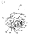
- Fig. 1 shows a disc brake 10 with a brake disc 11 and a brake pad 12.
- a cover 13 covers the brake disc 11 above a peripheral surface fourteenth the brake disk 11 partially off. This prevents the cover 13, that stones and dirt lumps caused by rotational movements of a vehicle wheel, not shown here transported to the highest point of the vehicle wheel, from above into the Disc brake 10 can get.
- the cover 13 thus prevents premature Wear of the brake disc 11 and the brake pad 12, so that the life the disc brake 10 is extended.
- the cover 13 has in the upper Vertex of the brake disc 11 a region 15, a brake carrier 16, a Brake caliper 17 and an intermediate gap 18 overlaps. Consequently prevented the area 15 of the cover 13, that stones and lumps of dirt through the gap 18th can penetrate into the disc brake 10.
- the cover member 13 extends to the right over the area 15, which extends over the upper vertex of brake disk 11 is located, down to one of here not shown in detail road facing opening 19. This is the protective effect the cover 13 greatly improved.
- the cover member 13 faces at its lower, not shown here roadway End the opening 19 through which 10 to enter the air for cooling the disc brake and can escape. Since the released from the cover 13 opening 19 below is arranged, is an undesirable entry of dirt into the disc brake 10 of their top excluded.
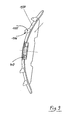
- the cover element 13 has an upper portion 20 and a lower portion 21 on (see Fig. 2). Since the dirt rather from above than from below in the Sommenbremse 10th can reach, the upper portion 20 covers the brake disc 11 over the entire Width of the peripheral surface 14 from. The wider upper portion 20 thus allows a optimal protection against unwanted entry of stones and dirt lumps. Of the lower portion 21, however, covers the brake disc 14 only partially. Here it is Dirt entering the disc brake 10 is very unlikely. The only partial Covering the brake disc 11 through the narrower lower portion 21 allows sufficient ventilation for cooling the disc brake 10th
- the cover from the upper vertex down to the end of the roadway facing the brake disc cover over the entire width of the peripheral surface. Then the cover be provided with ventilation openings that ensure adequate ventilation.
- cover 13 does not cover the brake disk 11 with one of them shown wheel rim facing inside 30 from, even on the road facing lower end in the region of the opening 19 (see Figures 1 and 3).
- the disc brake 10 is equipped with another cover member 100 (see FIGS. 1, 4 and 5).
- the further cover element 100 covers an opening 101 of a brake pad shaft 102 (see Fig. 1). Since the opening 101 above a wheel axle 103, dirt may easily enter the disc brake 10 through it.
- cover the cover 13 and the other cover 100 with their respective ends of the caliper 17 overlapping.
- at least one of the two cover elements 13, 100 at least partially except for a tolerable for dirt impassable gap be brought to the caliper 17.
- a spring element 104 is arranged between the further cover 100 and the brake pad 12.
- the cover 100 presses against the spring element 104, and the spring element 104 presses against brake pad 12th
- the cover 100 holds together with the spring element 104 the brake pad 12 in its specific position.
- the cover 100 is provided with bulges 105 in which openings 106 are located.
- the openings 106 face downward, so that only air for cooling the Disc brake 10 may occur without dirt enters the disc brake 10 (see Figures 1, 4 and 5).
- the further cover 100 is in this embodiment, in sections to a Bracket 40 (see Figures 4, 5 and 6) is formed, which is fastened to the caliper 17.
- the bracket 40 is a separate Component which the further cover member 100 in a penetration formed in the latter 99 takes up fixing.
- the cover 100 may additionally be connected via welds 98 with the separate bracket 40. This can be the hanger 40 an already present on the disc brake 10 component, for example a Hold down the brake pads.
- the cover 100 be retrofitted to conventional disc brakes.
- this bracket 40 As a bracket portion (Fig. 4 to 6) either in the cover 100 integrated or as a separate component (Fig. 7 to 9) with the cover 100 is connected, this bracket / Bügelabschnift 40 has a projection 50 which in a in the brake caliper 17 existing opening 51 engages (see Figures 4, 5, 6 and 8). It will the bracket / bracket portion 40 niedes attached to the brake caliper 17 form fit. other end is the bracket / bracket portion 40 with a bolt 60 and a split pin 61 am Brake caliper 17 attached. By the bolt 60 and the split pin 61, the further Abdekkelement 100 attached with a few simple steps on the caliper 17 and removed from this become.
- the cover 13 is screwed to a wheel 31.
- a wheel 31 For this purpose are on the cover 13 screw holes 32 provided (see Fig. 3).
- the Wheel carrier 31 can subsequently incorporated radially arranged screw thread be, so that the cover 13 enbefalls also on existing disc brakes can be retrofitted.
- Fig. 7 is a schematic and partially a perspective plan view of the disc brake 10 shown in FIG. 4.
- the further cover element 100 has a here Penetration 99, in which the separate bracket 40 passes through and the cover 100 fixed to the caliper 17.
- bracket 40 in plan view, the further cover element 100 with a separately formed, shown at this fortified by weld 98 bracket 40.
- the bracket 40 has at his one end to the projection 51 (Figs. 5 and 6) engaging projection 50 on.
- Fig. 9 is a side view of the further cover 100 with separate bracket 40 according to Fig. 8 is shown.
Landscapes
- Engineering & Computer Science (AREA)
- General Engineering & Computer Science (AREA)
- Mechanical Engineering (AREA)
- Braking Arrangements (AREA)
Abstract
Description
- Fig. 1
- eine Schnittansicht durch eine Scheibenbremse;
- Fig. 2
- eine Vorderansicht auf die Scheibenbremse aus Fig. 1;
- Fig. 3
- eine perspektivische Draufsicht auf die Scheibenbremse aus Fig. 1;
- Fig. 4
- eine persektivische Draufsicht auf die Scheibenbremse aus Fig. 1 aus einer zu Fig. 3 entgegengesetzten Perspektive;
- Fig. 5
- eine Ansicht in X-Richtung auf die Scheibenbremse aus Fig. 1;
- Fig. 6
- eine Schnittansicht auf die Scheibenbremse entlang der Schnittlinie A-A aus Fig. 1;
- Fig. 7
- schematisch und auszugsweise eine perspektivische Draufsicht auf die Scheibenbremse gemäß Fig. 4;
- Fig. 8
- in Draufsicht ein zusätzliches Abdeckelement mit angeschweißtem Bügel;
- Fig. 9
- in Seitenansicht das Abdeckelement gemäß Fig. 8.
- 10
- Scheibenbremse
- 11
- Bremsscheibe
- 12
- Bremsbelag
- 13
- Abdeckelement
- 14
- Umfangsfläche
- 15
- Bereich
- 16
- Bremsträger
- 17
- Bremssattel
- 18
- Spalt
- 19
- Öffnung
- 20
- oberer Teilbereich
- 21
- unterer Teilbereich
- 30
- Innenseite
- 31
- Radträger
- 32
- Verschraubungsöffnungen
- 40
- Bügel, separat oder in Abdeckelement 100 integriert
- 50
- Vorsprung
- 51
- Öffnung
- 60
- Bolzen
- 61
- Splint
- 98
- Verschweißung
- 99
- Durchdringung
- 100
- Abdeckelement, zusätzliches
- 101
- Öffnung
- 102
- Bremsbelagschacht
- 103
- Radachse
- 104
- Federelement
- 105
- Ausbuchtung
- 106
- Öffnung
Claims (18)
- Scheibenbremse (10) für ein Nutzfahrzeug, insbesondere für einen baustellen- und/oder geländetauglichen LKW, mit mindestens einem eine Bremsscheibe (11) mindestens teilweise abdeckenden Abdeckelement (13), dadurch gekennzeichnet, dass das mindestens eine Abdeckelement (13) oberhalb eines oberen Scheitelpunktes der Bremsscheibe (11) angeordnet ist.
- Scheibenbremse (10) nach Anspruch 1, dadurch gekennzeichnet, dass sich das mindestens eine Abdeckelement (13) über einen oberhalb des oberen Scheitelpunktes der Bremsscheibe (11) befindlichen Bereich (15) in Umfangsrichtung der Bremsscheibe (11) hinaus erstreckt.
- Scheibenbremse (10) nach Anspruch 2, dadurch gekennzeichnet, dass ein Teilbereich (20) des mindestens einen Abdeckelements (13) die gesamte Breite einer Umfangsfläche (14) der Bremsscheibe (11) abdeckt und, dass ein weiterer Teilbereich (21) des mindestens einen Abdeckelements (13) die Breite der Umfangsfläche (14) der Bremsscheibe (11) nur teilweise abdeckt.
- Scheibenbremse (10) nach Anspruch 2, dadurch gekennzeichnet, dass das mindestens eine Abdeckelement (13) die gesamte Breite der Umfangsfläche (14) der Bremsscheibe (11) abdeckt und das mindestens eine Abdeckelement (13) mit Belüftungsöffnungen versehen ist.
- Scheibenbremse (10) nach einem der Ansprüche 1 bis 4, dadurch gekennzeichnet, dass das mindestens eine Abdeckelement (13) die Bremsscheibe (11) zusätzlich mit einer einer Radfelge zugewandten Innenseite (30) mindestens teilweise abdeckt.
- Scheibenbremse (10) nach einem der Ansprüche 1 bis 5, dadurch gekennzeichnet, dass das mindestens eine Abdeckelement (13) an seinem einer Fahrbahn zugewandten Ende die Bremsscheibe (11) mindestens mit der der Radfelge zugewandten Innenseite (30) abdeckt, und dass das mindestens eine Abdeckelement (13) an dem der Fahrbahn zugewandten Ende über der Umfangsfläche (14) eine Öffnung (19) aufweist.
- Scheibenbremse (10) nach einem der Ansprüche 1 bis 6, dadurch gekennzeichnet, dass die Scheibenbremse (10) außerdem über einer Öffnung (101) eines Bremsbelagschachtes (102) ein weiteres Abdeckelement (100) aufweist.
- Scheibenbremse (10) nach Anspruch 7, dadurch gekennzeichnet, dass zwischen dem weiteren Abdeckelement (100) und einem Bremsbelag (12) ein Federelement (104) angeordnet ist.
- Scheibenbremse (10) nach Anspruch 7, dadurch gekennzeichnet, dass das weitere Abdeckelement (100) zusätzlich zum Niederhalten der Bremsbeläge (12) vorgesehen ist.
- Scheibenbremse (10) nach einem der Ansprüche 8 und 9, dadurch gekennzeichnet, dass das Abdeckelement (100) die Bremsbeläge (12) mittels des Federelementes (104) niederhält.
- Scheibenbremse (10) nach einem der Ansprüche 1 bis 10, dadurch gekennzeichnet, dass die Abdeckelemente (13,100) mit Öffnungen (106) aufweisenden Ausbuchtungen (105) versehen sind, und dass die Öffnungen (106) der Fahrbahn zugewandt sind.
- Scheibenbremse (10) nach einem der Ansprüche 1 bis 11, dadurch gekennzeichnet, dass die Abdeckelemente (13,100) nachrüstbar sind.
- Scheibenbremse (10) nach einem der Ansprüche 7 bis 12, dadurch gekennzeichnet, dass das weitere Abdeckelement (100) mittels eines an diesem gegebenen Bügels (40) am Bremssattel (17) befestigbar und vom Bremssattel (17) lösbar ist.
- Scheibenbremse (10) nach Anspruch 13, dadurch gekennzeichnet, dass der Bügel (40) einenendes einen Vorsprung (50) aufweist, der in eine am Bremssattel (17) vorhandene Öffnung (51) eingreift.
- Scheibenbremse (10) nach Anspruch 13 oder 14, dadurch gekennzeichnet, dass der Bügel (40) anderenendes mit einem Splint (61) und einem Bolzen (60) am Bremssattel (17) befestigbar und vom Bremssattel (17) lösbar ist.
- Scheibenbremse (10) nach einem oder mehreren der vorangegangenen Ansprüche 13 bis 15, dadurch gekennzeichnet, dass der am weiteren Abdeckelement (100) gegebene Bügel (40) ein einteilig mit dem Abdeckelement (100) gebildetes Bauteil ist.
- Scheibenbremse (10) nach einem oder mehreren der vorangegangenen Ansprüche 13 bis 15, dadurch gekennzeichnet, dass der am weiteren Abdeckelement (100) gegebene Bügel (40) ein separates Bauteil ist, welches mittels Befestigungsmittel wie beispielsweise Clips-, Rast-, Schweiß- oder Schraubverbindungen oder dergleichen mit dem Abdekkelement (100) verbunden ist.
- Schreibenbremse (10) nach einem der Ansprüche 1 bis 17, dadurch gekennzeichnet, dass das mindestens eine Abdeckelement (13) an einem Achsschenkel oder an einem Radträger (31) festgeschraubt ist.
Applications Claiming Priority (2)
| Application Number | Priority Date | Filing Date | Title |
|---|---|---|---|
| DE102004013310 | 2004-03-17 | ||
| DE200410013310 DE102004013310A1 (de) | 2004-03-17 | 2004-03-17 | Scheibenbremse |
Publications (2)
| Publication Number | Publication Date |
|---|---|
| EP1577578A1 true EP1577578A1 (de) | 2005-09-21 |
| EP1577578B1 EP1577578B1 (de) | 2007-05-30 |
Family
ID=34833175
Family Applications (1)
| Application Number | Title | Priority Date | Filing Date |
|---|---|---|---|
| EP20050004638 Expired - Lifetime EP1577578B1 (de) | 2004-03-17 | 2005-03-03 | Schutzabdeckung für eine Scheibenbremse und Scheibenbremse mit einer solchen Schutzabdeckung. |
Country Status (2)
| Country | Link |
|---|---|
| EP (1) | EP1577578B1 (de) |
| DE (2) | DE102004013310A1 (de) |
Cited By (7)
| Publication number | Priority date | Publication date | Assignee | Title |
|---|---|---|---|---|
| DE102005059823B3 (de) * | 2005-12-14 | 2007-03-29 | Knorr-Bremse Systeme für Nutzfahrzeuge GmbH | Scheibenbremse, insbesondere für ein Nutzfahrzeug |
| DE102006018269A1 (de) * | 2006-04-20 | 2007-10-25 | Dr.Ing.H.C. F. Porsche Ag | Schutzvorrichtung für eine Teilscheibenbremse |
| FR2900709A1 (fr) * | 2006-05-05 | 2007-11-09 | Renault Sas | Protecteur de disque pour frein a disque de vehicule automobile permettant d'eviter le blocage de projectiles entre l'etrier de frein et la jante de la roue |
| DE102005059071B4 (de) * | 2005-12-10 | 2010-04-08 | Man Nutzfahrzeuge Ag | Schutzvorrichtung für eine Bremsscheibe |
| CN101875389A (zh) * | 2010-04-02 | 2010-11-03 | 许志明 | 一种碟刹防护罩 |
| EP3534030A1 (de) * | 2018-03-02 | 2019-09-04 | ArvinMeritor Technology, LLC | Bremssattelanordnung mit haltebügel |
| CN110966324A (zh) * | 2018-09-28 | 2020-04-07 | 本田技研工业株式会社 | 车辆用制动装置 |
Families Citing this family (5)
| Publication number | Priority date | Publication date | Assignee | Title |
|---|---|---|---|---|
| DE102005060551B4 (de) * | 2005-12-17 | 2010-05-06 | MAN Nutzfahrzeuge Österreich AG | Vorrichtung zur Anzeige eines Bremsbelagverschleißes |
| DE102008022967A1 (de) | 2008-05-09 | 2009-11-12 | Knorr-Bremse Systeme für Nutzfahrzeuge GmbH | Bremsscheibenabdeckung für eine Bremsscheibe einer Scheibenbremse |
| DE102009023104C5 (de) | 2008-06-05 | 2013-08-22 | Wabco Radbremsen Gmbh | Scheibenbremse, insbesondere für Nutzfahrzeuge, sowie Abdeckung einer solchen Scheibenbremse |
| DE102008034591A1 (de) * | 2008-07-25 | 2010-01-28 | Bpw Bergische Achsen Kg | Abdeckung für die Bremsscheibe einer Fahrzeug-Scheibenbremse |
| DE102011114107C5 (de) | 2011-09-22 | 2017-07-27 | Knorr-Bremse Systeme für Nutzfahrzeuge GmbH | Bremssattel einer Scheibenbremse für ein Nutzfahrzeug |
Citations (3)
| Publication number | Priority date | Publication date | Assignee | Title |
|---|---|---|---|---|
| US3310135A (en) * | 1961-11-23 | 1967-03-21 | Girling Ltd | Spot-type disc brake |
| US4620616A (en) * | 1983-06-16 | 1986-11-04 | Dr. Ing. H.C.F. Porsche Aktiengesellschaft | Cooling device for disc brakes, especially for automotive vehicles |
| DE10102761A1 (de) * | 2001-01-23 | 2002-07-25 | Volkswagen Ag | Fahrzeugbremse |
-
2004
- 2004-03-17 DE DE200410013310 patent/DE102004013310A1/de not_active Withdrawn
-
2005
- 2005-03-03 DE DE200550000758 patent/DE502005000758D1/de not_active Expired - Lifetime
- 2005-03-03 EP EP20050004638 patent/EP1577578B1/de not_active Expired - Lifetime
Patent Citations (3)
| Publication number | Priority date | Publication date | Assignee | Title |
|---|---|---|---|---|
| US3310135A (en) * | 1961-11-23 | 1967-03-21 | Girling Ltd | Spot-type disc brake |
| US4620616A (en) * | 1983-06-16 | 1986-11-04 | Dr. Ing. H.C.F. Porsche Aktiengesellschaft | Cooling device for disc brakes, especially for automotive vehicles |
| DE10102761A1 (de) * | 2001-01-23 | 2002-07-25 | Volkswagen Ag | Fahrzeugbremse |
Cited By (11)
| Publication number | Priority date | Publication date | Assignee | Title |
|---|---|---|---|---|
| DE102005059071B4 (de) * | 2005-12-10 | 2010-04-08 | Man Nutzfahrzeuge Ag | Schutzvorrichtung für eine Bremsscheibe |
| DE102005059823B3 (de) * | 2005-12-14 | 2007-03-29 | Knorr-Bremse Systeme für Nutzfahrzeuge GmbH | Scheibenbremse, insbesondere für ein Nutzfahrzeug |
| DE102006018269A1 (de) * | 2006-04-20 | 2007-10-25 | Dr.Ing.H.C. F. Porsche Ag | Schutzvorrichtung für eine Teilscheibenbremse |
| FR2900709A1 (fr) * | 2006-05-05 | 2007-11-09 | Renault Sas | Protecteur de disque pour frein a disque de vehicule automobile permettant d'eviter le blocage de projectiles entre l'etrier de frein et la jante de la roue |
| CN101875389A (zh) * | 2010-04-02 | 2010-11-03 | 许志明 | 一种碟刹防护罩 |
| CN101875389B (zh) * | 2010-04-02 | 2013-04-17 | 许志明 | 一种碟刹防护罩 |
| EP3534030A1 (de) * | 2018-03-02 | 2019-09-04 | ArvinMeritor Technology, LLC | Bremssattelanordnung mit haltebügel |
| CN110219904A (zh) * | 2018-03-02 | 2019-09-10 | 阿文美驰技术有限责任公司 | 具有固位器托架的制动夹钳组件 |
| CN110966324A (zh) * | 2018-09-28 | 2020-04-07 | 本田技研工业株式会社 | 车辆用制动装置 |
| CN110966324B (zh) * | 2018-09-28 | 2021-11-30 | 本田技研工业株式会社 | 车辆用制动装置 |
| US11346411B2 (en) | 2018-09-28 | 2022-05-31 | Honda Motor Co., Ltd. | Braking device for vehicle |
Also Published As
| Publication number | Publication date |
|---|---|
| DE502005000758D1 (de) | 2007-07-12 |
| EP1577578B1 (de) | 2007-05-30 |
| DE102004013310A1 (de) | 2005-09-29 |
Similar Documents
| Publication | Publication Date | Title |
|---|---|---|
| EP1577578B1 (de) | Schutzabdeckung für eine Scheibenbremse und Scheibenbremse mit einer solchen Schutzabdeckung. | |
| EP3018379B1 (de) | Abschirmvorrichtung für eine bremsscheibe | |
| DE102008043354A1 (de) | Fahrradbauteil-Befestigungsstruktur | |
| DE102018114396A1 (de) | Scheibenbremse mit einer Rückstelleinrichtung und Bremsbelagsatz einer solchen Scheibenbremse | |
| DE19850257C2 (de) | Scheibenbremsenschutz einer einen Reibring aufweisenden Scheibenbremse eines Kraftfahrzeugrades mit durchbrochener Felgenschüssel | |
| EP2718582A1 (de) | Scheibenbremse, insbesondere für nutzfahrzeuge | |
| DE4024484C2 (de) | Schwimmsattel für Teilbelag-Scheibenbremse mit verriegelter Gehäusehaltefeder | |
| EP0877677B1 (de) | Vorrichtung zur verriegelung eines containers an einem fahrzeugchassis | |
| DE202022106829U1 (de) | Fahrzeugrad, insbesondere für Nutzfahrzeuge | |
| EP2499033B1 (de) | Luftaufbereitungsanlage | |
| DE1932057A1 (de) | Teilbelagscheibenbremse insbesondere fuer Kraftfahrzeuge | |
| DE102005059071B4 (de) | Schutzvorrichtung für eine Bremsscheibe | |
| DE202020005992U1 (de) | Gleitschutzvorrichtung mit externer Montage insbesondere für Räder mit Leichtmetallfelgen | |
| DE102020100139A1 (de) | Bremsbelag für eine Scheibenbremse eines Schienenfahrzeugs und Scheibenbremse | |
| DE10202778B4 (de) | Bremsträgeranordnung | |
| EP1700759B1 (de) | Sicherungseinrichtung und Sicherungsverfahren für Fahrzeuganhänger | |
| DE602004004624T2 (de) | Fahrzeugdiebstahlsicherheitsvorrichtung | |
| EP1595770B1 (de) | Kraftfahrzeug mit einer Leuchtmittelaufnahme für ein Aussenleuchtmittel | |
| DE9302971U1 (de) | Ventilschutzkappe, insbesondere für Steilschulterräder mit Scheibenbremsen | |
| DE19858244B4 (de) | Bremsscheibe für Scheibenbremsen | |
| DE102023118454B4 (de) | Fahrzeug mit windschutzscheibe und schachtanordnung | |
| DE102023131657B4 (de) | Bremsträger für eine Scheibenbremse | |
| DE3535154C2 (de) | ||
| DE102012112409A1 (de) | Schmutzfangeinrichtung für ein lenkbares Rad eines Fahrzeugs | |
| DE10019413C1 (de) | Aufhängung eines Kraftfahrzeug-Achsgetriebes |
Legal Events
| Date | Code | Title | Description |
|---|---|---|---|
| PUAI | Public reference made under article 153(3) epc to a published international application that has entered the european phase |
Free format text: ORIGINAL CODE: 0009012 |
|
| AK | Designated contracting states |
Kind code of ref document: A1 Designated state(s): AT BE BG CH CY CZ DE DK EE ES FI FR GB GR HU IE IS IT LI LT LU MC NL PL PT RO SE SI SK TR |
|
| AX | Request for extension of the european patent |
Extension state: AL BA HR LV MK YU |
|
| 17P | Request for examination filed |
Effective date: 20051025 |
|
| AKX | Designation fees paid |
Designated state(s): DE FR IT NL SE |
|
| GRAP | Despatch of communication of intention to grant a patent |
Free format text: ORIGINAL CODE: EPIDOSNIGR1 |
|
| GRAS | Grant fee paid |
Free format text: ORIGINAL CODE: EPIDOSNIGR3 |
|
| GRAA | (expected) grant |
Free format text: ORIGINAL CODE: 0009210 |
|
| AK | Designated contracting states |
Kind code of ref document: B1 Designated state(s): DE FR IT NL SE |
|
| REF | Corresponds to: |
Ref document number: 502005000758 Country of ref document: DE Date of ref document: 20070712 Kind code of ref document: P |
|
| REG | Reference to a national code |
Ref country code: SE Ref legal event code: TRGR |
|
| ET | Fr: translation filed | ||
| PLBE | No opposition filed within time limit |
Free format text: ORIGINAL CODE: 0009261 |
|
| STAA | Information on the status of an ep patent application or granted ep patent |
Free format text: STATUS: NO OPPOSITION FILED WITHIN TIME LIMIT |
|
| 26N | No opposition filed |
Effective date: 20080303 |
|
| REG | Reference to a national code |
Ref country code: NL Ref legal event code: TD Effective date: 20110420 |
|
| REG | Reference to a national code |
Ref country code: FR Ref legal event code: CD |
|
| REG | Reference to a national code |
Ref country code: DE Ref legal event code: R081 Ref document number: 502005000758 Country of ref document: DE Owner name: MAN TRUCK & BUS AG, DE Free format text: FORMER OWNER: MAN NUTZFAHRZEUGE AG, 80995 MUENCHEN, DE Effective date: 20110518 |
|
| REG | Reference to a national code |
Ref country code: FR Ref legal event code: PLFP Year of fee payment: 12 |
|
| PG25 | Lapsed in a contracting state [announced via postgrant information from national office to epo] |
Ref country code: IT Free format text: LAPSE BECAUSE OF NON-PAYMENT OF DUE FEES Effective date: 20160303 |
|
| REG | Reference to a national code |
Ref country code: FR Ref legal event code: PLFP Year of fee payment: 13 |
|
| PG25 | Lapsed in a contracting state [announced via postgrant information from national office to epo] |
Ref country code: IT Free format text: LAPSE BECAUSE OF NON-PAYMENT OF DUE FEES Effective date: 20160303 |
|
| PGRI | Patent reinstated in contracting state [announced from national office to epo] |
Ref country code: IT Effective date: 20170710 |
|
| REG | Reference to a national code |
Ref country code: FR Ref legal event code: PLFP Year of fee payment: 14 |
|
| REG | Reference to a national code |
Ref country code: DE Ref legal event code: R081 Ref document number: 502005000758 Country of ref document: DE Owner name: MAN TRUCK & BUS SE, DE Free format text: FORMER OWNER: MAN TRUCK & BUS AG, 80995 MUENCHEN, DE |
|
| PGFP | Annual fee paid to national office [announced via postgrant information from national office to epo] |
Ref country code: NL Payment date: 20240326 Year of fee payment: 20 |
|
| PGFP | Annual fee paid to national office [announced via postgrant information from national office to epo] |
Ref country code: DE Payment date: 20240328 Year of fee payment: 20 |
|
| PGFP | Annual fee paid to national office [announced via postgrant information from national office to epo] |
Ref country code: SE Payment date: 20240326 Year of fee payment: 20 Ref country code: IT Payment date: 20240321 Year of fee payment: 20 Ref country code: FR Payment date: 20240326 Year of fee payment: 20 |
|
| REG | Reference to a national code |
Ref country code: DE Ref legal event code: R071 Ref document number: 502005000758 Country of ref document: DE |
|
| REG | Reference to a national code |
Ref country code: NL Ref legal event code: MK Effective date: 20250302 |
|
| REG | Reference to a national code |
Ref country code: SE Ref legal event code: EUG |