EP1577243B1 - Dispositif pour alimenter une pile à une station de traitement ultérieur - Google Patents
Dispositif pour alimenter une pile à une station de traitement ultérieur Download PDFInfo
- Publication number
- EP1577243B1 EP1577243B1 EP04006046A EP04006046A EP1577243B1 EP 1577243 B1 EP1577243 B1 EP 1577243B1 EP 04006046 A EP04006046 A EP 04006046A EP 04006046 A EP04006046 A EP 04006046A EP 1577243 B1 EP1577243 B1 EP 1577243B1
- Authority
- EP
- European Patent Office
- Prior art keywords
- table part
- stack
- feed
- segments
- separating
- Prior art date
- Legal status (The legal status is an assumption and is not a legal conclusion. Google has not performed a legal analysis and makes no representation as to the accuracy of the status listed.)
- Expired - Lifetime
Links
- 238000012545 processing Methods 0.000 title claims abstract description 17
- 238000000926 separation method Methods 0.000 description 7
- 239000011111 cardboard Substances 0.000 description 6
- 239000011087 paperboard Substances 0.000 description 3
- 238000012805 post-processing Methods 0.000 description 2
- 238000004080 punching Methods 0.000 description 2
- 238000010521 absorption reaction Methods 0.000 description 1
- 230000015572 biosynthetic process Effects 0.000 description 1
- 238000007599 discharging Methods 0.000 description 1
- 238000006073 displacement reaction Methods 0.000 description 1
- 230000000694 effects Effects 0.000 description 1
- 230000001788 irregular Effects 0.000 description 1
- 235000021190 leftovers Nutrition 0.000 description 1
- 238000000034 method Methods 0.000 description 1
- 238000004806 packaging method and process Methods 0.000 description 1
- 239000000123 paper Substances 0.000 description 1
- 239000002985 plastic film Substances 0.000 description 1
- 229920006255 plastic film Polymers 0.000 description 1
- 230000008092 positive effect Effects 0.000 description 1
- 230000000284 resting effect Effects 0.000 description 1
- 230000000630 rising effect Effects 0.000 description 1
- 238000005096 rolling process Methods 0.000 description 1
- 210000002023 somite Anatomy 0.000 description 1
- 230000007704 transition Effects 0.000 description 1
Images


Classifications
-
- B—PERFORMING OPERATIONS; TRANSPORTING
- B65—CONVEYING; PACKING; STORING; HANDLING THIN OR FILAMENTARY MATERIAL
- B65H—HANDLING THIN OR FILAMENTARY MATERIAL, e.g. SHEETS, WEBS, CABLES
- B65H31/00—Pile receivers
- B65H31/30—Arrangements for removing completed piles
- B65H31/3081—Arrangements for removing completed piles by acting on edge of the pile for moving it along a surface, e.g. by pushing
-
- B—PERFORMING OPERATIONS; TRANSPORTING
- B65—CONVEYING; PACKING; STORING; HANDLING THIN OR FILAMENTARY MATERIAL
- B65H—HANDLING THIN OR FILAMENTARY MATERIAL, e.g. SHEETS, WEBS, CABLES
- B65H31/00—Pile receivers
- B65H31/30—Arrangements for removing completed piles
- B65H31/309—Arrangements for removing completed piles by acting on one of the outermost articles for moving the pile of articles on edge along a surface, e.g. by pushing
-
- B—PERFORMING OPERATIONS; TRANSPORTING
- B65—CONVEYING; PACKING; STORING; HANDLING THIN OR FILAMENTARY MATERIAL
- B65H—HANDLING THIN OR FILAMENTARY MATERIAL, e.g. SHEETS, WEBS, CABLES
- B65H2301/00—Handling processes for sheets or webs
- B65H2301/40—Type of handling process
- B65H2301/42—Piling, depiling, handling piles
- B65H2301/422—Handling piles, sets or stacks of articles
- B65H2301/4225—Handling piles, sets or stacks of articles in or on special supports
- B65H2301/42256—Pallets; Skids; Platforms with feet, i.e. handled together with the stack
-
- B—PERFORMING OPERATIONS; TRANSPORTING
- B65—CONVEYING; PACKING; STORING; HANDLING THIN OR FILAMENTARY MATERIAL
- B65H—HANDLING THIN OR FILAMENTARY MATERIAL, e.g. SHEETS, WEBS, CABLES
- B65H2301/00—Handling processes for sheets or webs
- B65H2301/40—Type of handling process
- B65H2301/42—Piling, depiling, handling piles
- B65H2301/422—Handling piles, sets or stacks of articles
- B65H2301/4226—Delivering, advancing piles
- B65H2301/42266—Delivering, advancing piles by acting on edge of the pile for moving it along a surface, e.g. pushing
-
- B—PERFORMING OPERATIONS; TRANSPORTING
- B65—CONVEYING; PACKING; STORING; HANDLING THIN OR FILAMENTARY MATERIAL
- B65H—HANDLING THIN OR FILAMENTARY MATERIAL, e.g. SHEETS, WEBS, CABLES
- B65H2301/00—Handling processes for sheets or webs
- B65H2301/40—Type of handling process
- B65H2301/42—Piling, depiling, handling piles
- B65H2301/422—Handling piles, sets or stacks of articles
- B65H2301/4226—Delivering, advancing piles
- B65H2301/42268—Delivering, advancing piles by acting on one of the outermost article for moving pile of articles on edge along a surface, e.g. pushing
-
- B—PERFORMING OPERATIONS; TRANSPORTING
- B65—CONVEYING; PACKING; STORING; HANDLING THIN OR FILAMENTARY MATERIAL
- B65H—HANDLING THIN OR FILAMENTARY MATERIAL, e.g. SHEETS, WEBS, CABLES
- B65H2701/00—Handled material; Storage means
- B65H2701/10—Handled articles or webs
- B65H2701/17—Nature of material
- B65H2701/176—Cardboard
Definitions
- the invention relates to a device for feeding a stack comprising a plurality of individual sheets to a further processing station, with a table receiving the stack and a feed slide for moving the stack to the further processing station.
- a resting on a cardboard backing total stack which is formed from a plurality of individual sheets.
- the cuts are made in a first direction, then the total stack formed from the individual stacks rotated 90 degrees and then cut transversely to the extension of the first cutting sequences, so that in this case a variety of benefit stacks are generated.
- Each benefit stack consists of the large number of individual sheets, whereby the lower cardboard layer is also subsumed under the term of the single sheet. On this box are the large number of sheets, such as cut labels, which are later stuck on bottles, cans, etc.
- Devices for cutting entire stacks to form a plurality of benefit stacks are known, for example, from WO 91/00168 and EP 0 453 933 A1.
- a device according to the preamble of claim 1 is known from EP-A-1 018 409.
- the cut benefit stacks are fed to a further processing station, which is for example a banding station.
- the benefit stacks are banded so that they can be handled better for the purpose of further processing, especially the individual sheets of the benefit stack can not move against each other.
- the further processing can also include a punching process.
- only cuboid structures can be created when cutting the total stack in the individual benefit stack. If the individual label but not a rectangular shape, but have an irregular, such as oval or circular shape, it is necessary to punch the stack of benefits.
- a device for feeding a stack of benefits to a further processing station with the features of the type mentioned is known from DE 42 41 800 A1. There, the feed slide an intermediate plate is assigned, which serves to receive the further benefit stack to be processed. These Design serves the purpose of avoiding the rolling of the bottom stack sheets when hitting less slippery documents.
- a carton can form the bottom layer of the benefit stack. It is also conceivable to provide no cardboard, so that the benefit stack is formed only from the individual sheets to be further processed, in particular labels. It is also conceivable to stack several benefit stacks one on top of the other for further processing and then to band them.
- the arrangement of the stack of benefits one above the other in the stacked total stack individual boxes, according to the arrangement of the individual stack of piles above each other. - In the further processing different demands can be made: So on the one hand there may be the desire to supply the post-processing station only benefit stack without bottom cardboard. On the other hand, there may be a desire to always supply benefit stacks with bottom paperboard.
- the object of the invention is to form a device of the type mentioned so that it can be separated from the remaining, in particular formed by the individual sheets remaining stack with this when needed in the stack of benefits a thick-walled recording, whereby only the remainder of the post-processing station is fed.
- a thick-walled recording is in particular the aforementioned cardboard to understand, which is therefore designed differently than the remaining single sheets, which are in particular labels.
- the table has a first and a second table part, wherein the second table part in the region of its end facing the first table part a directed against the feed direction of the feed slider separating wedge, and between the facing ends of the two table parts, a height gap is formed, wherein the pointed edge of the separating wedge is at a higher level than the separating wedge facing the end of the first table part.
- the higher level is adjusted so that it corresponds to the thickness of the thick-walled recording.
- the thickness of the thick-walled receptacle for the residual stack formed by the individual sheets is 0.5 to 2 mm, preferably 0.5 to 1.5 mm, in particular 1 mm. These dimensions thus also correspond to the dimensions of the height gap.
- a rising in the feed direction of the feed slider step is formed, which has due to the formation of the interested table part as a separating wedge, the thick-walled recording of the remaining individual sheets of the benefit stack separated and through the height gap, thus the gap between the two Table parts, is conveyed down.
- the feeding slide conveys only the remaining individual sheets of the useful stack, thus the residual stack formed by them, to the further processing station.
- the two table parts are adjusted to one another such that no height gap is formed.
- the feed slide thus promotes the benefit stack, without the action of the second table part, the further processing station.
- the separating wedge forms part of a separating knife, wherein the separating knife forms part of the second table part.
- the upper surface of the table thus the upper surfaces of the two table members adjacent to the height gap, form a plane which extends horizontally.
- the second table part is stationary.
- This table part should cooperate with an adjusting device, which serves for the vertical adjustment of the second table part with respect to the first table part. With the adjusting device can thus achieve the fine adjustment of the two table parts.
- the first table part when the second table part is stationary, it is considered to be particularly advantageous if the first table part, at least in the region of its end facing the second table part, can be raised and lowered. Consequently, it is only important that the first table part in the region of its end, which faces the second table part, can be raised and lowered. This corresponds to the requirement that only the pointed edge of the separating part of the second table part must be liftable and lowerable relative to the first table part; this is achieved in the stationarily arranged second table part by the movement of the first table part. Of course, there is the possibility to raise and lower the first table part in total.
- the raising and lowering of the first table part is expediently carried out by pneumatic power means.
- the first table part consists of several, in particular three segments, which are hinged together.
- the first table part can not be raised and lowered as a whole, but, in order to ensure the functionality, only the segment adjacent to the second table part for forming the height gap must be movable, while the other segments of the first table part follow this one segment due to their articulated connection.
- the first table part has a curved upper surface and, with the height gap formed, is oriented in particular horizontally with the upper surfaces of the segments.
- the articulated connection of the segments is formed in particular by leaf springs which connect adjacent segments with each other.
- a further preferred embodiment of the device relates to the arrangement of the dividing line between the first table part and the second table part.
- the dividing line subtends an angle with the feed direction of the feed pusher of 70-80 degrees.
- the dividing line between the first part of the table and the second part of the table should be stepped. This arrangement causes extremely positive effects when separating the thick-walled recording of the remaining residue stack of the benefit stack.
- the second table part is formed by a plurality of segments, in particular parallelogram-shaped segments, wherein the segments are oriented in the feed direction of the feed slider.
- the first segment of the second table part first encounters the benefit stack promoted against it, namely in the region of a vertical edge of the benefit stack.
- the horizontally oblique arrangement of the separating wedge causes, with respect to the first segment, the separation process extends over part of the width of the benefit stack.
- the adjacent segment which is arranged at a lateral distance from the first segment, effective.
- This adjacent segment which is offset from the first segment, moves into the wedge-shaped gap already spread by the first segment between the receptacle and the remaining stack, with the result that the separation process takes place only by means of the first segment.
- the third segment becomes effective in the manner of the second segment.
- the feed slide can optimally act on the stack of benefits when the table parts or the segments of the first table part in the feed direction of the feed slider have running grooves or between the segments of the second table part in the feed direction of the feed slide extending gaps are formed.
- the grooves or gaps serve to receive slide plates of the feed slide, which can be brought into contact with the benefit stack.
- This design ensures that the slide plates extend with their effective range to below the receiving level of the stack of benefits on the table, so that the slide plates safely contact the thick-walled receptacle and the remaining stack. This contacting is independent of the position of the two table parts to each other, that is, regardless of whether the height gap is formed or not.
- the table is inclined laterally to the horizontal and it serves a connected to the table side stop the lateral abutment of the benefit stack.
- the table is inclined at an angle ⁇ of 40 to 70 °, preferably 60 to 70 °, in particular 65 ° to the horizontal.
- This quite strong inclination of the table requires that the vertically directed resulting weight of the stack is positioned at a small distance from the horizontal lower edge of the stack, so that the residual stack rests on the thick-walled receptacle with only a relatively small weight. This facilitates the separation of the thick-walled recording from the remaining stack by means of the separating wedge.
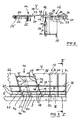
- Tisch1 and side stop 3 have upper surfaces 4 and 5, which are arranged at right angles to each other, so that they serve to receive a cuboid benefit stack.
- a feed slide 6 is in the feed direction, which is perpendicular to the sheet plane of Figure 1, opposite to the line of sight on the sheet, extends and in Figures 2 and 3 is illustrated with the arrow Y, movable.
- the feed slide 6 has a carriage 7 movably mounted in a frame, which is not shown in more detail, and three slide plates 8, which are connected to the slide 7.
- the slide plates 8 are positioned parallel to the upper surface 5 of the side stop 3, wherein the slide surfaces facing away from the slide 9 (see Figure 4) coincide with a perpendicular to the upper surface 5 of the side stop 3 and perpendicular to the upper surface 4 of the table 1 level.
- the sliding surfaces 9 is thus the task to contact a stack of benefits 10 or a residual stack 11, thus reduced by a thick-walled receptacle 12 benefits stack 10, in the region of a surface of the stack, the main surface of the slide plate 8 perpendicular to the leaf level of the individual leaves 13th of the stack 10 and 11 is oriented.
- the respective sheet 13 consists for example of paper, plastic film and the like, the receptacle 12 made of cardboard.
- the table 1 consists of two table parts 14 and 15, wherein, based on the feed direction of the feed slide 6, the first table part 15 is arranged at the front and the second table part 14 at the rear.
- the table part 14 has, in the region of its end facing the table part 15, a separating wedge 16 directed towards the table part 15. Between the facing ends of the two table parts 14 and 15, in the state shown in Figures 2, 3 and 4, a height gap 17 is formed.
- the pointed edge 18 of the separating wedge 16 is located at a higher level than the separating wedge 16 facing the end 19 of the table part 15.
- the separating wedge 16 forms part of a separating knife 20, which held a plurality of screw 21 in a further section 22 of the table part 14 is in a return of the section 22, wherein from the upper surface 23 of the separating knife 20 to the upper surface 24 of the further portion 22 results in a jump down.
- the upper surfaces 23 and 24 are horizontal.
- the further section 22 is mounted in a stationary bearing plate 25. By means of a set screw 26, the further section 22 together with the cutting blade 20 can be slightly adjusted to the bearing plate 25 so that an adjustment of the sharp edge 18 of the cutting blade 20 with respect to the upper edge 27 of the table part 15 is possible, the immediate are adjacent.
- This adjustment takes place, for example, based on the raised adjustment of the sharp edge 18 of the cutting blade for discharging the receptacle 12 to the effect that a receptacle 12 placed between the bearing plate 25 and the other portion 22 and the screw 26 is adjusted such that this recording 12 straight between the bearing plate 25 and the portion 22 is clamped.
- the adjustment of the pointed edge 18 of the cutting blade 20, such that the edge 18 is at the same level to the upper edge 27 of the first table part 15, suitably takes place in that the portion 22 is positioned by means of the adjusting screw 26 against the bearing plate 25.
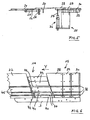
- the first table part 15 is in the region of its end 19, specifically its upper edge 27, raised and lowered.
- the table part 15 consists of three segments 28, 29 and 30, wherein adjacent segments 28 and 29 or 29 and 30 are connected to each other on their underside by means of leaf springs 31.
- fastening means 32 By means of fastening means 32, the attachment of the respective leaf spring 31 takes place at the two associated segments.
- the table part 15 is lowered, the three segments 28, 29 and 30 rest on a stationary bearing plate 33. Attached is the table part 15 with the bearing plate 33 in the region of the segment 30 by means of fastening means 34.
- a bearing receptacle 35 is attached, which serves to receive a pneumatic cylinder 36. Its piston rod 37 engages the underside of the front segment 28.
- the respective segment 28 or 29 or 30 is provided with three parallel to the upper surface 5 of the side stop 3 extending grooves 38, which serve to receive the three slide plates 8.
- the first groove of the respective segment is arranged relatively close to the side stop 3, while the second groove has such a distance from the first groove, which corresponds approximately to the distance of the first groove from the side stop 3.
- the distance of the third groove from the second groove is about as large as the distance of the second groove from the side stop 3 and extends approximately to half the width of the respective segment.
- the segments 29 and 30 have a rectangular surface, while the front segment 28, although a parallel to the segments 29 and 30 extending rear edge, but an obliquely arranged front edge, with the Reference numeral 19 is designated comprises.
- the separating knife 20 has a substantially parallelogram shape, wherein the oblique sides of the parallelogram are formed on the one hand by the oblique arrangement of the end 19 of the segment 28 and on the other hand by the oblique arrangement of the portion 22 in the region of the recess for receiving the separating knife 20.
- the separating knife 20 consists of four individual parallelogram-shaped separating knife parts 40, 41, 42 and 43, which are screwed by means of fastening means 21 with the portion 22.
- a gap 44 is formed between the side stop 3 adjacent the first separating blade portion 40 and this adjacent separating blade portion 41, which extends in the extension of the groove 38 and the recording of the side stop 3 adjacent slide plate 8 is used.
- the portion 22 is provided with three grooves 45 for receiving the slide plates 8 during their displacement.
- the four separating knife parts 40 to 43 are positioned at a short distance from the segment 28 and thus follow the protrusions 39 formed there in the sense of recesses 46.
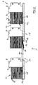
- FIG. 2 and 3 illustrate the device with formed height gap 17, which is adjusted according to the thickness of the thick-walled receptacle 12 to about 1 mm.
- the adjustment is carried out via the adjusting screws 26.
- the benefit stack 10 is conveyed, as illustrated in FIG. 4 for this application and three states, by means of the slide plates 8 of the feed slide 6, wherein the slide plates 8 first engage in the grooves 38 of the table part 15.
- the benefit stack 10 is formed by the thick-walled receptacle 12 and lying on this single sheets 13, which constitute the remaining stack 11. When advancing the stack of benefits 10 this enters the range of the height gap 17.
- the first table part 15 is raised, so that no height gap 17 exists. This state is illustrated in FIGS. 5 to 7.
- the front segment 28 is raised, wherein the central segment 29 is slightly raised with its front end due to the attachment of the segments by means of the leaf springs 31.
- the stack of benefits 10 slides this on the slope in the region of the segments 28 and 29 upwards and is without a jump in level between the front end of the segment 28th and the separating wedge 16 is pushed onto the separating knife 20.
- the benefit stack 10 is consequently supplied unchanged to the further processing station, which is not illustrated as such in the figures.
Landscapes
- Engineering & Computer Science (AREA)
- Mechanical Engineering (AREA)
- Sheets, Magazines, And Separation Thereof (AREA)
- Ticket-Dispensing Machines (AREA)
- Branching, Merging, And Special Transfer Between Conveyors (AREA)
- Controlling Sheets Or Webs (AREA)
Claims (15)
- Dispositif pour amener une pile (10) constituée d'un certain nombre de feuilles individuelles (13) à une station de traitement ultérieur, comprenant une table (1) recevant la pile (10) et un coulisseau d'amenée (6) pour déplacer la pile (10) sur la table (1) jusqu'à la station de traitement ultérieur, la table (1) étant composée d'une première partie de table (15) et d'une seconde partie de table (14),
caractérisé en ce que
la seconde partie de table (14) présente dans la zone de son extrémité située vers la première partie de table (15) un coin de séparation (16) dirigé à l'opposé du sens d'amenée du coulisseau d'amenée (6) et entre les extrémités en regard (18, 19) des deux parties de table (15, 14) peut être formée une fente en hauteur (17), l'arête en pointe du coin de séparation (16) se trouvant à un niveau plus élevé que l'extrémité (19) de la première partie de table (15) située en regard du coin de séparation (16). - Dispositif selon la revendication 1,
caractérisé en ce que
le coin de séparation (16) est un composant d'un couteau de séparation (20) qui lui-même est un composant de la seconde partie de table (14). - Dispositif selon la revendication 1 ou 2,
caractérisé en ce que
la seconde partie de table (14) est stationnaire. - Dispositif selon la revendication 1 ou 2,
caractérisé en ce que
la seconde partie de table (14) coopère avec un dispositif d'ajustage (26) qui assure l'ajustage vertical de la seconde partie de table (14) par rapport à la première partie de table (15). - Dispositif selon une des revendications 1 à 4,
caractérisé en ce que
dans la seconde partie de table (14), la surface supérieure (23) qui reçoit la pile (10) ou (11) est horizontale. - Dispositif selon une des revendications 1 à 5,
caractérisé en ce que
la première partie de table (15), au moins dans la zone de son extrémité (19) située vers la seconde partie de table (14), peut être élevée et abaissée. - Dispositif selon la revendication 6,
caractérisé en ce que
des moyens pneumatiques de levage (36) élèvent et abaissent la première partie de table (15). - Dispositif une des revendications 1 à 7,
caractérisé en ce que
la première partie de table (15) est composée de plusieurs segments, notamment trois segments (28, 29, 30), articulés notamment par des ressorts à lame (31). - Dispositif selon une des revendications 1 à 8,
caractérisé en ce que
la ligne de séparation entre la première partie de table (15) et la seconde partie de table (14) fait un angle de 70° à 80° avec la direction de déplacement (Y) du coulisseau d'amenée (6). - Dispositif selon une des revendications 1 à 9,
caractérisé en ce que
la ligne de séparation entre la première partie de table (15) et la seconde partie de table (14) est étagée. - Dispositif selon une des revendications 1 à 10,
caractérisé en ce que
la seconde partie de table (14) est constituée de plusieurs segments (40, 41, 42, 43), ayant notamment la forme de parallélogramme, ces segments étant orientés selon la direction de déplacement (Y) du coulisseau d'amenée (6). - Dispositif selon une des revendications 1 à 11,
caractérisé en ce que
la table (1) est inclinée latéralement par rapport à l'horizontale et une butée latérale (3) reliée à la table (1) sert d'appui latéral à la pile en service (10). - Dispositif selon la revendication 12,
caractérisé en ce que
la table (1) est inclinée par rapport à l'horizontale d'un angle (α) compris entre 40° et 70°, de préférence entre 60° et 70°, et notamment égal à 65°. - Dispositif selon une des revendications 11 à 13,
caractérisé en ce que
les parties de table (14, 15) ou les segments (28, 29, 30) de la première partie de table (15) présentent des rainures (38) parallèles à la direction de déplacement (Y) du coulisseau d'amenée (6) ou bien, entre les segments (40, 41, 42, 43) de la seconde partie de table (14) sont formées des fentes (44) parallèles à la direction de déplacement (Y) du tiroir d'amenée (6), les rainures (38) ou les fentes (44) servant à accueillir des plaques de coulissement (8) du coulisseau d'amenée (6) qui peuvent être amenées en contact avec la pile en service (10). - Dispositif selon une des revendications 1 à 14,
caractérisé en ce que
la fente en hauteur (17) a une dimension verticale allant de 0,5 mm à 2 mm, de préférence de 0,5 mm à 1,5 mm, et égale notamment à 1 mm.
Priority Applications (3)
| Application Number | Priority Date | Filing Date | Title |
|---|---|---|---|
| DE502004001039T DE502004001039D1 (de) | 2004-03-15 | 2004-03-15 | Vorrichtung zum Zuführen eines Stapels zu einer Weiterverarbeitungsstation |
| AT04006046T ATE334096T1 (de) | 2004-03-15 | 2004-03-15 | Vorrichtung zum zuführen eines stapels zu einer weiterverarbeitungsstation |
| EP04006046A EP1577243B1 (fr) | 2004-03-15 | 2004-03-15 | Dispositif pour alimenter une pile à une station de traitement ultérieur |
Applications Claiming Priority (1)
| Application Number | Priority Date | Filing Date | Title |
|---|---|---|---|
| EP04006046A EP1577243B1 (fr) | 2004-03-15 | 2004-03-15 | Dispositif pour alimenter une pile à une station de traitement ultérieur |
Publications (2)
| Publication Number | Publication Date |
|---|---|
| EP1577243A1 EP1577243A1 (fr) | 2005-09-21 |
| EP1577243B1 true EP1577243B1 (fr) | 2006-07-26 |
Family
ID=34833595
Family Applications (1)
| Application Number | Title | Priority Date | Filing Date |
|---|---|---|---|
| EP04006046A Expired - Lifetime EP1577243B1 (fr) | 2004-03-15 | 2004-03-15 | Dispositif pour alimenter une pile à une station de traitement ultérieur |
Country Status (3)
| Country | Link |
|---|---|
| EP (1) | EP1577243B1 (fr) |
| AT (1) | ATE334096T1 (fr) |
| DE (1) | DE502004001039D1 (fr) |
Families Citing this family (1)
| Publication number | Priority date | Publication date | Assignee | Title |
|---|---|---|---|---|
| EP2660176B1 (fr) | 2012-05-02 | 2014-10-22 | Adolf Mohr Maschinenfabrik GmbH & Co. KG | Dispositif de transport de piles carrées de feuilles individuelles vers une station de traitement |
Family Cites Families (3)
| Publication number | Priority date | Publication date | Assignee | Title |
|---|---|---|---|---|
| US3690475A (en) * | 1971-01-20 | 1972-09-12 | Sickinger Co Hans | Mechanism for dividing stacks of paper sheets |
| DE4241800A1 (de) * | 1992-12-11 | 1994-06-16 | Busch Gerhard Gmbh | Zuführvorrichtung für aus einer Vielzahl von Einzelblättern bestehenden Nutzenstapeln zur Weiterverarbeitung, mit einem einem Zuführschieber zugeordneten Zwischenblech |
| DE59807671D1 (de) * | 1998-12-28 | 2003-04-30 | Mohr Adolf Maschf | Verfahren zur Bildung und Weiterverarbeitung von kleinen Blattgutstapeln |
-
2004
- 2004-03-15 AT AT04006046T patent/ATE334096T1/de not_active IP Right Cessation
- 2004-03-15 DE DE502004001039T patent/DE502004001039D1/de not_active Expired - Lifetime
- 2004-03-15 EP EP04006046A patent/EP1577243B1/fr not_active Expired - Lifetime
Also Published As
| Publication number | Publication date |
|---|---|
| EP1577243A1 (fr) | 2005-09-21 |
| ATE334096T1 (de) | 2006-08-15 |
| DE502004001039D1 (de) | 2006-09-07 |
Similar Documents
| Publication | Publication Date | Title |
|---|---|---|
| EP0056874B2 (fr) | Machine pour couper le papier etc. | |
| EP0453933B1 (fr) | Dispositif pour couper des produits lamellaires empilés | |
| DE4038133C2 (fr) | ||
| AT505210B1 (de) | Zuführeinrichtung für plattenförmige werkstücke und werkzeugmaschine mit einer solchen zuführeinrichtung | |
| EP1018409B1 (fr) | Procédé pour la formation et le traitement ultérieur de petites piles de produits en feuilles | |
| EP0438736B1 (fr) | Disposif pour trancher du matériel lamellé superposé avec un refouleur à aligner | |
| DE69508314T2 (de) | Bewegliches Oberwerkzeug zur Trennung der Schnittschablonen von einem Bogen, der durch eine Presse zur Herstellung von Verpackungsmaterial bearbeitet ist | |
| EP0270493A2 (fr) | Cisaille d'angle | |
| CH694504A5 (de) | Verfahren zum Schneiden von Blechtafeln zu Blechstreifen sowie Schneidevorrichtung zu dessen Durchfuehrung. | |
| EP1577243B1 (fr) | Dispositif pour alimenter une pile à une station de traitement ultérieur | |
| EP2123412B1 (fr) | Machine de coupe destinée à la coupe de articles empilés, en forme de feuilles, et procédé | |
| EP4412807B1 (fr) | Découpeuse pour pilles de feuilles comprenant un élément de support | |
| DE202004015190U1 (de) | Magazin für gestapelte Zuschnitte aus Pappe, Karton o.dgl. | |
| DE2808948A1 (de) | Vorrichtung zum aufeinanderschichten von lagen aus papierbogen | |
| DE1549744C3 (de) | Vorrichtung zum einzelnen Zuführen aufgestapelter Aufzeichnungsträger | |
| DE3541623C1 (de) | Magazin für Stapel von Blechteilen, insbesondere für die Herstellung von Dosen | |
| EP1584432B1 (fr) | Presse de découpe pour découper une pile de feuilles massicotées au préalable | |
| EP1577063B1 (fr) | Poinçonneuse pour le découpage du contour de piles de flans prédécoupés | |
| DE4422194C1 (de) | Schneidverfahren für gestapeltes, blättriges Gut | |
| DE3217159A1 (de) | Vorrichtung zum zerteilen flacher, quaderfoermiger riegel in kleinere, flache quaderfoermige platten | |
| DE4101436A1 (de) | Vorrichtung zum ablegen von kopieblaettern | |
| DE3941477A1 (de) | Vorrichtung zum ablegen von kopieblaettern | |
| EP2436623B1 (fr) | Procédé et dispositif pour enlever une rangée de piles | |
| AT403556B (de) | Einrichtung zum beschicken von werkzeugmaschinen, insbesondere von sägemaschinen | |
| DE3921882C2 (fr) |
Legal Events
| Date | Code | Title | Description |
|---|---|---|---|
| PUAI | Public reference made under article 153(3) epc to a published international application that has entered the european phase |
Free format text: ORIGINAL CODE: 0009012 |
|
| 17P | Request for examination filed |
Effective date: 20050308 |
|
| AK | Designated contracting states |
Kind code of ref document: A1 Designated state(s): AT BE BG CH CY CZ DE DK EE ES FI FR GB GR HU IE IT LI LU MC NL PL PT RO SE SI SK TR |
|
| AX | Request for extension of the european patent |
Extension state: AL LT LV MK |
|
| GRAP | Despatch of communication of intention to grant a patent |
Free format text: ORIGINAL CODE: EPIDOSNIGR1 |
|
| AKX | Designation fees paid |
Designated state(s): AT BE BG CH CY CZ DE DK EE ES FI FR GB GR HU IE IT LI LU MC NL PL PT RO SE SI SK TR |
|
| GRAS | Grant fee paid |
Free format text: ORIGINAL CODE: EPIDOSNIGR3 |
|
| GRAA | (expected) grant |
Free format text: ORIGINAL CODE: 0009210 |
|
| AK | Designated contracting states |
Kind code of ref document: B1 Designated state(s): AT BE BG CH CY CZ DE DK EE ES FI FR GB GR HU IE IT LI LU MC NL PL PT RO SE SI SK TR |
|
| PG25 | Lapsed in a contracting state [announced via postgrant information from national office to epo] |
Ref country code: SI Free format text: LAPSE BECAUSE OF FAILURE TO SUBMIT A TRANSLATION OF THE DESCRIPTION OR TO PAY THE FEE WITHIN THE PRESCRIBED TIME-LIMIT Effective date: 20060726 Ref country code: RO Free format text: LAPSE BECAUSE OF FAILURE TO SUBMIT A TRANSLATION OF THE DESCRIPTION OR TO PAY THE FEE WITHIN THE PRESCRIBED TIME-LIMIT Effective date: 20060726 Ref country code: PL Free format text: LAPSE BECAUSE OF FAILURE TO SUBMIT A TRANSLATION OF THE DESCRIPTION OR TO PAY THE FEE WITHIN THE PRESCRIBED TIME-LIMIT Effective date: 20060726 Ref country code: NL Free format text: LAPSE BECAUSE OF FAILURE TO SUBMIT A TRANSLATION OF THE DESCRIPTION OR TO PAY THE FEE WITHIN THE PRESCRIBED TIME-LIMIT Effective date: 20060726 Ref country code: IE Free format text: LAPSE BECAUSE OF FAILURE TO SUBMIT A TRANSLATION OF THE DESCRIPTION OR TO PAY THE FEE WITHIN THE PRESCRIBED TIME-LIMIT Effective date: 20060726 Ref country code: IT Free format text: LAPSE BECAUSE OF FAILURE TO SUBMIT A TRANSLATION OF THE DESCRIPTION OR TO PAY THE FEE WITHIN THE PRESCRIBED TIME-LIMIT;WARNING: LAPSES OF ITALIAN PATENTS WITH EFFECTIVE DATE BEFORE 2007 MAY HAVE OCCURRED AT ANY TIME BEFORE 2007. THE CORRECT EFFECTIVE DATE MAY BE DIFFERENT FROM THE ONE RECORDED. Effective date: 20060726 Ref country code: FI Free format text: LAPSE BECAUSE OF FAILURE TO SUBMIT A TRANSLATION OF THE DESCRIPTION OR TO PAY THE FEE WITHIN THE PRESCRIBED TIME-LIMIT Effective date: 20060726 Ref country code: CZ Free format text: LAPSE BECAUSE OF FAILURE TO SUBMIT A TRANSLATION OF THE DESCRIPTION OR TO PAY THE FEE WITHIN THE PRESCRIBED TIME-LIMIT Effective date: 20060726 Ref country code: SK Free format text: LAPSE BECAUSE OF FAILURE TO SUBMIT A TRANSLATION OF THE DESCRIPTION OR TO PAY THE FEE WITHIN THE PRESCRIBED TIME-LIMIT Effective date: 20060726 |
|
| REG | Reference to a national code |
Ref country code: GB Ref legal event code: FG4D Free format text: NOT ENGLISH |
|
| REG | Reference to a national code |
Ref country code: CH Ref legal event code: EP |
|
| REG | Reference to a national code |
Ref country code: IE Ref legal event code: FG4D Free format text: LANGUAGE OF EP DOCUMENT: GERMAN |
|
| REF | Corresponds to: |
Ref document number: 502004001039 Country of ref document: DE Date of ref document: 20060907 Kind code of ref document: P |
|
| PG25 | Lapsed in a contracting state [announced via postgrant information from national office to epo] |
Ref country code: SE Free format text: LAPSE BECAUSE OF FAILURE TO SUBMIT A TRANSLATION OF THE DESCRIPTION OR TO PAY THE FEE WITHIN THE PRESCRIBED TIME-LIMIT Effective date: 20061026 Ref country code: BG Free format text: LAPSE BECAUSE OF FAILURE TO SUBMIT A TRANSLATION OF THE DESCRIPTION OR TO PAY THE FEE WITHIN THE PRESCRIBED TIME-LIMIT Effective date: 20061026 Ref country code: DK Free format text: LAPSE BECAUSE OF FAILURE TO SUBMIT A TRANSLATION OF THE DESCRIPTION OR TO PAY THE FEE WITHIN THE PRESCRIBED TIME-LIMIT Effective date: 20061026 |
|
| PG25 | Lapsed in a contracting state [announced via postgrant information from national office to epo] |
Ref country code: ES Free format text: LAPSE BECAUSE OF FAILURE TO SUBMIT A TRANSLATION OF THE DESCRIPTION OR TO PAY THE FEE WITHIN THE PRESCRIBED TIME-LIMIT Effective date: 20061106 |
|
| GBT | Gb: translation of ep patent filed (gb section 77(6)(a)/1977) |
Effective date: 20061016 |
|
| REG | Reference to a national code |
Ref country code: CH Ref legal event code: NV Representative=s name: BOVARD AG PATENTANWAELTE |
|
| PG25 | Lapsed in a contracting state [announced via postgrant information from national office to epo] |
Ref country code: PT Free format text: LAPSE BECAUSE OF FAILURE TO SUBMIT A TRANSLATION OF THE DESCRIPTION OR TO PAY THE FEE WITHIN THE PRESCRIBED TIME-LIMIT Effective date: 20061226 |
|
| NLV1 | Nl: lapsed or annulled due to failure to fulfill the requirements of art. 29p and 29m of the patents act | ||
| REG | Reference to a national code |
Ref country code: IE Ref legal event code: FD4D |
|
| ET | Fr: translation filed | ||
| PLBE | No opposition filed within time limit |
Free format text: ORIGINAL CODE: 0009261 |
|
| STAA | Information on the status of an ep patent application or granted ep patent |
Free format text: STATUS: NO OPPOSITION FILED WITHIN TIME LIMIT |
|
| 26N | No opposition filed |
Effective date: 20070427 |
|
| BERE | Be: lapsed |
Owner name: ADOLF MOHR MASCHINENFABRIK G.M.B.H. & CO. KG Effective date: 20070331 |
|
| PG25 | Lapsed in a contracting state [announced via postgrant information from national office to epo] |
Ref country code: BE Free format text: LAPSE BECAUSE OF NON-PAYMENT OF DUE FEES Effective date: 20070331 |
|
| PG25 | Lapsed in a contracting state [announced via postgrant information from national office to epo] |
Ref country code: MC Free format text: LAPSE BECAUSE OF NON-PAYMENT OF DUE FEES Effective date: 20070331 |
|
| PG25 | Lapsed in a contracting state [announced via postgrant information from national office to epo] |
Ref country code: GR Free format text: LAPSE BECAUSE OF FAILURE TO SUBMIT A TRANSLATION OF THE DESCRIPTION OR TO PAY THE FEE WITHIN THE PRESCRIBED TIME-LIMIT Effective date: 20061027 |
|
| PG25 | Lapsed in a contracting state [announced via postgrant information from national office to epo] |
Ref country code: AT Free format text: LAPSE BECAUSE OF NON-PAYMENT OF DUE FEES Effective date: 20070315 |
|
| PG25 | Lapsed in a contracting state [announced via postgrant information from national office to epo] |
Ref country code: EE Free format text: LAPSE BECAUSE OF FAILURE TO SUBMIT A TRANSLATION OF THE DESCRIPTION OR TO PAY THE FEE WITHIN THE PRESCRIBED TIME-LIMIT Effective date: 20060726 |
|
| PG25 | Lapsed in a contracting state [announced via postgrant information from national office to epo] |
Ref country code: CY Free format text: LAPSE BECAUSE OF FAILURE TO SUBMIT A TRANSLATION OF THE DESCRIPTION OR TO PAY THE FEE WITHIN THE PRESCRIBED TIME-LIMIT Effective date: 20060726 Ref country code: LU Free format text: LAPSE BECAUSE OF NON-PAYMENT OF DUE FEES Effective date: 20070315 |
|
| PG25 | Lapsed in a contracting state [announced via postgrant information from national office to epo] |
Ref country code: HU Free format text: LAPSE BECAUSE OF FAILURE TO SUBMIT A TRANSLATION OF THE DESCRIPTION OR TO PAY THE FEE WITHIN THE PRESCRIBED TIME-LIMIT Effective date: 20070127 Ref country code: TR Free format text: LAPSE BECAUSE OF FAILURE TO SUBMIT A TRANSLATION OF THE DESCRIPTION OR TO PAY THE FEE WITHIN THE PRESCRIBED TIME-LIMIT Effective date: 20060726 |
|
| REG | Reference to a national code |
Ref country code: CH Ref legal event code: PFA Owner name: ADOLF MOHR MASCHINENFABRIK GMBH & CO. KG Free format text: ADOLF MOHR MASCHINENFABRIK GMBH & CO. KG#HATTERSHEIMER STRASSE 16-42#65719 HOFHEIM AM TAUNUS (DE) -TRANSFER TO- ADOLF MOHR MASCHINENFABRIK GMBH & CO. KG#HATTERSHEIMER STRASSE 16-42#65719 HOFHEIM AM TAUNUS (DE) |
|
| PGFP | Annual fee paid to national office [announced via postgrant information from national office to epo] |
Ref country code: FR Payment date: 20120403 Year of fee payment: 9 |
|
| PGFP | Annual fee paid to national office [announced via postgrant information from national office to epo] |
Ref country code: IT Payment date: 20120327 Year of fee payment: 9 Ref country code: GB Payment date: 20120322 Year of fee payment: 9 |
|
| GBPC | Gb: european patent ceased through non-payment of renewal fee |
Effective date: 20130315 |
|
| REG | Reference to a national code |
Ref country code: FR Ref legal event code: ST Effective date: 20131129 |
|
| PG25 | Lapsed in a contracting state [announced via postgrant information from national office to epo] |
Ref country code: FR Free format text: LAPSE BECAUSE OF NON-PAYMENT OF DUE FEES Effective date: 20130402 Ref country code: GB Free format text: LAPSE BECAUSE OF NON-PAYMENT OF DUE FEES Effective date: 20130315 |
|
| PG25 | Lapsed in a contracting state [announced via postgrant information from national office to epo] |
Ref country code: IT Free format text: LAPSE BECAUSE OF NON-PAYMENT OF DUE FEES Effective date: 20130315 |
|
| REG | Reference to a national code |
Ref country code: DE Ref legal event code: R081 Ref document number: 502004001039 Country of ref document: DE Owner name: POLAR-MOHR BETEILIGUNGS GMBH, DE Free format text: FORMER OWNER: ADOLF MOHR MASCHINENFABRIK GMBH & CO. KG, 65719 HOFHEIM, DE |
|
| P01 | Opt-out of the competence of the unified patent court (upc) registered |
Effective date: 20230524 |
|
| PGFP | Annual fee paid to national office [announced via postgrant information from national office to epo] |
Ref country code: DE Payment date: 20230519 Year of fee payment: 20 Ref country code: CH Payment date: 20230402 Year of fee payment: 20 |
|
| REG | Reference to a national code |
Ref country code: DE Ref legal event code: R071 Ref document number: 502004001039 Country of ref document: DE Ref country code: CH Ref legal event code: PL |