EP1577185B2 - Système de contrôle de frein pour véhicule ferroviaire ou tramway avec un système antipatinage et un système antiblocage de roue integrés - Google Patents
Système de contrôle de frein pour véhicule ferroviaire ou tramway avec un système antipatinage et un système antiblocage de roue integrés Download PDFInfo
- Publication number
- EP1577185B2 EP1577185B2 EP05102092.3A EP05102092A EP1577185B2 EP 1577185 B2 EP1577185 B2 EP 1577185B2 EP 05102092 A EP05102092 A EP 05102092A EP 1577185 B2 EP1577185 B2 EP 1577185B2
- Authority
- EP
- European Patent Office
- Prior art keywords
- control
- unit
- valve
- units
- slip
- Prior art date
- Legal status (The legal status is an assumption and is not a legal conclusion. Google has not performed a legal analysis and makes no representation as to the accuracy of the status listed.)
- Active
Links
Images

Classifications
-
- B—PERFORMING OPERATIONS; TRANSPORTING
- B60—VEHICLES IN GENERAL
- B60T—VEHICLE BRAKE CONTROL SYSTEMS OR PARTS THEREOF; BRAKE CONTROL SYSTEMS OR PARTS THEREOF, IN GENERAL; ARRANGEMENT OF BRAKING ELEMENTS ON VEHICLES IN GENERAL; PORTABLE DEVICES FOR PREVENTING UNWANTED MOVEMENT OF VEHICLES; VEHICLE MODIFICATIONS TO FACILITATE COOLING OF BRAKES
- B60T8/00—Arrangements for adjusting wheel-braking force to meet varying vehicular or ground-surface conditions, e.g. limiting or varying distribution of braking force
- B60T8/17—Using electrical or electronic regulation means to control braking
- B60T8/1701—Braking or traction control means specially adapted for particular types of vehicles
- B60T8/1705—Braking or traction control means specially adapted for particular types of vehicles for rail vehicles
-
- B—PERFORMING OPERATIONS; TRANSPORTING
- B60—VEHICLES IN GENERAL
- B60T—VEHICLE BRAKE CONTROL SYSTEMS OR PARTS THEREOF; BRAKE CONTROL SYSTEMS OR PARTS THEREOF, IN GENERAL; ARRANGEMENT OF BRAKING ELEMENTS ON VEHICLES IN GENERAL; PORTABLE DEVICES FOR PREVENTING UNWANTED MOVEMENT OF VEHICLES; VEHICLE MODIFICATIONS TO FACILITATE COOLING OF BRAKES
- B60T8/00—Arrangements for adjusting wheel-braking force to meet varying vehicular or ground-surface conditions, e.g. limiting or varying distribution of braking force
- B60T8/32—Arrangements for adjusting wheel-braking force to meet varying vehicular or ground-surface conditions, e.g. limiting or varying distribution of braking force responsive to a speed condition, e.g. acceleration or deceleration
- B60T8/88—Arrangements for adjusting wheel-braking force to meet varying vehicular or ground-surface conditions, e.g. limiting or varying distribution of braking force responsive to a speed condition, e.g. acceleration or deceleration with failure responsive means, i.e. means for detecting and indicating faulty operation of the speed responsive control means
- B60T8/885—Arrangements for adjusting wheel-braking force to meet varying vehicular or ground-surface conditions, e.g. limiting or varying distribution of braking force responsive to a speed condition, e.g. acceleration or deceleration with failure responsive means, i.e. means for detecting and indicating faulty operation of the speed responsive control means using electrical circuitry
-
- B—PERFORMING OPERATIONS; TRANSPORTING
- B60—VEHICLES IN GENERAL
- B60T—VEHICLE BRAKE CONTROL SYSTEMS OR PARTS THEREOF; BRAKE CONTROL SYSTEMS OR PARTS THEREOF, IN GENERAL; ARRANGEMENT OF BRAKING ELEMENTS ON VEHICLES IN GENERAL; PORTABLE DEVICES FOR PREVENTING UNWANTED MOVEMENT OF VEHICLES; VEHICLE MODIFICATIONS TO FACILITATE COOLING OF BRAKES
- B60T2270/00—Further aspects of brake control systems not otherwise provided for
- B60T2270/40—Failsafe aspects of brake control systems
- B60T2270/402—Back-up
Definitions
- the present invention relates to a a railway vehicle.
- the subject of the invention is a railway vehicle with a braking control system with anti-slip and anti-lock functions for the wheels for a railway or tramway vehicle provided with a pneumatic braking system including brake control apparatus to which a plurality of electro-pneumatic valve units are connectable for control of the brake cylinders associated with the wheels/axles of the vehicle; the said valve units being controllable in such a way as to allow selective application of a braking pressure to the associated brake cylinders, holding this pressure, and discharge of the pressure from the said brake-cylinders.
- One object of the present invention is to provide a railway vehicle which has an efficient integration between the anti-slip function and the anti-lock function, for a greater operating safety of the railway vehicle/train and for a more effective protection of the wheels thereof.
- FIG. 1 there is shown a braking control system with anti-slip and anti-lock functions for the wheels of a railway vehicle provided with a pneumatic braking system which, in a manner known per se, includes braking control means BCU to which are coupled electro-pneumatic control units G1-G4, for example by means of a control distributor.
- the railway vehicle has four axles, indicated with numbers from 1 to 4, and each axle is associated with a corresponding electro-pneumatic valve unit G1 to G4.
- the invention is not, however, limited to the schematically illustrated embodiment which is exemplary only.
- valve units G1-G4 control respective brake cylinders BC1-BC4 associated with the wheels/axles of the vehicle.
- each valve unit G1-G4 is formed in such a way that it can be controlled so as to permit the selective application of a braking pressure to the associated brake cylinders, to hold this pressure, and to discharge this pressure from the said brake cylinders.
- Each axle 1-4 of the vehicle is associated with respectively first and second independent angular speed sensors.
- the sensors associated with the axle 1 have been indicate S11 and S12
- the sensors associated with axle 2 have been indicated S21 and S22
- the sensors associated with axle 3 have been indicated S31 and S32
- the sensors associated with axle 4 have been indicated S41 and S42.
- each electro-pneumatic valve unit G1-G4 comprises respective redundant solenoid control valves with first and second independent control inlets units indicated G11, G12, G21, G22, G31, G32 and G41, G42.
- the control system further includes two independent electronic control units, indicated A and B respectively.
- control units A and B are connected respectively to the first and second speed sensors of the axles 1-4, as well as to the first and second control inlet units respectively of the valve units G1-G4, as indicated by the arrows in Figure 1 .
- the control unit A is arranged to perform an anti-slip procedure on the wheels of t1he vehicle, for example in conformity with the prescriptions of regulation UIC 541-05.
- the electronic control unit B on the other hand is arranged to perform an anti-lock procedure on the wheels, or a simultaneous anti-lock and anti-slip procedure.
- the units A and B are however totally independent of one another and are isolated even as far as their electrical supply is concerned; they are conveniently provided with their own independent electricity supply so that a breakdown of the electrical supply device associated with one unit will not be able to compromise the functionality of the other control unit.
- Each electrical supply device can in turn be connected to the on-board electricity supply (for example a battery) via an independent connector.
- the on-board electricity supply for example a battery
- control units or modules A and B are arranged to transmit to one another (reciprocally) a respective state signal or "vital" signal indicative of its operating condition. This can take place, for example, via two unidirectional communication lines such as those indicated L1 and L2, and/or via a single bidirectional line such as that indicated L in Figure 1 .
- Each state signal can be a signal which has a first state (the presence of a pre-determined frequency) when the control unit A or B which emits it wishes to signal its correct functioning condition to the unit which receives it, and a second state (for example absence of a pre-determined frequency) for indicating its malfunction or breakdown condition and the changeover or conversion to inoperativity.
- a first state the presence of a pre-determined frequency
- a second state for example absence of a pre-determined frequency
- the second control unit B is, however, arranged to perform both the wheel anti-lock procedure and the anti-slip procedure when the state signal transmitted to it by the first unit A becomes indicative of a malfunction or breakdown condition of this latter.
- anti-slip control procedures are performed by means of software it is suitable that the software which implements these procedures in the unit A and in the unit B respectively are different from one another.
- control units A and B can conveniently be interfaced to a common communications network N through which they can communicate with one another and with other similar devices (not shown) for the exchange of data concerning the absolute speed of the respective axles, for the purpose of being able to determine the optimum "reference speed" necessary for the efficient estimation of the reference speed of the vehicle.
- the control unit A can indicate, via the same communications network N, a malfunction or breakdown condition of itself or of the unit B to monitoring and diagnostic devices and/or to man/machine interfaces (known per se and not illustrated).
- the control units A and B may conveniently be interfaced to respective accelerometers a1 and a2 intended to detect the longitudinal acceleration of the vehicle. By integrating the longitudinal accelerations over time these units can determine the instantaneous longitudinal speed of the vehicle, at least below a certain constant value. This constant can be periodically corrected (for example every second) by each control unit, thanks to information relating to the absolute speed of the local axles, by utilising suitable algorithms (for example when the two axles have an identical longitudinal speed value for a time interval of pre-determined duration).
- the longitudinal speed value obtained by integrating the data provided by the accelerometers can be utilised as the reference speed for the vehicle whenever the speeds of the two axles diverge (negative values) with respect to the reference speed to such an extent as to be indicative of a slip condition of the axles.
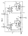
- valve unit G1 In figure 2 there is shown an embodiment of the valve unit G1 (the other units G2-G4 of Figure 1 have an analogous structure).
- valve unit of G1 comprises two pneumatically controlled pneumatic valves 10, 11.
- the pneumatic valve 10 has an inlet 10a through which the pressure coming from the brake control means BCU can be introduced into a lower chamber 10b beneath a membrane 10c capable of cooperating in the manner of a valve shutter, with a valve seat 10d of the outlet 10e of this valve.
- the chamber 10f above the membrane is capable of receiving a pneumatic control pressure through a control inlet 10g.
- valve 11 is structurally identical to the valve 10 and its parts have been indicated with the number 11 followed by the same letters utilised above to distinguish the parts of the valve 10.
- the inlet 10a of the valve 10 receives, in operation, a pressure coming from the brake control means BCU and intended for the brake cylinder BC1 of the axle 1.
- the pressure at the inlet 10a of the valve 10 may or may not lead to the brake cylinder BC1 depending on the position assumed by the membrane 10c which is controlled by the pneumatic pressure in the upper chamber 10f.
- valve 10 Associated with the valve 10 are two structurally identical solenoid control valves indicated 12 and 14, controlled by the unit A and the unit B respectively.
- the solenoid vales are two-way two-position valves with a return spring.
- the pneumatic valve 11 has its inlet 11a connected to the brake cylinder BC1 and to the outlet 10e of the valve 10.
- the outlet 11e of the valve 11 is a discharge-to-atmosphere outlet.
- Two electric pressure transducers 16 and 17 are conveniently disposed in such a way as to detect the pressure at the inlet 10a of the pneumatic valve 10 and, respectively, between the outlet 10e of the valve 10 and the inlet 11a of the valve 11 (or rather the pressure in the brake cylinder BC1).
Claims (3)
- Véhicule ferroviaire muni d'un système de freinage pneumatique, comprenant un appareil de contrôle des freins (BCA), auquel peuvent être reliées une pluralité d'unités de soupape électromagnétiques (G1-) pour le contrôle des cylindres de frein (BC1-BC4) associés aux roues/essieux (1-4) du véhicule, et un système de contrôle de freinage (A, B; BCA; G1-G4; S11-S42) avec des fonctions anti-dérapage et anti-blocage des roues; lesdites unités de soupape (G1-G4) pouvant être contrôlées par un moyen de contrôle (A, B) de manière à permettre, sélectivement, l'application d'une pression de freinage sur les cylindres de frein associés (BC1-BC4), le maintien de cette pression, et le relâchement de la pression desdits cylindres de frein (BC1-BC4);
caractérisé en ce que
au moins un premier et un second capteurs de vitesse angulaire (S1, S2 ; ... ; S41, S42) peuvent être associés à chaque essieu (1-4) du véhicule indépendamment l'un de l'autre ;
lesdites unités de soupape électromagnétiques (G1-G4) comprennent des soupapes de contrôle solénoïdes respectives (12-15) avec des première et seconde entrées de contrôle indépendantes (G11, G12) ; et
le moyen de contrôle (A, B) comprend
des première et seconde unités de contrôle électroniques indépendantes (A, B); les premiers capteurs de vitesse (S11; ... ; S41) de chaque essieu (1-4), ainsi que les premières unités d'entrée de contrôle (G11; ... ; G41) desdites unités de soupape (G1-G4) étant connectés à la première unité de contrôle (A); les seconds capteurs de vitesse (S12; ...; S42) et les secondes unités d'entrée de contrôle (G12; ...; G42) desdites unités de soupape (G1-G4) étant connectés seulement à la seconde unité de contrôle (B); lesdites unités de contrôle (A, B) étant prédisposées à transmettre de l'une à l'autre un signal d'état ou signal vital respectif (L1 ; L2) indicatif de sa condition de fonctionnement ;
la première unité (A) étant agencée pour effectuer une procédure anti-dérapage des roues ;
la seconde unité (B) étant agencée pour effectuer une procédure anti-blocage des roues lorsque le signal d'état (L1) qui lui est transmis par la première unité (A) indique que cette dernière fonctionne normalement et pour effectuer à la fois la procédure anti-blocage des roues et une procédure anti-dérapage des roues lorsque le signal d'état (L1) qui lui est transmis par la première unité (A) est indicatif d'un dysfonctionnement ou d'un état de panne de cette dernière. - Véhicule ferroviaire selon la revendication 1, dans lequel chaque unité de soupape (G1-G4) comprend
un premier bloc de soupapes de pression ou de soupapes pneumatiques (10) à contrôle pneumatique disposé entre l'appareil de contrôle des freins (BCA) et (au moins) un cylindre de frein associé (BC1) et une seconde soupape de décharge ou soupape pneumatique (11) à contrôle pneumatique reliée audit cylindre de frein (BC1) et dont la sortie est capable de se décharger dans l'atmosphère,
chacune desdites soupapes pneumatiques étant associée à une première et seconde soupapes solénoïde de contrôle respectives (12, 14 ; 12, 15) contrôlôes respectivement par les première et seconde unités électroniques (A, B). - Véhicule ferroviaire selon la revendication 2, dans lequel lesdites soupapes solénoïdes de contrôle (12, 14 ; 13, 15) sont du type bidirectionnel et à deux positions.
Priority Applications (2)
| Application Number | Priority Date | Filing Date | Title |
|---|---|---|---|
| DE602005000267T DE602005000267T3 (de) | 2004-03-17 | 2005-03-17 | Bremssteuersystem für Schienenfahrzeuge mit integriertem Antiblockier- und Antriebsschlupfregelsystem |
| PL05102092T PL1577185T5 (pl) | 2004-03-17 | 2005-03-17 | Hamulcowy układ sterujący do pojazdu kolejowego lub tramwajowego o funkcjach przeciwdziałania poślizgowi i blokowaniu kół |
Applications Claiming Priority (2)
| Application Number | Priority Date | Filing Date | Title |
|---|---|---|---|
| IT000179A ITTO20040179A1 (it) | 2004-03-17 | 2004-03-17 | Sistema di controllo della frenatura di un veicolo ferroviario o ferrotranviario con funzioni integrate di antipattinaggio e di antibloccaggio delle rotte |
| ITTO20040179 | 2004-03-17 |
Publications (3)
| Publication Number | Publication Date |
|---|---|
| EP1577185A1 EP1577185A1 (fr) | 2005-09-21 |
| EP1577185B1 EP1577185B1 (fr) | 2006-11-22 |
| EP1577185B2 true EP1577185B2 (fr) | 2013-07-31 |
Family
ID=34835623
Family Applications (1)
| Application Number | Title | Priority Date | Filing Date |
|---|---|---|---|
| EP05102092.3A Active EP1577185B2 (fr) | 2004-03-17 | 2005-03-17 | Système de contrôle de frein pour véhicule ferroviaire ou tramway avec un système antipatinage et un système antiblocage de roue integrés |
Country Status (7)
| Country | Link |
|---|---|
| US (1) | US7413265B2 (fr) |
| EP (1) | EP1577185B2 (fr) |
| AT (1) | ATE345959T1 (fr) |
| DE (1) | DE602005000267T3 (fr) |
| ES (1) | ES2275257T5 (fr) |
| IT (1) | ITTO20040179A1 (fr) |
| PL (1) | PL1577185T5 (fr) |
Families Citing this family (10)
| Publication number | Priority date | Publication date | Assignee | Title |
|---|---|---|---|---|
| US7374252B2 (en) * | 2006-03-16 | 2008-05-20 | Wabtec Holding Corporation | Wheel slip brake assurance module |
| DE102008032715B4 (de) * | 2008-07-11 | 2012-03-08 | Knorr-Bremse Systeme für Schienenfahrzeuge GmbH | Elektropneumatische Bremseinrichtung eines Schienenfahrzeuges |
| DE102008052906A1 (de) * | 2008-10-23 | 2010-05-20 | Siemens Aktiengesellschaft | Verfahren zur Durchführung einer Rollprobe bei einem Schienenfahrzeug und Steuerungseinrichtung dafür |
| US8682559B2 (en) * | 2010-12-14 | 2014-03-25 | Nxp B.V. | Distributed electrical brake circuit and system |
| CN105612089B (zh) * | 2013-10-17 | 2018-06-19 | 罗伯特·博世有限公司 | 确认汽车的安全功能的方法 |
| DE102014220441A1 (de) * | 2014-01-16 | 2015-07-16 | Continental Teves Ag & Co. Ohg | Bremsanlage für Fahrzeuge |
| DE102014107402B4 (de) * | 2014-05-26 | 2021-11-04 | Knorr-Bremse Systeme für Schienenfahrzeuge GmbH | Schienenfahrzeugbremssystem mit einer Konditionierungseinrichtung, Konditionierungseinrichtung und Verfahren zum Betreiben einer Konditionierungseinrichtung |
| WO2018117236A1 (fr) * | 2016-12-21 | 2018-06-28 | 株式会社アドヴィックス | Dispositif de freinage de véhicule |
| GB2565846B (en) | 2017-08-25 | 2022-02-09 | Haldex Brake Prod Ab | Braking system |
| EA202192562A1 (ru) | 2019-04-30 | 2022-03-01 | Файвеле Транспорт Италиа С.П.А. | Система контроля вращения по меньшей мере одной оси для железнодорожного транспортного средства или поезда |
Citations (12)
| Publication number | Priority date | Publication date | Assignee | Title |
|---|---|---|---|---|
| DE2530609A1 (de) † | 1975-07-09 | 1977-01-27 | Knorr Bremse Gmbh | Bremskraftregelkreis |
| US4085979A (en) † | 1976-04-01 | 1978-04-25 | Teldix Gmbh | Testing arrangement for antilocking control system with two identical antilocking control units |
| US4400792A (en) † | 1980-01-30 | 1983-08-23 | Siemens Aktiengesellschaft | Dual-channel data processing system for railroad safety purposes |
| US5001641A (en) † | 1987-03-20 | 1991-03-19 | Sumitomo Electric Industries, Ltd. | Multiple control circuit |
| US5193888A (en) † | 1990-02-22 | 1993-03-16 | Mazda Motor Corporation | Slip control system for motor vehicle |
| US5548601A (en) † | 1992-12-02 | 1996-08-20 | Mazda Motor Corporation | Apparatus and method for diagnosing failures in control system |
| US5718486A (en) † | 1993-12-17 | 1998-02-17 | Knorr-Bremse Systeme Fur Nutzfahrzeuge Gmbh | Electropneumatic brakes system for motor vehicles |
| US5826954A (en) † | 1995-11-08 | 1998-10-27 | Robert Bosch Gmbh | Method and apparatus for controlling the brake system of a vehicle |
| US5895434A (en) † | 1994-11-02 | 1999-04-20 | Itt Manufacturing Enterprises Inc. | Microprocessor arrangement for a vehicle control system |
| US6173229B1 (en) † | 1996-08-02 | 2001-01-09 | Continental Teves Ag & Co. Ohg | Microprocessor arrangement for a vehicle-control system |
| US6209966B1 (en) † | 1997-03-05 | 2001-04-03 | Mannesmann Rexroth Ag | Electrically controlled braking system for a wheeled vehicle |
| US20040046442A1 (en) † | 1998-10-23 | 2004-03-11 | Knorr-Bremse System Fur Schienenfahrzeuge Gmbh | Brake system for railway vehicles |
Family Cites Families (2)
| Publication number | Priority date | Publication date | Assignee | Title |
|---|---|---|---|---|
| AT367817B (de) * | 1980-10-08 | 1982-08-10 | Plasser Bahnbaumasch Franz | Fahrbare gleisbaumaschine mit schienenfahrwerken und schrittweiser arbeitsvorfahrt |
| DE4227084B4 (de) | 1992-08-17 | 2004-03-25 | Knorr-Bremse Systeme für Nutzfahrzeuge GmbH | Druckregelmodul einer Druckluft-Fahrzeugbremsanlage |
-
2004
- 2004-03-17 IT IT000179A patent/ITTO20040179A1/it unknown
-
2005
- 2005-03-16 US US11/080,499 patent/US7413265B2/en active Active
- 2005-03-17 PL PL05102092T patent/PL1577185T5/pl unknown
- 2005-03-17 ES ES05102092T patent/ES2275257T5/es active Active
- 2005-03-17 AT AT05102092T patent/ATE345959T1/de not_active IP Right Cessation
- 2005-03-17 DE DE602005000267T patent/DE602005000267T3/de active Active
- 2005-03-17 EP EP05102092.3A patent/EP1577185B2/fr active Active
Patent Citations (12)
| Publication number | Priority date | Publication date | Assignee | Title |
|---|---|---|---|---|
| DE2530609A1 (de) † | 1975-07-09 | 1977-01-27 | Knorr Bremse Gmbh | Bremskraftregelkreis |
| US4085979A (en) † | 1976-04-01 | 1978-04-25 | Teldix Gmbh | Testing arrangement for antilocking control system with two identical antilocking control units |
| US4400792A (en) † | 1980-01-30 | 1983-08-23 | Siemens Aktiengesellschaft | Dual-channel data processing system for railroad safety purposes |
| US5001641A (en) † | 1987-03-20 | 1991-03-19 | Sumitomo Electric Industries, Ltd. | Multiple control circuit |
| US5193888A (en) † | 1990-02-22 | 1993-03-16 | Mazda Motor Corporation | Slip control system for motor vehicle |
| US5548601A (en) † | 1992-12-02 | 1996-08-20 | Mazda Motor Corporation | Apparatus and method for diagnosing failures in control system |
| US5718486A (en) † | 1993-12-17 | 1998-02-17 | Knorr-Bremse Systeme Fur Nutzfahrzeuge Gmbh | Electropneumatic brakes system for motor vehicles |
| US5895434A (en) † | 1994-11-02 | 1999-04-20 | Itt Manufacturing Enterprises Inc. | Microprocessor arrangement for a vehicle control system |
| US5826954A (en) † | 1995-11-08 | 1998-10-27 | Robert Bosch Gmbh | Method and apparatus for controlling the brake system of a vehicle |
| US6173229B1 (en) † | 1996-08-02 | 2001-01-09 | Continental Teves Ag & Co. Ohg | Microprocessor arrangement for a vehicle-control system |
| US6209966B1 (en) † | 1997-03-05 | 2001-04-03 | Mannesmann Rexroth Ag | Electrically controlled braking system for a wheeled vehicle |
| US20040046442A1 (en) † | 1998-10-23 | 2004-03-11 | Knorr-Bremse System Fur Schienenfahrzeuge Gmbh | Brake system for railway vehicles |
Also Published As
| Publication number | Publication date |
|---|---|
| US20050212354A1 (en) | 2005-09-29 |
| US7413265B2 (en) | 2008-08-19 |
| PL1577185T5 (pl) | 2014-03-31 |
| ES2275257T5 (es) | 2013-12-05 |
| ITTO20040179A1 (it) | 2004-06-17 |
| EP1577185B1 (fr) | 2006-11-22 |
| EP1577185A1 (fr) | 2005-09-21 |
| DE602005000267T3 (de) | 2013-12-24 |
| ATE345959T1 (de) | 2006-12-15 |
| DE602005000267T2 (de) | 2007-04-05 |
| PL1577185T3 (pl) | 2007-02-28 |
| ES2275257T3 (es) | 2007-06-01 |
| DE602005000267D1 (de) | 2007-01-04 |
Similar Documents
| Publication | Publication Date | Title |
|---|---|---|
| EP1577185B2 (fr) | Système de contrôle de frein pour véhicule ferroviaire ou tramway avec un système antipatinage et un système antiblocage de roue integrés | |
| US11932229B2 (en) | Electronically controllable braking system having two fall-back levels | |
| CN101939199B (zh) | 用于汽车的驻车制动器以及用于运行驻车制动器的方法 | |
| JP3288493B2 (ja) | 圧縮空気ブレーキ装置に用いられる圧力制御モジュール | |
| CN102470848B (zh) | 用于车辆制动设备的控制器以及具有该控制器的制动设备 | |
| CN108883755A (zh) | 商用车辆中的能电子控制的气动制动系统和用于电子控制气动制动系统的方法 | |
| EP0855319B1 (fr) | Unité de commande d'une conduite de frein ferroviaire | |
| CN101495350A (zh) | 用于汽车的制动设备 | |
| CN102325678A (zh) | 具有气动回路分开的压力调节通道的电气动压力调节模块 | |
| CZ281062B6 (cs) | Elektronický brzdový systém pro silniční vozidla | |
| CN104428180A (zh) | 用于轨道车辆制动器的控制阀装置 | |
| CN103732461A (zh) | 具有磁轨制动装置的制动设备 | |
| US20060152075A1 (en) | Pressure regulator module for a motor vehicle pneumatic braking system | |
| US20220185251A1 (en) | Electropneumatic brake system for a utility vehicle | |
| EP3328698A1 (fr) | Appareil électropneumatique pour la commande de freinage d'un véhicule ferroviaire | |
| CN101680501B (zh) | 用于车辆手动变速器的离合器调整装置及相应的控制方法 | |
| AU2006213971B2 (en) | A braking control system for a railway or tramway vehicle with integrated anti-slip and anti-lock functions for the wheels | |
| US20120203439A1 (en) | Method for controlling a vehicle having only a braked rear axle and brake slip control | |
| WO2000000360A1 (fr) | Ensemble perfectionne de commande de traction et de suspension | |
| CN210310369U (zh) | 一种无轨电车制动系统及无轨电车 | |
| CN113365889A (zh) | 具有针对单独车轮的abs控制部的驻车制动器设施 | |
| CN107206994A (zh) | 车辆的具有在制动缓解时的噪声降低的电子气动式行车制动装置及其控制方法 | |
| CA2313441C (fr) | Systeme de commande et de communication pour trains | |
| US5634700A (en) | Slip-controlled brake system for commercial vehicles | |
| CN210000310U (zh) | 一种牵引车驻车装置 |
Legal Events
| Date | Code | Title | Description |
|---|---|---|---|
| PUAI | Public reference made under article 153(3) epc to a published international application that has entered the european phase |
Free format text: ORIGINAL CODE: 0009012 |
|
| AK | Designated contracting states |
Kind code of ref document: A1 Designated state(s): AT BE BG CH CY CZ DE DK EE ES FI FR GB GR HU IE IS IT LI LT LU MC NL PL PT RO SE SI SK TR |
|
| AX | Request for extension of the european patent |
Extension state: AL BA HR LV MK YU |
|
| 17P | Request for examination filed |
Effective date: 20060310 |
|
| AKX | Designation fees paid |
Designated state(s): AT BE BG CH CY CZ DE DK EE ES FI FR GB GR HU IE IS IT LI LT LU MC NL PL PT RO SE SI SK TR |
|
| GRAP | Despatch of communication of intention to grant a patent |
Free format text: ORIGINAL CODE: EPIDOSNIGR1 |
|
| RAP1 | Party data changed (applicant data changed or rights of an application transferred) |
Owner name: FAIVELEY TRANSPORT ITALIA S.P.A. |
|
| GRAS | Grant fee paid |
Free format text: ORIGINAL CODE: EPIDOSNIGR3 |
|
| GRAA | (expected) grant |
Free format text: ORIGINAL CODE: 0009210 |
|
| AK | Designated contracting states |
Kind code of ref document: B1 Designated state(s): AT BE BG CH CY CZ DE DK EE ES FI FR GB GR HU IE IS IT LI LT LU MC NL PL PT RO SE SI SK TR |
|
| PG25 | Lapsed in a contracting state [announced via postgrant information from national office to epo] |
Ref country code: IT Free format text: LAPSE BECAUSE OF FAILURE TO SUBMIT A TRANSLATION OF THE DESCRIPTION OR TO PAY THE FEE WITHIN THE PRESCRIBED TIME-LIMIT;WARNING: LAPSES OF ITALIAN PATENTS WITH EFFECTIVE DATE BEFORE 2007 MAY HAVE OCCURRED AT ANY TIME BEFORE 2007. THE CORRECT EFFECTIVE DATE MAY BE DIFFERENT FROM THE ONE RECORDED. Effective date: 20061122 Ref country code: SK Free format text: LAPSE BECAUSE OF FAILURE TO SUBMIT A TRANSLATION OF THE DESCRIPTION OR TO PAY THE FEE WITHIN THE PRESCRIBED TIME-LIMIT Effective date: 20061122 Ref country code: SI Free format text: LAPSE BECAUSE OF FAILURE TO SUBMIT A TRANSLATION OF THE DESCRIPTION OR TO PAY THE FEE WITHIN THE PRESCRIBED TIME-LIMIT Effective date: 20061122 Ref country code: BE Free format text: LAPSE BECAUSE OF FAILURE TO SUBMIT A TRANSLATION OF THE DESCRIPTION OR TO PAY THE FEE WITHIN THE PRESCRIBED TIME-LIMIT Effective date: 20061122 Ref country code: AT Free format text: LAPSE BECAUSE OF FAILURE TO SUBMIT A TRANSLATION OF THE DESCRIPTION OR TO PAY THE FEE WITHIN THE PRESCRIBED TIME-LIMIT Effective date: 20061122 Ref country code: CH Free format text: LAPSE BECAUSE OF FAILURE TO SUBMIT A TRANSLATION OF THE DESCRIPTION OR TO PAY THE FEE WITHIN THE PRESCRIBED TIME-LIMIT Effective date: 20061122 Ref country code: LT Free format text: LAPSE BECAUSE OF FAILURE TO SUBMIT A TRANSLATION OF THE DESCRIPTION OR TO PAY THE FEE WITHIN THE PRESCRIBED TIME-LIMIT Effective date: 20061122 Ref country code: LI Free format text: LAPSE BECAUSE OF FAILURE TO SUBMIT A TRANSLATION OF THE DESCRIPTION OR TO PAY THE FEE WITHIN THE PRESCRIBED TIME-LIMIT Effective date: 20061122 Ref country code: NL Free format text: LAPSE BECAUSE OF FAILURE TO SUBMIT A TRANSLATION OF THE DESCRIPTION OR TO PAY THE FEE WITHIN THE PRESCRIBED TIME-LIMIT Effective date: 20061122 Ref country code: CZ Free format text: LAPSE BECAUSE OF FAILURE TO SUBMIT A TRANSLATION OF THE DESCRIPTION OR TO PAY THE FEE WITHIN THE PRESCRIBED TIME-LIMIT Effective date: 20061122 Ref country code: FI Free format text: LAPSE BECAUSE OF FAILURE TO SUBMIT A TRANSLATION OF THE DESCRIPTION OR TO PAY THE FEE WITHIN THE PRESCRIBED TIME-LIMIT Effective date: 20061122 |
|
| REG | Reference to a national code |
Ref country code: GB Ref legal event code: FG4D |
|
| REG | Reference to a national code |
Ref country code: CH Ref legal event code: EP |
|
| REG | Reference to a national code |
Ref country code: IE Ref legal event code: FG4D |
|
| REF | Corresponds to: |
Ref document number: 602005000267 Country of ref document: DE Date of ref document: 20070104 Kind code of ref document: P |
|
| REG | Reference to a national code |
Ref country code: RO Ref legal event code: EPE |
|
| PG25 | Lapsed in a contracting state [announced via postgrant information from national office to epo] |
Ref country code: BG Free format text: LAPSE BECAUSE OF FAILURE TO SUBMIT A TRANSLATION OF THE DESCRIPTION OR TO PAY THE FEE WITHIN THE PRESCRIBED TIME-LIMIT Effective date: 20070222 Ref country code: DK Free format text: LAPSE BECAUSE OF FAILURE TO SUBMIT A TRANSLATION OF THE DESCRIPTION OR TO PAY THE FEE WITHIN THE PRESCRIBED TIME-LIMIT Effective date: 20070222 |
|
| REG | Reference to a national code |
Ref country code: PL Ref legal event code: T3 |
|
| REG | Reference to a national code |
Ref country code: SE Ref legal event code: TRGR |
|
| PG25 | Lapsed in a contracting state [announced via postgrant information from national office to epo] |
Ref country code: IS Free format text: LAPSE BECAUSE OF FAILURE TO SUBMIT A TRANSLATION OF THE DESCRIPTION OR TO PAY THE FEE WITHIN THE PRESCRIBED TIME-LIMIT Effective date: 20070322 |
|
| PG25 | Lapsed in a contracting state [announced via postgrant information from national office to epo] |
Ref country code: PT Free format text: LAPSE BECAUSE OF FAILURE TO SUBMIT A TRANSLATION OF THE DESCRIPTION OR TO PAY THE FEE WITHIN THE PRESCRIBED TIME-LIMIT Effective date: 20070423 |
|
| NLV1 | Nl: lapsed or annulled due to failure to fulfill the requirements of art. 29p and 29m of the patents act | ||
| ET | Fr: translation filed | ||
| REG | Reference to a national code |
Ref country code: ES Ref legal event code: FG2A Ref document number: 2275257 Country of ref document: ES Kind code of ref document: T3 |
|
| REG | Reference to a national code |
Ref country code: CH Ref legal event code: PL |
|
| PLBI | Opposition filed |
Free format text: ORIGINAL CODE: 0009260 |
|
| PLAX | Notice of opposition and request to file observation + time limit sent |
Free format text: ORIGINAL CODE: EPIDOSNOBS2 |
|
| 26 | Opposition filed |
Opponent name: KNORR-BREMSE SYSTEME FUER SCHIENENFAHRZEUGE GMBH Effective date: 20070821 |
|
| PLAF | Information modified related to communication of a notice of opposition and request to file observations + time limit |
Free format text: ORIGINAL CODE: EPIDOSCOBS2 |
|
| PG25 | Lapsed in a contracting state [announced via postgrant information from national office to epo] |
Ref country code: MC Free format text: LAPSE BECAUSE OF NON-PAYMENT OF DUE FEES Effective date: 20070331 Ref country code: IE Free format text: LAPSE BECAUSE OF NON-PAYMENT OF DUE FEES Effective date: 20070320 |
|
| PLBB | Reply of patent proprietor to notice(s) of opposition received |
Free format text: ORIGINAL CODE: EPIDOSNOBS3 |
|
| PG25 | Lapsed in a contracting state [announced via postgrant information from national office to epo] |
Ref country code: GR Free format text: LAPSE BECAUSE OF FAILURE TO SUBMIT A TRANSLATION OF THE DESCRIPTION OR TO PAY THE FEE WITHIN THE PRESCRIBED TIME-LIMIT Effective date: 20070223 |
|
| PG25 | Lapsed in a contracting state [announced via postgrant information from national office to epo] |
Ref country code: EE Free format text: LAPSE BECAUSE OF FAILURE TO SUBMIT A TRANSLATION OF THE DESCRIPTION OR TO PAY THE FEE WITHIN THE PRESCRIBED TIME-LIMIT Effective date: 20061122 |
|
| PG25 | Lapsed in a contracting state [announced via postgrant information from national office to epo] |
Ref country code: CY Free format text: LAPSE BECAUSE OF FAILURE TO SUBMIT A TRANSLATION OF THE DESCRIPTION OR TO PAY THE FEE WITHIN THE PRESCRIBED TIME-LIMIT Effective date: 20061122 Ref country code: LU Free format text: LAPSE BECAUSE OF NON-PAYMENT OF DUE FEES Effective date: 20070317 |
|
| PG25 | Lapsed in a contracting state [announced via postgrant information from national office to epo] |
Ref country code: TR Free format text: LAPSE BECAUSE OF FAILURE TO SUBMIT A TRANSLATION OF THE DESCRIPTION OR TO PAY THE FEE WITHIN THE PRESCRIBED TIME-LIMIT Effective date: 20061122 Ref country code: HU Free format text: LAPSE BECAUSE OF FAILURE TO SUBMIT A TRANSLATION OF THE DESCRIPTION OR TO PAY THE FEE WITHIN THE PRESCRIBED TIME-LIMIT Effective date: 20070523 |
|
| APBM | Appeal reference recorded |
Free format text: ORIGINAL CODE: EPIDOSNREFNO |
|
| APBP | Date of receipt of notice of appeal recorded |
Free format text: ORIGINAL CODE: EPIDOSNNOA2O |
|
| APAH | Appeal reference modified |
Free format text: ORIGINAL CODE: EPIDOSCREFNO |
|
| APBQ | Date of receipt of statement of grounds of appeal recorded |
Free format text: ORIGINAL CODE: EPIDOSNNOA3O |
|
| APBU | Appeal procedure closed |
Free format text: ORIGINAL CODE: EPIDOSNNOA9O |
|
| PUAH | Patent maintained in amended form |
Free format text: ORIGINAL CODE: 0009272 |
|
| STAA | Information on the status of an ep patent application or granted ep patent |
Free format text: STATUS: PATENT MAINTAINED AS AMENDED |
|
| 27A | Patent maintained in amended form |
Effective date: 20130731 |
|
| AK | Designated contracting states |
Kind code of ref document: B2 Designated state(s): AT BE BG CH CY CZ DE DK EE ES FI FR GB GR HU IE IS IT LI LT LU MC NL PL PT RO SE SI SK TR |
|
| REG | Reference to a national code |
Ref country code: DE Ref legal event code: R102 Ref document number: 602005000267 Country of ref document: DE |
|
| REG | Reference to a national code |
Ref country code: DE Ref legal event code: R102 Ref document number: 602005000267 Country of ref document: DE Effective date: 20130731 |
|
| REG | Reference to a national code |
Ref country code: SE Ref legal event code: RPEO |
|
| REG | Reference to a national code |
Ref country code: ES Ref legal event code: DC2A Ref document number: 2275257 Country of ref document: ES Kind code of ref document: T5 Effective date: 20131205 |
|
| PGFP | Annual fee paid to national office [announced via postgrant information from national office to epo] |
Ref country code: RO Payment date: 20150804 Year of fee payment: 11 Ref country code: GB Payment date: 20150730 Year of fee payment: 11 |
|
| PGFP | Annual fee paid to national office [announced via postgrant information from national office to epo] |
Ref country code: SE Payment date: 20150731 Year of fee payment: 11 Ref country code: PL Payment date: 20150730 Year of fee payment: 11 |
|
| REG | Reference to a national code |
Ref country code: FR Ref legal event code: PLFP Year of fee payment: 12 |
|
| REG | Reference to a national code |
Ref country code: SE Ref legal event code: EUG |
|
| GBPC | Gb: european patent ceased through non-payment of renewal fee |
Effective date: 20160317 |
|
| PG25 | Lapsed in a contracting state [announced via postgrant information from national office to epo] |
Ref country code: RO Free format text: LAPSE BECAUSE OF NON-PAYMENT OF DUE FEES Effective date: 20160317 Ref country code: SE Free format text: LAPSE BECAUSE OF NON-PAYMENT OF DUE FEES Effective date: 20160318 |
|
| PG25 | Lapsed in a contracting state [announced via postgrant information from national office to epo] |
Ref country code: GB Free format text: LAPSE BECAUSE OF NON-PAYMENT OF DUE FEES Effective date: 20160317 |
|
| REG | Reference to a national code |
Ref country code: FR Ref legal event code: PLFP Year of fee payment: 13 |
|
| PG25 | Lapsed in a contracting state [announced via postgrant information from national office to epo] |
Ref country code: PL Free format text: LAPSE BECAUSE OF NON-PAYMENT OF DUE FEES Effective date: 20160317 |
|
| REG | Reference to a national code |
Ref country code: FR Ref legal event code: PLFP Year of fee payment: 14 |
|
| PGFP | Annual fee paid to national office [announced via postgrant information from national office to epo] |
Ref country code: FR Payment date: 20190213 Year of fee payment: 15 |
|
| PGFP | Annual fee paid to national office [announced via postgrant information from national office to epo] |
Ref country code: ES Payment date: 20190401 Year of fee payment: 15 |
|
| PGFP | Annual fee paid to national office [announced via postgrant information from national office to epo] |
Ref country code: DE Payment date: 20200310 Year of fee payment: 16 |
|
| PG25 | Lapsed in a contracting state [announced via postgrant information from national office to epo] |
Ref country code: FR Free format text: LAPSE BECAUSE OF NON-PAYMENT OF DUE FEES Effective date: 20200331 |
|
| REG | Reference to a national code |
Ref country code: ES Ref legal event code: FD2A Effective date: 20210730 |
|
| REG | Reference to a national code |
Ref country code: DE Ref legal event code: R119 Ref document number: 602005000267 Country of ref document: DE |
|
| PG25 | Lapsed in a contracting state [announced via postgrant information from national office to epo] |
Ref country code: ES Free format text: LAPSE BECAUSE OF NON-PAYMENT OF DUE FEES Effective date: 20200318 |
|
| PG25 | Lapsed in a contracting state [announced via postgrant information from national office to epo] |
Ref country code: DE Free format text: LAPSE BECAUSE OF NON-PAYMENT OF DUE FEES Effective date: 20211001 |