EP1577094A1 - Reinigungsvorrichtung für einen Zylinder in einer Verarbeitungsmaschine - Google Patents
Reinigungsvorrichtung für einen Zylinder in einer Verarbeitungsmaschine Download PDFInfo
- Publication number
- EP1577094A1 EP1577094A1 EP05004776A EP05004776A EP1577094A1 EP 1577094 A1 EP1577094 A1 EP 1577094A1 EP 05004776 A EP05004776 A EP 05004776A EP 05004776 A EP05004776 A EP 05004776A EP 1577094 A1 EP1577094 A1 EP 1577094A1
- Authority
- EP
- European Patent Office
- Prior art keywords
- cylinder
- brush
- bristle
- cleaning device
- roller
- Prior art date
- Legal status (The legal status is an assumption and is not a legal conclusion. Google has not performed a legal analysis and makes no representation as to the accuracy of the status listed.)
- Withdrawn
Links
- 238000004140 cleaning Methods 0.000 title claims abstract description 50
- 238000012545 processing Methods 0.000 title claims description 6
- 241000904500 Oxyspora paniculata Species 0.000 claims abstract description 19
- 239000007788 liquid Substances 0.000 claims description 7
- 239000000565 sealant Substances 0.000 claims description 7
- 238000003776 cleavage reaction Methods 0.000 claims description 6
- 230000007017 scission Effects 0.000 claims description 6
- 239000011248 coating agent Substances 0.000 claims description 2
- 238000000576 coating method Methods 0.000 claims description 2
- 239000007921 spray Substances 0.000 description 14
- 239000012530 fluid Substances 0.000 description 7
- 238000005406 washing Methods 0.000 description 4
- 230000000694 effects Effects 0.000 description 3
- 229920000728 polyester Polymers 0.000 description 3
- 238000011144 upstream manufacturing Methods 0.000 description 3
- 239000004952 Polyamide Substances 0.000 description 2
- 230000001680 brushing effect Effects 0.000 description 2
- 238000011161 development Methods 0.000 description 2
- 230000018109 developmental process Effects 0.000 description 2
- 239000000463 material Substances 0.000 description 2
- 239000000203 mixture Substances 0.000 description 2
- 229920002647 polyamide Polymers 0.000 description 2
- VYZAMTAEIAYCRO-UHFFFAOYSA-N Chromium Chemical compound [Cr] VYZAMTAEIAYCRO-UHFFFAOYSA-N 0.000 description 1
- ZOKXTWBITQBERF-UHFFFAOYSA-N Molybdenum Chemical compound [Mo] ZOKXTWBITQBERF-UHFFFAOYSA-N 0.000 description 1
- 239000000853 adhesive Substances 0.000 description 1
- 230000001070 adhesive effect Effects 0.000 description 1
- 229910052782 aluminium Inorganic materials 0.000 description 1
- XAGFODPZIPBFFR-UHFFFAOYSA-N aluminium Chemical compound [Al] XAGFODPZIPBFFR-UHFFFAOYSA-N 0.000 description 1
- 239000000919 ceramic Substances 0.000 description 1
- 229910052804 chromium Inorganic materials 0.000 description 1
- 239000011651 chromium Substances 0.000 description 1
- 239000010941 cobalt Substances 0.000 description 1
- 229910017052 cobalt Inorganic materials 0.000 description 1
- GUTLYIVDDKVIGB-UHFFFAOYSA-N cobalt atom Chemical compound [Co] GUTLYIVDDKVIGB-UHFFFAOYSA-N 0.000 description 1
- 239000004922 lacquer Substances 0.000 description 1
- 229910052751 metal Inorganic materials 0.000 description 1
- 239000002184 metal Substances 0.000 description 1
- 238000000034 method Methods 0.000 description 1
- 210000000110 microvilli Anatomy 0.000 description 1
- 229910052750 molybdenum Inorganic materials 0.000 description 1
- 239000011733 molybdenum Substances 0.000 description 1
- 238000010422 painting Methods 0.000 description 1
- 230000035515 penetration Effects 0.000 description 1
- 239000004033 plastic Substances 0.000 description 1
- 239000000758 substrate Substances 0.000 description 1
- 238000012549 training Methods 0.000 description 1
- 238000012546 transfer Methods 0.000 description 1
- UONOETXJSWQNOL-UHFFFAOYSA-N tungsten carbide Chemical compound [W+]#[C-] UONOETXJSWQNOL-UHFFFAOYSA-N 0.000 description 1
- 239000002966 varnish Substances 0.000 description 1
- XLYOFNOQVPJJNP-UHFFFAOYSA-N water Substances O XLYOFNOQVPJJNP-UHFFFAOYSA-N 0.000 description 1
Images


Classifications
-
- B—PERFORMING OPERATIONS; TRANSPORTING
- B41—PRINTING; LINING MACHINES; TYPEWRITERS; STAMPS
- B41F—PRINTING MACHINES OR PRESSES
- B41F35/00—Cleaning arrangements or devices
-
- B—PERFORMING OPERATIONS; TRANSPORTING
- B41—PRINTING; LINING MACHINES; TYPEWRITERS; STAMPS
- B41P—INDEXING SCHEME RELATING TO PRINTING, LINING MACHINES, TYPEWRITERS, AND TO STAMPS
- B41P2235/00—Cleaning
- B41P2235/10—Cleaning characterised by the methods or devices
- B41P2235/20—Wiping devices
- B41P2235/23—Brushes
Definitions
- the invention relates to a cleaning device for a cylinder in one Processing machine, preferably a printing press or Painting machine, according to the preamble of claim 1, 2 and 3.
- Die Cleaning device has a provided with a brush trim Washing roller (brush roller) and is preferred for cleaning the lateral surface a cylinder or for cleaning a fixed on a cylinder printing plate in can be used such a processing machine.
- a cleaning device of this type is known from DE 200 08 043 U1.
- the Device is with a rotatably driven cleaning element receiving housing formed with a drain, which is a one Having cylinder facing opening.
- the housing still has at least two separate supply lines for different cleaning fluids on, each supply line line side with its own reservoir and is coupled with separate spray tubes in the housing.
- the cleaning element is preferably a drivable, provided with a brush stocking washing roller (Brush roller), which is constantly engaged with a doctor element.
- the invention is based on the object, a cleaning device of to create the aforementioned type, in particular in the cleaning of a sensitive surface formed by elevations and depressions a cylinder allows a gentle cleaning and an increased Achieved cleaning effect.
- the elevators close metallic or ceramic plates with such Surface profiles. Furthermore, if necessary, the surface profiles on the Cylinder shell surfaces or the elevators with a relative wear-sensitive sealant coated.
- the printing plates are preferred Flexographic printing forms (high-pressure forms) or blankets (full-surface or specially cut out), which on a forme cylinder or a Blanket cylinder can be arranged detachably.
- a second advantage results from the fact that by the special training of the Bürstenbesatzes the brush roller a noticeably increased cleaning effect on cylinder to be cleaned, the elevator, the blanket or the flexographic printing plate is achievable.
- a third advantage is that the brush roller by the special Forming the brushing the relevant, especially the sensitive Surface profile gently cleans, so that the surface to be cleaned one noticeably reduced wear.
- the brush roller is suitable in particular for cleaning with a wear-sensitive sealant coated surface profiles on cylinders or their elevators, but also for sensitive flexographic printing plates or recessed blankets, in which gently the relief depths and flanks of the printing plate can be cleaned.
- the cleaning device or the Brush roller in the cylinder channel passage preferably from the Cylinder surface off and then back to this can be adjusted. For a transport of cleaning fluid in the cylinder channel is avoidable.
- the brush roller in relation to the direction of rotation of the to be cleaned cylinder with alternating directions of rotation within a Washing sequence is driven.
- the elevations, depressions or Flanks of the surface profile comprehensively cleanable.
- the Brush roller additionally changeable in the axial direction drivable.
- the brush stocking over the width of Brush roll (in the axial direction) a brush trim with an outer and an inner diameter. Due to the different diameters of the Brushing is an improved penetration of the bristles in the wells and an improved cleaning effect on the flanks or the elevations of the respective surface profile feasible.
- the cleaning device shown in Figure 1 is on a cylinder 1, Preferably, a sheet guiding cylinder or a forme cylinder a Printing press or varnishing machine, arranged adjacent.
- the Cleaning device has a housing 2 of approximately rectangular Cross-section extending over the entire width of the cylinder 1.
- the Housing 2 consists of an upper housing part and a detachable thereto attached lower housing part with a drain disposed thereon 11 for contaminated cleaning fluid.
- the housing 2 has one of the cleaning lateral surface (or printing plate) of the cylinder 1 facing opening on, through which a rotatably mounted in the housing 2 brush roller 3 as Cleaning element protrudes so far that they are in the shown in Figure 1 Anstellposition with the cylinder 1 is in contact.
- a first spray tube 4 with an upstream first supply line 5 for a first cleaning fluid, a second spray tube 6 with an upstream second supply line 7 for a second cleaning fluid and a third spray tube 8 with an upstream third supply line 9 extend parallel to the brush roller 3 in the housing 2 for a third cleaning liquid, in particular for water.
- the spray pipes 4, 6, 8 have a plurality of small openings or nozzles which are distributed at regular intervals from one another over the entire length of the spray pipes 4, 6, 8.
- the spray tubes 4, 6, 8 are adjacent to the upper portion of the brush roller 3 and are located at a distance therefrom.
- individual nozzles can be arranged, which are coupled to the respective supply line 5, 7, 9 line side.
- On the housing 2 a further consisting of a cylindrical rod doctor blade 10 is arranged, which is preferably in continuous engagement with a brush attachment 13 of the brush roller 3.
- the first supply line 5, from the second spray pipe 6 leads the second supply line 7 and the third spray tube 8 leads the third Supply line 9 to a trained as 3/3-way valve; with a Machine control coupled valve block, which consists of three from each other separate reservoirs on preferably three separate pumps the Cleaning fluids are optionally supplied.
- the brush roller 3 mounted in the housing 2 as a cleaning element has a roller core 12, on which the brush attachment 13 is preferably arranged concentrically and concentrically in the axial direction.
- the brush stocking 13 (over the roll width) of the same outer diameter D 1 and preferably ground, so that a good concentricity of the brush roller 3 and a uniform cleaning result is guaranteed.
- this brush stocking 13 is spiral and in a further embodiment of the brush stocking 13 is tuft-shaped (see Fig. 2) arranged on the roll core 12.
- the brush stocking 13 is exemplified by a tuft of bristles 14 shown.
- the brush stocking 13 is characterized by a plurality of individual bristles 14 formed, which are fixedly arranged end on the roller core 12 and preferred radially have an equal length.
- every single bristle is 14 finely split (spliced) and thus has a plurality of bristle tips 15.
- each single bristle 14 has radially end from a cleavage point 16 at least two Bristle tips 15, which reduced in relation to the strength of a bristle 14 Bristle tip thicknesses have.
- more than at least two bristle tips 15 can be generated.
- the preferred splice depth length of the bristle tips 15 from the cleavage site 16 to the free end (diameter D 1 ) is about 3 to 8 mm for each bristle 14.
- the preferred single bristle tip thickness is about 0.10 to 0.30 mm per Bristle 14.
- the preferred length (from roll core 12 to diameter D) of bristles 14, including bristle tips 15, is about 10 to 35 mm per bristle 14.
- the brush stocking 13 preferably has bristles 14 (with bristle tips 15) Polyamide and / or polyester or contains at least such materials.
- a mixture of polyamide and polyester e.g. With in each case a share of 50%, can be used as a brush stocking 13.
- Each Bristle 14 is smooth or wavy executable.
- the brush attachment 13 is made uniform bristles 14, for example, smooth bristles 14 formed. Alternatively it is as well a mixture of smooth and wavy bristles 14 can be used.
- the brush roller 3 formed in this way is rotationally preferably alternating can be driven, additionally driven in an alternating axial manner if required.
- the drives are preferably coupled to the machine control.
- the one in a washing sequence on the cylinder 1 employed brush roller 3 is preferably a function of Passage of a cylinder channel from the cylinder 1 off and then back to the cylinder 1 adjustable.
- the brush roller 3 a cylinder 1 on / off associated, which is a flexible high-pressure mold, preferably a flexo / flexo varnish, or a blanket, including one recessed blanket, wears.
- a cylinder 1 is preferred as formed a blanket / form cylinder.
- Printing forms elevations, depressions and flanks.
- the usable Flexographic / flexo lacquers are especially photopolymer printing forms with a substrate based on metal or plastic, for example Aluminum base or polyester base.
- Each individual bristle 14 is at the free end in several bristle tips 15 split.
- the brush roller 3 is rotationally driven alternately, so that mutually the depressions, elevations and flanks of o.g. Printing forms are effectively cleanable. If necessary, the brush roller 3 additionally drivable in an axially changing manner.
- the brush roller 3 is assigned to a cylinder 1 on / ab nie, which is a printing material-carrying cylinder 1.
- the printing material-carrying cylinder for example an impression cylinder and / or a transfer cylinder, has a surface profile on the lateral surface or carries a releasably fixable elevator with a surface profile. Such a surface profile is formed for example by chromium.
- the cylinder 1 associated with the brush roller 3 has, as described as a brush stocking 13, a plurality of individual, on the roller core 12 fixedly arranged bristles 14 on. Each individual bristle 14 is split at the free end into a plurality of bristle tips 15.
- the brush roller 3 is rotationally driven in alternation, so that mutually the depressions, elevations and flanks of the surface profile can be effectively cleaned. If necessary, the brush roller 3 is additionally driven axially iridescent.
- the brush roller 3 is assigned to a cylinder 1 on / ab nieth, which is a sheet guiding cylinder with a surface profile on the lateral surface or which carries a releasably fixed elevator with a surface profile.
- an adhesive coating of a wear-prone sealant is arranged on the respective surface profile.
- Such a surface profile (with sealant) for cylinder 1 is known for example from DE 201 07 183 U1.
- the surface profile is formed from molybdenum or tungsten carbide / cobalt or at least contains these materials.
- the sealant on the surface profile is preferably from the group of polyorganosiloxanes.
- the brush roller 3 assigned to the cylinder 3 has a multiplicity of individual bristles 14 arranged fixedly on the roller core 12 at the end. Each individual bristle 14 is split at the free end into a plurality of bristle tips 15.
- the brush roller 3 is rotationally driven in alternation, so that mutually the depressions, elevations and flanks of the respective surface profile with sealant are effectively cleaned.
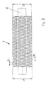
- the brush attachment 13 in the axial direction with an outer diameter D 1 in a first brush width B 1 and with an inner diameter D 2 in a second brush width B 2 on the Width of the brush roller 3 arranged in a zonal pattern.
- the brush attachment 13 is thus formed in the axial direction by alternating diameters D 1 and D 2 .
- Fig. 3 on the roller core 12 of the brush attachment 13 in the axial direction with an outer diameter D 1 in a first brush width B 1 and with an inner diameter D 2 in a second brush width B 2 over the width of the brush roller 3 is arranged helically.
- the brush roller 3 is in turn rotationally driven alternately.
- the brush widths B 1 and B 2 are unequal or preferably equally dimensioned.
- the diameter D 2 in the bristles 14 is preferably in the region formed by the cleavage site 16 and the free end of the bristles 14 (diameter D 1 ) (FIG. 2).
- the brush attachment 13 always has relatively soft bristle tips 15, even at different diameters (D 1 , D 2 ), which are always split at each bristle 14.
Landscapes
- Inking, Control Or Cleaning Of Printing Machines (AREA)
- Brushes (AREA)
Abstract
Description
- auf bedruckstoffführenden Zylindermantelflächen, einschließlich Bogenführungszylindern angeordnet sind,
- auf Aufzügen angeordnet sind, die lösbar auf Zylindern, einschließlich Bogenführungszylindern, fixierbar sind, bzw.
- eine Druckform ausbilden.
- Fig. 1
- eine Reinigungsvorrichtung mit einer Bürstenwalze als Reinigungselement und Zuführleitungen für Reinigungsflüssigkeiten (Seitenansicht),
- Fig. 2
- die erfindungsgemäße Bürstenwalze im Detail,
- Fig. 3
- eine Ausbildung der Bürstenwalze mit unterschiedlichen Durchmessern in Draufsicht.
Alternativ sind zu den Sprührohren 4, 6, 8 auch einzelne Düsen anordenbar, welche mit der entsprechenden Zuführleitung 5, 7, 9 leitungsseitig gekoppelt sind. Am Gehäuse 2 ist ferner ein aus einem zylindrischen Stab bestehendes Rakel 10 angeordnet, das bevorzugt mit einem Bürstenbesatz 13 der Bürstenwalze 3 in ständigem Eingriff ist.
Bei Bedarf ist die Bürstenwalze 3 zusätzlich axial changierend antreibbar.
In bevorzugten Ausbildung ist das Oberflächenprofil aus Molybdän oder Wolframcarbid/Kobalt gebildet oder enthält zumindest diese Materialien. Der Siegelstoff auf dem Oberflächenprofil ist bevorzugt aus der Gruppe der Polyorganosiloxane.
Die dem Zylinder 3 zugeordnete Bürstenwalze 3 weist wie beschrieben als Bürstenbesatz 13 eine Vielzahl einzelner, auf dem Walzenkern 12 endseitig fixiert angeordneter Borsten 14 auf. Jede einzelne Borste 14 ist am freien Ende in mehrere Borstenspitzen 15 aufgespaltet. Die Bürstenwalze 3 ist rotativ alternierend antreibbar, so dass wechselseitig die Vertiefungen, Erhebungen sowie die Flanken des jeweiligen Oberflächenprofils mit Siegelstoff effektiv reinigbar sind.
Breite der Bürstenwalze 3 zonenförmig angeordnet. Der Bürstenbesatz 13 ist somit in Achsrichtung durch abwechselnde Durchmesser D1 bzw. D2 gebildet.
Die Bürstenbreiten B1 bzw. B2 sind ungleich oder bevorzugt gleich dimensionierbar.
Der Durchmesser D2 liegt bei den Borsten 14 bevorzugt im Bereich der durch die Spaltstelle 16 und das freie Ende der Borsten 14 (Durchmesser D1) gebildet ist (Fig. 2). Dadurch weist der Bürstenbesatz 13 auch bei unterschiedlichen Durchmessern (D1, D2) stets an jeder Borste 14 aufgespaltete, relativ weiche Borstenspitzen 15 auf.
- 1-
- Zylinder
- 2-
- Gehäuse
- 3-
- Bürstenwalze
- 4-
- erstes Sprührohr
- 5-
- erste Zuführleitung
- 6-
- zweites Sprührohr
- 7-
- zweite Zuführleitung
- 8-
- drittes Sprührohr
- 9-
- dritte Zuführleitung
- 10
- - Rakel
- 11
- - Ablauf
- 12
- - Walzenkern
- 13
- Bürstenbesatz
- 14
- Borste
- 15
- Borstenspitze
- 16
- Spaltstelle
- B1
- erste Bürstenbreite
- B2
- zweite Bürstenbreite
- D1
- äußerer Durchmesser
- D2
- innerer Durchmesser
Claims (10)
- Reinigungsvorrichtung für einen Zylinder in einer Verarbeitungsmaschine, vorzugsweise einer Druckmaschine bzw. Lackiermaschine, mit einem eine dem Zylinder zugekehrte Öffnung aufweisenden Gehäuse zur Aufnahme einer mit diesem Zylinder in Kontakt bringbaren, drehbeweglichen Bürstenwalze mit einem Walzenkern und einem daran angeordneten Bürstenbesatz, mit wenigstens einer Zuführleitung für eine Reinigungsflüssigkeit und mit einem Ablauf zur Abführung der verschmutzten Reinigungsflüssigkeit,
dadurch gekennzeichnet, dass der Zylinder (1) eine flexible Hochdruckform oder ein Gummituch, einschließlich ein ausgespartes Gummituch, trägt und dass die Bürstenwalze (3) rotativ alternierend antreibbar ist und als Bürstenbesatz (13) eine Vielzahl einzelner, auf dem Walzenkern (12) endseitig fixiert angeordneter Borsten (14) aufweist und jede einzelne Borste (14) am freien Ende in mehrere Borstenspitzen (15) aufgespaltet ist. - Reinigungsvorrichtung für einen Zylinder in einer Verarbeitungsmaschine, vorzugsweise einer Druckmaschine bzw. Lackiermaschine, mit einem eine dem Zylinder zugekehrte Öffnung aufweisenden Gehäuse zur Aufnahme einer mit diesem Zylinder in Kontakt bringbaren, drehbeweglichen Bürstenwalze mit einem Walzenkern und einem daran angeordneten Bürstenbesatz, mit wenigstens einer Zuführleitung für eine Reinigungsflüssigkeit und mit einem Ablauf zur Abführung der verschmutzten Reinigungsflüssigkeit,
dadurch gekennzeichnet, dass der Zylinder (1) ein bedruckstoffführender Zylinder (1) mit einem Oberflächenprofil oder mit einem lösbar fixierten Aufzug mit einem Oberflächenprofil ist und dass die Bürstenwalze (3) rotativ alternierend antreibbar ist und als Bürstenbesatz (13) eine Vielzahl einzelner, auf dem Walzenkern (12) endseitig fixiert angeordneter Borsten (14) aufweist und jede einzelne Borste (14) am freien Ende in mehrere Borstenspitzen (15) aufgespaltet ist. - Reinigungsvorrichtung für einen Zylinder in einer Verarbeitungsmaschine, vorzugsweise einer Druckmaschine bzw. Lackiermaschine, mit einem eine dem Zylinder zugekehrte Öffnung aufweisenden Gehäuse zur Aufnahme einer mit diesem Zylinder in Kontakt bringbaren, drehbeweglichen Bürstenwalze mit einem Walzenkern und einem daran angeordneten Bürstenbesatz, mit wenigstens einer Zuführleitung für eine Reinigungsflüssigkeit und mit einem Ablauf zur Abführung der verschmutzten Reinigungsflüssigkeit,
dadurch gekennzeichnet, dass der Zylinder (1) ein Bogenführungszylinder mit einem Oberflächenprofil oder ein Bogenführungszylinder mit einem lösbar fixierten Aufzug mit einem Oberflächenprofil ist und auf dem Oberflächenprofil eine haftfeste Beschichtung aus einem verschleißgefährdeten Siegelstoff angeordnet ist und dass die Bürstenwalze (3) rotativ alternierend antreibbar ist und als Bürstenbesatz (13) eine Vielzahl einzelner, auf dem Walzenkern (12) endseitig fixiert angeordneter Borsten (14) aufweist und jede einzelne Borste (14) am freien Ende in mehrere Borstenspitzen (15) aufgespaltet ist. - Reinigungsvorrichtung nach Anspruch 1 oder 2 oder 3,
dadurch gekennzeichnet, dass der Bürstenbesatz (13) konzentrisch auf dem Walzenkern (12) angeordnet ist und einen gleichen äußeren Durchmesser (D1) aufweist. - Reinigungsvorrichtung nach Anspruch 1 oder 2 oder 3,
dadurch gekennzeichnet, dass jede Borste (14) ab einer Spaltstelle (16) zumindest zwei Borstenspitzen (15) von reduzierter Borstenspitzenstärke aufweist. - Reinigungsvorrichtung nach Anspruch 1 oder 2 oder 3,
dadurch gekennzeichnet, dass die Spleißtiefe der Borstenspitzen (15) etwa 3 bis 8 mm beträgt. - Reinigungsvorrichtung nach Anspruch 1 oder 2 oder 3,
dadurch gekennzeichnet, dass jede Borste (14) eine Borstenspitzenstärke von etwa 0,10 bis 0,30 mm aufweist. - Reinigungsvorrichtung nach Anspruch 1 oder 2 oder 3,
dadurch gekennzeichnet, dass die Länge der Borsten (14), einschließlich der Borstenspitzen (15), etwa 10 bis 35 mm beträgt. - Reinigungsvorrichtung nach Anspruch 1 oder 2 oder 3,
dadurch gekennzeichnet, dass auf dem Walzenkern (12) der Bürstenbesatz (13) in Achsrichtung mit einem äußeren Durchmesser (D1) in einer ersten Bürstenbreite (B1) und mit einem inneren Durchmesser (D2) in einer zweiten Bürstenbreite (B2) über die Breite der Bürstenwalze (3) zonenförmig angeordnet ist. - Reinigungsvorrichtung nach Anspruch 1 oder 2 oder 3,
dadurch gekennzeichnet, dass auf dem Walzenkern (12) der Bürstenbesatz (13) in Achsrichtung mit einem äußeren Durchmesser (D1) in einer ersten Bürstenbreite (B1) und mit einem inneren Durchmesser (D2) in einer zweiten Bürstenbreite (B2) über die Breite der Bürstenwalze (3) schraubenförmig angeordnet ist.
Applications Claiming Priority (2)
| Application Number | Priority Date | Filing Date | Title |
|---|---|---|---|
| DE200410012655 DE102004012655B4 (de) | 2004-03-16 | 2004-03-16 | Reinigungsvorrichtung für einen Zylinder in einer Verarbeitungsmaschine |
| DE102004012655 | 2004-03-16 |
Publications (1)
| Publication Number | Publication Date |
|---|---|
| EP1577094A1 true EP1577094A1 (de) | 2005-09-21 |
Family
ID=34833126
Family Applications (1)
| Application Number | Title | Priority Date | Filing Date |
|---|---|---|---|
| EP05004776A Withdrawn EP1577094A1 (de) | 2004-03-16 | 2005-03-04 | Reinigungsvorrichtung für einen Zylinder in einer Verarbeitungsmaschine |
Country Status (2)
| Country | Link |
|---|---|
| EP (1) | EP1577094A1 (de) |
| DE (1) | DE102004012655B4 (de) |
Cited By (3)
| Publication number | Priority date | Publication date | Assignee | Title |
|---|---|---|---|---|
| EP2243632A3 (de) * | 2009-04-22 | 2011-10-19 | KULLEN GmbH & Co. KG | Rotationsbürste mit unterschiedlichem Borstenbesatz |
| EP2995455A1 (de) * | 2014-09-12 | 2016-03-16 | manroland web systems GmbH | Reinigungsvorrichtung mit reinigungsbürste für eine druckmaschine |
| CN109226013A (zh) * | 2018-10-06 | 2019-01-18 | 泰州市正阳麦芽有限公司 | 一种麦芽原料加工用精选装置 |
Families Citing this family (3)
| Publication number | Priority date | Publication date | Assignee | Title |
|---|---|---|---|---|
| DE102007023625B4 (de) | 2007-05-22 | 2015-10-29 | Koenig & Bauer Ag | Vorrichtung zur Reinigung eines Zylinders in einer Druckmaschine |
| DE102007023626B4 (de) | 2007-05-22 | 2017-04-27 | Koenig & Bauer Ag | Waschvorrichtung für einen sich drehenden Zylinder in einer Druckmaschine |
| DE102010062256A1 (de) | 2010-12-01 | 2012-06-06 | Manroland Ag | Reinigungsvorrichtung für einen Zylinder einer Verarbeitungsmaschine |
Citations (2)
| Publication number | Priority date | Publication date | Assignee | Title |
|---|---|---|---|---|
| US5974975A (en) * | 1997-12-10 | 1999-11-02 | Heidelberger Druckmaschinen | Cleaning device for cylinders of printing presses |
| DE20008043U1 (de) | 2000-05-04 | 2000-07-13 | MAN Roland Druckmaschinen AG, 63075 Offenbach | Reinigungsvorrichtung für einen Zylinder einer Druckmaschine |
Family Cites Families (1)
| Publication number | Priority date | Publication date | Assignee | Title |
|---|---|---|---|---|
| DE20307718U1 (de) * | 2003-05-17 | 2003-11-06 | MAN Roland Druckmaschinen AG, 63075 Offenbach | Reinigungsvorrichtung für einen Zylinder einer Verarbeitungsmaschine |
-
2004
- 2004-03-16 DE DE200410012655 patent/DE102004012655B4/de not_active Expired - Fee Related
-
2005
- 2005-03-04 EP EP05004776A patent/EP1577094A1/de not_active Withdrawn
Patent Citations (2)
| Publication number | Priority date | Publication date | Assignee | Title |
|---|---|---|---|---|
| US5974975A (en) * | 1997-12-10 | 1999-11-02 | Heidelberger Druckmaschinen | Cleaning device for cylinders of printing presses |
| DE20008043U1 (de) | 2000-05-04 | 2000-07-13 | MAN Roland Druckmaschinen AG, 63075 Offenbach | Reinigungsvorrichtung für einen Zylinder einer Druckmaschine |
Cited By (3)
| Publication number | Priority date | Publication date | Assignee | Title |
|---|---|---|---|---|
| EP2243632A3 (de) * | 2009-04-22 | 2011-10-19 | KULLEN GmbH & Co. KG | Rotationsbürste mit unterschiedlichem Borstenbesatz |
| EP2995455A1 (de) * | 2014-09-12 | 2016-03-16 | manroland web systems GmbH | Reinigungsvorrichtung mit reinigungsbürste für eine druckmaschine |
| CN109226013A (zh) * | 2018-10-06 | 2019-01-18 | 泰州市正阳麦芽有限公司 | 一种麦芽原料加工用精选装置 |
Also Published As
| Publication number | Publication date |
|---|---|
| DE102004012655A1 (de) | 2005-10-06 |
| DE102004012655B4 (de) | 2014-02-27 |
Similar Documents
| Publication | Publication Date | Title |
|---|---|---|
| EP0081697B1 (de) | Verfahren und Vorrichtung zum Aufbringen von härteren Teilchen auf ein kreisrundes oder längskantenloses drahtförmiges Gebilde | |
| EP0199084A1 (de) | Verfahren zur Oberflächenbehandlung eines Druckmaschinenzylinders, Druckmaschinenzylinder sowie Verwendung derselben | |
| DE69911910T2 (de) | Vorrichtung zum Aufbringen von Schichten aus Glasur und dergleichen auf keramischen Gegenständen | |
| EP2040931B1 (de) | Stochastisch gelaserte filmwalze | |
| DE102004012655B4 (de) | Reinigungsvorrichtung für einen Zylinder in einer Verarbeitungsmaschine | |
| DE10225541A1 (de) | Verfahren und Vorrichtung zum Herstellen eines hülsenförmigen Gummituchs | |
| EP0985530A3 (de) | Farbwerk in einer Rotations-Offsetdruckmaschine mit einer Farbauftragswalze zur Verringerung des Pereffektes der Druckfarbe | |
| EP0279295B1 (de) | Farbwerk | |
| EP0473947B1 (de) | Klischeeaufnahme und Folienklischee | |
| WO2016177721A1 (de) | Reinigungsvorrichtung für eine walze, druck- oder beschichtungswerk sowie verfahren zum reinigen einer walze | |
| EP2570194B1 (de) | Rakel-Dosiersystem | |
| DE102004005576A1 (de) | Verfahren zum Betrieb einer Lackier- oder Druckmaschine | |
| DE10346659B3 (de) | Reinigungseinrichtung für eine zylindrische Fläche in einer Druckmaschine | |
| CH652347A5 (de) | Vorrichtung zum aufbringen eines fluessigen bzw. halbfluessigen mediums auf die druckplatte einer druckmaschine, insbesondere offsetdruckmaschine. | |
| EP1466729B1 (de) | Walze für eine Druckmaschine und Verfahren zur Herstellung einer Walze | |
| EP1577093A1 (de) | Reinigungsvorrichtung für ein rotationssymmetrisches Bauteil in einer Verarbeitungsmaschine | |
| DE20307718U1 (de) | Reinigungsvorrichtung für einen Zylinder einer Verarbeitungsmaschine | |
| EP0454280B1 (de) | Rasterwalze für ein Auftragswerk mit einer Näpfchengravur | |
| EP0845354B1 (de) | Farbkasten für Rotationsdruckmaschinen | |
| DE102006049150B4 (de) | Farbwerk einer Rotationsdruckmaschine mit einem aus mindestens vier aneinandergereihten Walzen bestehenden Walzenzug | |
| DE102005003337A1 (de) | Reinigungseinrichtung für eine zylindrische Fläche in einer Druckmaschine | |
| DE19718549B4 (de) | Druckmaschine | |
| DE102010062256A1 (de) | Reinigungsvorrichtung für einen Zylinder einer Verarbeitungsmaschine | |
| DE2055897A1 (de) | Druckerpresse und Druckverfahren | |
| DE1561045A1 (de) | Feuchtwerk fuer Offset-Rotationsdruckmaschinen |
Legal Events
| Date | Code | Title | Description |
|---|---|---|---|
| PUAI | Public reference made under article 153(3) epc to a published international application that has entered the european phase |
Free format text: ORIGINAL CODE: 0009012 |
|
| 17P | Request for examination filed |
Effective date: 20050624 |
|
| AK | Designated contracting states |
Kind code of ref document: A1 Designated state(s): AT BE BG CH CY CZ DE DK EE ES FI FR GB GR HU IE IS IT LI LT LU MC NL PL PT RO SE SI SK TR |
|
| AX | Request for extension of the european patent |
Extension state: AL BA HR LV MK YU |
|
| AKX | Designation fees paid |
Designated state(s): AT BE BG CH CY CZ DE DK EE ES FI FR GB GR HU IE IS IT LI LT LU MC NL PL PT RO SE SI SK TR |
|
| RAP1 | Party data changed (applicant data changed or rights of an application transferred) |
Owner name: MANROLAND AG |
|
| 17Q | First examination report despatched |
Effective date: 20120126 |
|
| 19U | Interruption of proceedings before grant |
Effective date: 20120201 |
|
| 19W | Proceedings resumed before grant after interruption of proceedings |
Effective date: 20140203 |
|
| STAA | Information on the status of an ep patent application or granted ep patent |
Free format text: STATUS: THE APPLICATION HAS BEEN WITHDRAWN |
|
| 18W | Application withdrawn |
Effective date: 20140311 |