EP1577018A2 - Beschichtungsvorrichtung und -verfahren - Google Patents
Beschichtungsvorrichtung und -verfahren Download PDFInfo
- Publication number
- EP1577018A2 EP1577018A2 EP05251588A EP05251588A EP1577018A2 EP 1577018 A2 EP1577018 A2 EP 1577018A2 EP 05251588 A EP05251588 A EP 05251588A EP 05251588 A EP05251588 A EP 05251588A EP 1577018 A2 EP1577018 A2 EP 1577018A2
- Authority
- EP
- European Patent Office
- Prior art keywords
- coating
- substrate
- spray
- coating solution
- casing
- Prior art date
- Legal status (The legal status is an assumption and is not a legal conclusion. Google has not performed a legal analysis and makes no representation as to the accuracy of the status listed.)
- Withdrawn
Links
Images


Classifications
-
- B—PERFORMING OPERATIONS; TRANSPORTING
- B05—SPRAYING OR ATOMISING IN GENERAL; APPLYING FLUENT MATERIALS TO SURFACES, IN GENERAL
- B05B—SPRAYING APPARATUS; ATOMISING APPARATUS; NOZZLES
- B05B13/00—Machines or plants for applying liquids or other fluent materials to surfaces of objects or other work by spraying, not covered by groups B05B1/00 - B05B11/00
-
- B—PERFORMING OPERATIONS; TRANSPORTING
- B05—SPRAYING OR ATOMISING IN GENERAL; APPLYING FLUENT MATERIALS TO SURFACES, IN GENERAL
- B05B—SPRAYING APPARATUS; ATOMISING APPARATUS; NOZZLES
- B05B7/00—Spraying apparatus for discharge of liquids or other fluent materials from two or more sources, e.g. of liquid and air, of powder and gas
- B05B7/02—Spray pistols; Apparatus for discharge
- B05B7/025—Nozzles having elongated outlets, e.g. slots, for the material to be sprayed
-
- B—PERFORMING OPERATIONS; TRANSPORTING
- B05—SPRAYING OR ATOMISING IN GENERAL; APPLYING FLUENT MATERIALS TO SURFACES, IN GENERAL
- B05B—SPRAYING APPARATUS; ATOMISING APPARATUS; NOZZLES
- B05B7/00—Spraying apparatus for discharge of liquids or other fluent materials from two or more sources, e.g. of liquid and air, of powder and gas
- B05B7/02—Spray pistols; Apparatus for discharge
- B05B7/08—Spray pistols; Apparatus for discharge with separate outlet orifices, e.g. to form parallel jets, i.e. the axis of the jets being parallel, to form intersecting jets, i.e. the axis of the jets converging but not necessarily intersecting at a point
- B05B7/0807—Spray pistols; Apparatus for discharge with separate outlet orifices, e.g. to form parallel jets, i.e. the axis of the jets being parallel, to form intersecting jets, i.e. the axis of the jets converging but not necessarily intersecting at a point to form intersecting jets
- B05B7/0815—Spray pistols; Apparatus for discharge with separate outlet orifices, e.g. to form parallel jets, i.e. the axis of the jets being parallel, to form intersecting jets, i.e. the axis of the jets converging but not necessarily intersecting at a point to form intersecting jets with at least one gas jet intersecting a jet constituted by a liquid or a mixture containing a liquid for controlling the shape of the latter
-
- B—PERFORMING OPERATIONS; TRANSPORTING
- B05—SPRAYING OR ATOMISING IN GENERAL; APPLYING FLUENT MATERIALS TO SURFACES, IN GENERAL
- B05B—SPRAYING APPARATUS; ATOMISING APPARATUS; NOZZLES
- B05B7/00—Spraying apparatus for discharge of liquids or other fluent materials from two or more sources, e.g. of liquid and air, of powder and gas
- B05B7/02—Spray pistols; Apparatus for discharge
- B05B7/08—Spray pistols; Apparatus for discharge with separate outlet orifices, e.g. to form parallel jets, i.e. the axis of the jets being parallel, to form intersecting jets, i.e. the axis of the jets converging but not necessarily intersecting at a point
- B05B7/0884—Spray pistols; Apparatus for discharge with separate outlet orifices, e.g. to form parallel jets, i.e. the axis of the jets being parallel, to form intersecting jets, i.e. the axis of the jets converging but not necessarily intersecting at a point the outlet orifices for jets constituted by a liquid or a mixture containing a liquid being aligned
Definitions
- the present invention relates to a coating apparatus to produce ink jet recording media by spraying a coating solution to form liquid droplets to coat a substrate, and to a coating method in which a coating apparatus is employed.
- Non-Patent Document 1 various methods in which a coating solution is accurately applied onto a long belt-shaped substrate are proposed, for example, a known dip coating method, a blade coating method, an air knife coating method, a wire bar coating method, a gravure coating method, a reverse coating method, a reverse roll coating method, an extrusion coating method, a slide bead coating method, as well as a curtain coating method. Further, in these coating methods, in order to achieve a uniform dried layer thickness across the width of the substrate with high accuracy, coating is carried out while paying particular attention to accuracy and uniformity of coating thickness during the entire coating process (prior to as well as after coating).
- the coating apparatus which includes a flow rate regulating type dice, is capable of achieving high speed, thin layers and multilayer simultaneous coating. Due to these features, it is widely employed as a coating apparatus for light-sensitive photographic materials, ink jet recording materials, and magnetic recording materials.
- aforesaid coating apparatus is a slide bead coating apparatus, proposed by Russell et al in Patent Document 1.
- an extrusion coating apparatus is also widely employed.
- a curtain coating apparatus which is a flow rate regulating type apparatus including dice, is also widely employed.
- a maintained coating solution called a bead
- a curtain-shaped coating solution layer is subjected to free-fall and coating is carried out while positioning a substrate under the falling solution.
- the coating apparatus and the substrate are in contact continuous employing the coating solution such as a bead and curtain film, due to its principle.
- the flow rate of the coating solution from the coating apparatus should always be constant and be continuously fed. Namely, in order to continuously form the coating layer, as well as to maintain a constant coating layer thickness with high accuracy, a coating solution amount more than the specified is required. Accordingly, in these systems, when the amount of coating solution discharged from the coating apparatus is excessively reduced, it becomes difficult to achieve the purpose for obtaining uniform layer thickness.
- the desired layer is excessively thin (for example, about 1 to about 50 ⁇ m)
- it becomes necessary to increase the layer thickness by means of increasing the total amount of the coating solution by increasing the amount of solvents in the aforesaid coating solution.
- the viscosity of the coating solution is low, the coating layer flows on the substrate. As a result, it is difficult to form a stably uniform coating layer.
- Patent Documents 4 and 5 A coating apparatus employing a spray is disclosed in Patent Documents 4 and 5, and it is applicable to highly viscous coating solution like adhesives, which however is not adequate to be used as an apparatus for a thin layer of an overcoating layer which the present invention targets.
- an apparatus described in said Patent Documents 2 and 3 scattering of liquid droplets and resulting spot type defects on the coated surface as well as stains on the apparatus tend to occur.
- Patent Document 3 a study was carried out for a preventive method of liquid droplet scattering to describe structures of droplet scattering prevention equipment, however it was not sufficiently effective and not completed because the condition ranges of the equipment are not described.
- the objective of the present invention is to solve these problems caused by the conventional technique and to provide a coating apparatus and a coating method which prevents scattering of surplus droplets, spot type non-uniformity created by scattered droplets and staining of the apparatus (including coating defects from drops of dried layer of staining materials).
- the objective can be achieved by the following apparatus and method.
- the relationship between the reduced pressure of the first casing containing the spray coating device for coating on the substrate, and the reduced pressure of the second casing located opposite of the substrate relative to the first casing was studied to establish optimal coating condition so that conveyance of a substrate and a coating on a substrate does not cause spot type defects and provide a uniform satisfactory coating situation.
- the coating apparatus and the coating method of this invention which uses a spray coating device discharging auxiliary gas toward the substrate to be coated by employing guide plates and current plates, it became possible to provide a coating apparatus and a coating method which can produce ink jet recording media such as recording sheets which has stable quality without spot type defects or staining to the apparatus caused by scattering of large liquid droplets.
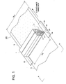
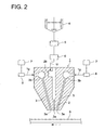
- Figs. 1 and 2 are perspective views of spray coating device 1 integral in a manufacturing apparatus for ink jet recording media and a schematic sectional view of spray coating device 1.
- reference numeral 1 is the spray coating device
- S is a long belt-shaped substrate.
- Substrate S is conveyed in the direction indicated by an arrow in Fig. 1 at a constant rate, employing a conveyance means (not shown).
- Coating solution nozzle 2 and gas nozzle 3 of spray coating device 1 span the full width of substrate S which is perpendicular to the conveyance direction and are arranged so as to face the surface to be coated of substrate S.
- the coating solution which is discharged from coating solution discharge section 2a of coating solution nozzle 2 is sprayed in the form of liquid droplets by the pressurized gas discharged from gas discharge section 3a of gas nozzle 3, and coating is carried out so that the droplets are deposited on conveyed substrate S.
- Spray coating device 1 includes a pair of gas nozzles 3, having gas pocket 3b, and coating solution nozzle 2, having coating solution pocket 2b.
- a coating solution is composed of, for example, a functional compound containing solution, having a viscosity (preferably from 0.1 to 250 mPa ⁇ s), capable of forming liquid droplets without forming threads.
- This coating solution is fed into preparation tank 4, and is subsequently supplied to coating solution pocket 2b via pump 5 and flow meter 6, and is then led to coating solution nozzle 2. Further, pressurized air which is fed to pocket 3b via control valve 8 from pressurized air source 7 is supplied to gas nozzles 3.
- the coating solution is supplied from preparation tank 4 so that the specified coating amount is discharged from coating solution nozzle 2.
- pressurized air is ejected from a pair of gas nozzles 3, whereby the coating solution is shaped into liquid droplets which are sprayed onto substrate S to be deposited.
- Fig. 3 is an enlarged cross-section of the nozzle end of spray coating device 1, showing as well the pattern of liquid droplets formed on substrate S and the ejected state of liquid droplets.
- the coating solution which is discharged from coating solution nozzle 2, is finely divided to form liquid particles, employing compressed air supplied from gas nozzles 3 which are structured adjacent to both sides of coating solution nozzle 2, whereby substantially spherical liquid droplets 9 are formed, which subsequently are deposited uniformly on the surface of substrate S.
- Fig. 3 shows a model in which substrate S is composed of support Sa having thereon ink absorptive layer Sb, as a composition layer. It is preferable that the spray pattern area of liquid droplets of the coating solution, which is deposited on substrate S, remains uniform. It is also particularly preferable that the length in the conveyance direction (described as length of spray in Fig. 3) remains uniform across the coating width. Further, it is preferable that spreading angle ⁇ of the group of liquid droplets which are sprayed toward the substrate from the opening of coating solution nozzle 2 is uniform across the coating width.
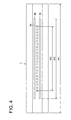
- Fig. 4 is a bottom view of the spray coating device 1 in Fig. 3 viewed from the coating solution discharge section 2a and shows plural end openings of coating solution discharge section 2a aligned across the coating width, and gas discharge section 3a.
- coating solution discharge section 2a shown in Fig. 4 twenty-three coating solution discharge sections 2a, having a rectangular opening, are aligned across the coating width.
- the shape of the discharge section for coating solution is not limited to being rectangular and may also be circular.
- the discharge section may also be a slit extending across the coating width.
- 50 to 300 ⁇ m is functional and it is preferable that the pitch (interval) is 100 to 3,000 ⁇ m.
- gas discharge sections 3a which extend across the coating width are structured adjacent on both sides of coating solution discharge sections 2a.
- the gas discharge section is not limited to a slit and may be a plurality of circular or rectangular end openings similar to the coating solution discharge sections.
- Coating solution discharge sections 2a are arranged at equal intervals.
- gas discharge sections 3a are also arranged at equal intervals when they are circular or rectangular.
- coating solution discharge sections 2a and gas discharge sections 3a may alternatively be structured in a zigzag pattern when the openings of gas discharge section 3a are circular or rectangular.
- Fig. 5 is a perspective exploded view of spray coating device 1.
- reference codes 1b and 1d are die blocks which form a coating slit of the specified length, and allow the coating solution to flow down the aforesaid slit.
- Die block 1b receives the coating solution supplied from a coating solution supply source (not shown) and includes a coating solution supply opening 1f which allows the coating solution to pass into coating solution pocket 2b.
- the coating solution which is retained in coating solution pocket 2b, flows down the coating solution slit formed between die blocks 1b and 1d.
- Symbol 1c is a shim (packing metal) interposed between block 1b and 1d which divides the slit for the coating solution formed between die blocks 1b and 1d in the perpendicular direction so as to form a plurality of coating solution nozzles across the coating width.
- the slit for the coating solution may be changed into either circular or rectangular openings.
- the shim (packing metal) represented on 1c is not employed.
- 1a and 1e each is a gas block and forms a gas nozzle via the gap with die blocks 1b and 1d respectively, through which compressed gas passes.
- the gas nozzle is a slit which extends across the coating width.
- Compressed air is supplied from an air source (not shown) to air supply channel 1g of each gas block, and after a temporary stay in gas pocket 3b, flows downward through the gas nozzles formed in the gap between die blocks 1b and 1d and gas blocks 1a and 1e respectively.
- the coating solution which flows down the channel forming the coating solution nozzle, and compressed air which flows down the two separate gas nozzles, collide just below the coating solution discharge section 2a, which is the bottom section of spray coating device 1, whereby liquid droplets are formed and are deposited onto the substrate S which is to be coated.
- the angle of gas nozzles 3 with respect to coating solution nozzle 2 is preferably in the range of 5 to 50 degrees. Further, it is possible to appropriately select the distance between coating solution discharge section 2a of spray coating device 1 and substrate S to be in the range of about 2 to about 50 mm.
- the supply rate of the coating solution from the coating solution nozzle varies, since it depends on the desired coating layer thickness, the concentration of coating solution, the coating speed, and the like.
- the coating amount on the substrate is preferably in the range of about 1 to about 50 g/m 2 .
- the coating amount is less than 1 g/m 2 , it is difficult to form a uniformly stable coating layer, while when it exceeds 50 g/m 2 , it becomes difficult to exhibit the desired effects of the present invention due to adverse effects as to a drying load.
- the wet layer thickness of the coating solution is from 1 to 50 ⁇ m, and is preferably from 5 to 30 ⁇ m.
- gases to be ejected from gas nozzles 3 are not particularly limited as long as they are suitable for coating, and commonly air is employed.
- Gas supply conditions are preferably in the range of about 1 to about 50 CMM/m (flow rate per coating width).
- inner pressure in the gas nozzles 3 is preferably at least 10 kPa.
- the viscosity of coating solutions is preferably from 0.1 to 250 mPa ⁇ s, is preferably from 0.1 to 50 mPa ⁇ s, and is more preferably from 0.1 to 20 mPa ⁇ s.
- the surface tension of coating solutions is adjusted from 20 to 70 mN/m, preferably from 20 to 50 mN/m, and more preferably from 20 to 30 mN/m.
- liquid droplets are formed by allowing a gas flow to collide with the coating solution while employing spray coating devices 1, a uniform spray is easily achieved by employing gas having an inner gas pressure of at least 10 kPa, more preferably at least 20 kPa, and still more preferably at least 50 kPa.
- a coating solution is scattered in the form of discontinuous liquid droplets across the coating width, instead of forming threads, whereby it is possible to uniformly apply the coating solution onto substrate S, even though the amount of the coating solution is small. As a result, it is possible to make a uniform coating thickness. Further, despite the supply of discontinuous liquid droplets onto substrate S, the amount of coating solution can be decreased to result in a minimal drying load.
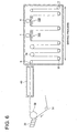
- Fig. 6 is a schematic diagram showing one example of a coating production line provided with spray coating device 1 downstream of an ordinary slide bead type coating device 30 of the flow rate regulating type explained above.
- substrate S is employed composed of a support coated with a composition layer.
- a plurality of spray coating devices 1 are arranged along the drying process.
- forming the composition layer, as well as coating the overcoating layer (being the uppermost layer) according to the present invention in a single production line, as stated above, is called "on-line coating".
- a support from a master roll is allowed to pass over conveyance roller 31, employing a conveyance means (not shown). Subsequently, during the process in which the support is reversed via the position of back-up roller 32, a coating solution forming a porous ink absorptive layer (a composition layer), which is supplied from a flow rate regulating type slide bead coating apparatus 30, is coated to form substrate S. Since the coating solution of the porous ink absorptive layer is composed of hydrophilic binders, the coated support is temporarily cooled and set in cooling zone. 40.
- Substrate S composed of the resulting support having thereon an ink absorptive layer is conveyed to a drying zone.
- the drying zone there are alternately arranged reversers 33 which achieves reversing conveyance via blown air with no contact with the newly coated layer surface, and an ordinary conveyance roller 34 which performs reverse conveyance in contact with the back surface of substrate S, whereby substrate S is conveyed.
- drying is carried out via blown warm air (the warm air blowing means is not shown).
- another coating layer is deposited via liquid droplet spraying, as described above, employing two spray coating devices 1.
- At least one of two spray coating devices is arranged at or after the drying end point.
- two spray coating devices are employed, however, the number of apparatus may be only 1 or 3 or more.
- the coating speed may not be necessarily specified, since it varies depending on the types of coating solutions, the concentration, the solvent content, and the drying capacity.
- the coating speed is preferably from 50 to 300 m/min, but preferred is a coating speed of 100 to 300 m/min.
- the subsequent coating is preferably carried out at or after the decreasing drying of the composition layer formed on the support, and is more preferably carried out at or after end point of the drying process.
- a coating process in which the aforesaid composition layer is coated, employing slide bead coating, and a coating process in which coating is carried out employing spray coating device 1 of the present invention are continuously performed employing a single production line (called on-line coating).
- drying is carried out by blowing drying air, conditioned to a specified temperature and humidity, onto the coated surface or the back of the support to prevent cracking of the layer, while continuously conveying a wet coated layer.
- substrate S refers to an object to be coated while employing the coating method of the present invention in which coating is carried out by spraying liquid droplets of a coating solution, and its structure is not particularly limited.
- the aforesaid long belt shaped substrates S, as well as those including the aforesaid substrate S having thereon a composition layer are preferred because it is possible to efficiently achieve the desired effects of the present invention.
- aforesaid substrates S are not limited to those above.
- substrate S is conveyed relative to coating solution discharge section 2a of spray coating device 1, whereby continuous coating production is performed.
- the coating solution discharge section 2a has a width which is equal to or greater than the coating width of substrate S (which refers to the length of the coating portion of substrate S perpendicular to the conveyance direction of the aforesaid substrate S), and is arranged so that substrate S passes under the falling coating solution which is then applied onto substrate S only by conveying substrate S relative to the coating apparatus.
- the aforesaid belt-shaped substrate S itself is allowed to be conveyed in the longitudinal direction thereof and the coating solution discharge section 2a is positioned across the width (the direction perpendicular to the longitudinal direction) of aforesaid substrate S.
- the coating solution discharge section 2a is positioned across the width (the direction perpendicular to the longitudinal direction) of aforesaid substrate S.
- liquid droplets which are sprayed from the coating solution discharge section 2a of the spray coating device 1, are required to satisfy the following conditions:
- the uniform droplet diameter across the coating width specifically refers to variation of the average liquid droplet diameter of less than or equal to ⁇ 20 percent and preferably is less than or equal to ⁇ 10 percent.
- a coating solution is sprayed employing spray coating device 1 which sprays the aforesaid coating solution in the form of liquid droplets, and the state of the spray is allowed to stabilize.
- spray coating device 1 which sprays the aforesaid coating solution in the form of liquid droplets, and the state of the spray is allowed to stabilize.
- the spray state is not stabilized due to variation of the discharge volume of the coating solution as well as variation of gas pressure.
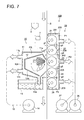
- Fig. 7 is a cross-sectional view showing coating apparatus 100 coating a substrate to produce ink jet recording paper sheets.
- Coating apparatus 100 is composed of coating means 10 including spray coating device 1 and conveying means 20 to convey substrate S.
- Coating means 10 is composed of first casing 10A including spray coating device 1 and its outer casing 11 and inner casing 12, and of waste liquid collecting means 13 and pressure reducing means 14.
- Aperture area 11a located on the right side of outer casing 11 in Fig. 7 forms gap g1 facing a conveying passage of substrate S.
- Aperture areas 11b and 11c located on the left side of outer casing 11, are connected to pressure reducing means 14 via air suction ducts 15.
- the interior pressure of outer casing 11 is maintained at a decompression Ps value of -50 through -3,000 Pa.
- the preferable range is -100 to -2,000Pa, and more preferably - 100 to -1,000Pa.
- Spray coating device 1 is located in inner casing 12 supported in outer casing 11.
- Inner casing 12 has a shielding wall on which a mist of the coating solution is scattered, which is ejected from coating nozzle 2 of spray coating device 1.
- This coating solution spattered on the shielding wall slides down on slope 12a and passes through liquid waste pipe 13a to be collected by liquid waste collecting means 13.
- Conveying means 20 is located behind substrate S which faces aperture area 11a of coating means 10.
- Conveying means 20 is composed of the second casing 200 forming plural decompression chambers 201, 202 and 203 separated from each other, and plural rollers including first feed rollers 21 and 22 located rotatably in decompression chamber (first decompression chamber) 201 at the entrance for substrate S, second feed rollers 24 and 25 located rotatably in decompression chamber (third decompression chamber) 203 at the exit of substrate S and back-up roller 23 located rotatably in decompression chamber (second decompression chamber) 202 facing coating solution nozzle 2 of spray coating device 1.
- Respective reduced pressure values P1 and P3 of decompression chambers 201 and 203, which are connected to pressure reducing means 26, are maintained at -50 to -3,000 Pa, when substrate S is conveyed.
- Reduced pressure value P2 of decompression chamber 202, which is connected to pressure reducing means 27, is maintained at -50 to -3,000 Pa, when substrate S is conveyed.
- the preferable range of pressure values P1, P2 and P3 are -100 to -2,000 Pa, and more preferably, are -100 to -1,000 Pa.
- P1, P2 and P3 are set in this range and it is preferable to maintain the relationship of P1, P2, P3 and Ps, as P1 ⁇ Ps ⁇ P2, and P3 ⁇ Ps ⁇ P2, and it is preferable that, 0 ⁇ P2-Ps ⁇ 1,000 Pa, 0 ⁇ Ps-P1 ⁇ 1,000 Pa, 0 ⁇ Ps-P3 ⁇ 1,000 Pa, and more preferable that, 0 ⁇ P2-Ps ⁇ 500 Pa, 0 ⁇ Ps-P1 ⁇ 500 Pa, 0 ⁇ Ps-P3 ⁇ 500 Pa.
- gap g1 between substrate S being in contact with circumferential surface of first feed roller 22 and the tip of aperture area 11a of outer casing 11 is maintained at 1 to 10 mm and more preferably 1 to 5 mm.
- Gap g2 between the circumferential surface of first feed rollers 21 and 22, and gap g3 between circumference surface of second feed rollers 24 and 25 are maintained at 0.1 to 2 mm.
- Gap g4 between partition 204 separating decompression chambers 201 and 202, and circumferential surface of first feed roller 22, and gap g5 between partition 205 separating decompression chambers 202 and 203, and circumferential surface of second feed roller 25 are also maintained at 0.1 to 2 mm.
- substrate S In decompression chamber 201 at the entrance of sheet conveyance, because substrate S is conveyed by rotating second rollers 21 and 22 while being aspirated by the reduced pressure, substrate S can be conveyed to the spray coating section in a flat and stable condition.
- substrate S is conveyed by rotating backup roller 23 and is maintained to be stable and flat by means of pressure reduction in outer casing 11 and in decompression chamber 202.
- substrate S after spray coating can be conveyed in a stable and flat condition.
- Fig. 8 is a frontal view of conveying means 20.
- Masking plates 50 are located on both sides in the width direction of substrate S (hatched parts in Fig. 8). Masking plates 50 are located in the vicinity of coating solution discharge section 2a of spray coating device 1, and shield outer edges to form non-forming portions of coating solution layer (refer to Figs. 1 and 8). It is preferred that masking plates can change gap g6 and the angle relative to substrate S. Gap g6 is preferably 1 to 15 mm, and more preferably 1 to 10 mm, and still more preferably 1 to 5 mm. Though the masking plates can be made of various materials, water repellant Teflon (R) material or Teflon (R) coating material is preferred. Auxiliary aspirating nozzles 70 are installed near masking plates 50 to aspirate surplus droplets. The dotted line shown in Fig. 8 represents the locating position of spray coating device 1 facing backup roller 23 of conveying means 20.
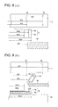
- Fig. 9(a) is a schematic plan view explaining the dimensions of the respective width of spray coating device 1, substrate S and masking plates 50.
- Fig. 9(b) is cross-section A-A of Fig. 1 and also shows the dimensions of the respective width of spray coating device 1, substrate S and masking plates 50.
- the total width of spray coating device 1 is W1
- the width of liquid coating discharge section 2a of liquid coating nozzle 2 is W2
- the width of discharge section of gas nozzle 3 is W3 (refer to Fig. 4).
- Substrate S has total width Ws1 and the total width of ink absorption layer Sb is Ws2.
- Distance W5 between masking plates 50 is arranged to be a little less than total width Ws2 of ink absorption layer Sb, and is arranged to be a little longer than width W2 of coating solution discharge section 2a (Ws2 > W5 > W2).
- Droplet particles 9 which are discharged from coating solution discharge section 2a and are sprayed by gas nozzle 3 are scattered at an angle of ⁇ , and are deposited onto substrate S to create a uniform coating layer, while preventing coating by masking plates 50 in the vicinity of both edges of substrate S, effectively forming coating width Ws3.
- the range of conditions where the conveying condition of the substrate and the coating condition of the substrate are favorable were determined, regarding the coating apparatus and the coating method of this invention, by researching the relationship between the reduced pressure value in the first casing containing the spray coating device for spray-coating the substrate and the reduced pressure value in the second casing located opposite of the substrate.
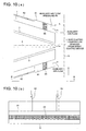
- auxiliary gas flow is conducted on both the upper side and lower side of the spray coating device, and the auxiliary gas flow is lead to the vicinity of a coating position and auxiliary gas flow guide plates 81 are installed so that droplets of spray coating are not widely diffused but are lead to the coating position uniformly and the objective to obtain coating uniformity by use of auxiliary gas flow is achieved by optimizing gap L between auxiliary gas flow guide plates 81 and the substrate.
- Ph1 is in the range of 100 Pa to 5,000 Pa, and more preferably 100 Pa to 1,000 Pa
- Ph2 is preferably in the range of 100 Pa to 50,000 Pa, and more preferably 1,000 Pa to 50,000 Pa, and still more preferably 5,000 Pa to 50,000 Pa.
- the pressure of auxiliary air flow was low, preventive effects against scattering of droplets could not be sufficiently achieved, and spot type defects caused by droplets were observed on the condition when the pressure was below 100 Pa.
- the pressure of auxiliary air flow was high, the auxiliary air flow disturbed sprayed droplets and non-uniformity was caused by the air turbulence.
- auxiliary gas flow guide plates 81 their existence affects the auxiliary gas flow, and without auxiliary gas flow guide plates 81, diffusion of auxiliary gas flow occurs and prevention of droplets from scattering becomes insufficient.
- current plates 85 are installed into auxiliary gas flow guide plates 81.
- a porous material is applied for current plates 85, such as sponge material which allows gas to permeate through the material. Compressed air is sent to supply port 82 via a small tube, and because it is diffused in auxiliary gas flow guide plates 81, current plates 85 has a large effect to equalize the air flow across the width direction perpendicular to the conveyance direction.
- current plates 85 without these, uneven pressure distribution and occurrence of droplets were observed on specific positions across the substrate width. However, after installation of current plates 85, uniform coating was obtained without droplet spotting.
- coating was conducted while changing the reduced pressure value of each section in various way.
- the coating solution, the substrate, the coating speed and the wet layer thickness which were employed were arranged as follows.
- Coating solution liquid of 1 percentage by mass in which water-soluble dye shown in Chem. 1 is dissolved in water
- Substrate Polyethylene laminated paper made in such a way that a support material is coated with an ink absorption layer and dried
- coating was conducted while changing gap between the first casing of the spray coating device and a substrate and also a gap between the masking plates and a substrate.
- the coating solution, the substrate, the coating speed and the wet layer thickness which were employed were as follows.
- the masking plates were made of Teflon (R), however they can also be of other material coated with Teflon(R).
- Coating solution liquid of 1 percentage by mass in which water-soluble dye shown in Chem. 2 is dissolved in water
- Substrate Employed was polyethylene laminated paper made in such a way that a support material is coated with an ink absorption layer and dried.
- coating was conducted in order to confirm effectiveness of the masking plate, the change of the plate materials, the change of the angle of the plates and auxiliary aspiration nozzles.
- the coating solution, the substrate, the coating speed and the wet layer thickness which were employed were arranged as follows.
- auxiliary aspiration nozzle 70 illustrated in Fig. 9(b)
- surplus liquid was aspirated and spot type defects did not occur.
- Substrate polyethylene laminated paper made of a support material coated with an ink absorption layer and then dried.
- the coating solution, the substrate, the coating speed, the wet layer thickness employed were arranged as follows.
Landscapes
- Application Of Or Painting With Fluid Materials (AREA)
- Coating Apparatus (AREA)
- Ink Jet Recording Methods And Recording Media Thereof (AREA)
Applications Claiming Priority (4)
| Application Number | Priority Date | Filing Date | Title |
|---|---|---|---|
| JP2004079902 | 2004-03-19 | ||
| JP2004079902A JP2005262703A (ja) | 2004-03-19 | 2004-03-19 | 塗布装置及び塗布方法 |
| JP2004084675A JP2005270724A (ja) | 2004-03-23 | 2004-03-23 | 塗布装置及び塗布方法 |
| JP2004084675 | 2004-03-23 |
Publications (1)
| Publication Number | Publication Date |
|---|---|
| EP1577018A2 true EP1577018A2 (de) | 2005-09-21 |
Family
ID=34840258
Family Applications (1)
| Application Number | Title | Priority Date | Filing Date |
|---|---|---|---|
| EP05251588A Withdrawn EP1577018A2 (de) | 2004-03-19 | 2005-03-16 | Beschichtungsvorrichtung und -verfahren |
Country Status (2)
| Country | Link |
|---|---|
| US (1) | US20050208225A1 (de) |
| EP (1) | EP1577018A2 (de) |
Cited By (3)
| Publication number | Priority date | Publication date | Assignee | Title |
|---|---|---|---|---|
| EP1625893A1 (de) * | 2004-08-10 | 2006-02-15 | Konica Minolta Photo Imaging, Inc. | Sprühbeschichtungsverfahren, Sprühbeschichtungsanordnung und Tintenstrahlaufzeichnungsblatt |
| WO2007144230A1 (de) * | 2006-06-12 | 2007-12-21 | Voith Patent Gmbh | Vorrichtung zur beschichtung einer laufenden papier-, karton- oder anderen faserstoffbahn |
| CN103373101A (zh) * | 2012-04-27 | 2013-10-30 | 赫尔曼-布罗克哈根两合公司 | 用于生产具有涂层的部件的方法及装置 |
Families Citing this family (7)
| Publication number | Priority date | Publication date | Assignee | Title |
|---|---|---|---|---|
| WO2011104765A1 (ja) * | 2010-02-26 | 2011-09-01 | 株式会社クラレ | 導光板及び導光板の製造方法 |
| EP2713153B1 (de) | 2012-09-30 | 2024-11-13 | Compagnie Générale des Etablissements Michelin | Verfahren zum Auftragen von Partikelmaterial entlang eines Reifenabdrucks während einer Reifenprüfung auf einer Reifenprüfoberfläche |
| JP6170167B2 (ja) | 2012-10-31 | 2017-07-26 | ミシュラン ルシェルシュ エ テクニーク ソシエテ アノニム | タイヤ試験の間のタイヤフットプリントに従った粒子物質を散布する方法および装置 |
| DE102017120468B3 (de) | 2017-09-06 | 2018-05-09 | I.T.C. Intercircuit Production GmbH | Lack-Beschichtungseinrichtung |
| CN111375514A (zh) * | 2020-04-28 | 2020-07-07 | 江苏上达电子有限公司 | 一种适用于cof基板的精密贴边喷涂装置及其使用方法 |
| JP7581937B2 (ja) * | 2021-02-08 | 2024-11-13 | 東レ株式会社 | スプレーノズル、塗布装置および塗布膜付き部材の製造方法 |
| CN121641991B (zh) * | 2026-02-05 | 2026-04-10 | 协氢(上海)新能源科技有限公司 | 一种氢燃料电池气体扩散层的连续制备设备 |
Citations (5)
| Publication number | Priority date | Publication date | Assignee | Title |
|---|---|---|---|---|
| US2761791A (en) | 1955-02-23 | 1956-09-04 | Eastman Kodak Co | Method of multiple coating |
| JPH05309310A (ja) | 1992-05-11 | 1993-11-22 | Santsuule:Kk | ホットメルト接着剤塗布装置 |
| JPH06170308A (ja) | 1992-07-08 | 1994-06-21 | Nordson Corp | 離散的なコーティングを塗布する装置及び方法 |
| JP2002049715A (ja) | 2000-08-01 | 2002-02-15 | Canon Inc | 乗車案内装置、乗車案内方法及び記憶媒体、乗車案内システム |
| JP2002253172A (ja) | 2001-02-28 | 2002-09-10 | Q P Corp | 油ちょう用鶏肉加工品及びその製造方法 |
Family Cites Families (3)
| Publication number | Priority date | Publication date | Assignee | Title |
|---|---|---|---|---|
| US4831927A (en) * | 1988-05-31 | 1989-05-23 | Rockwell International Corporation | Printing press dampener |
| US6012647A (en) * | 1997-12-01 | 2000-01-11 | 3M Innovative Properties Company | Apparatus and method of atomizing and vaporizing |
| KR100726015B1 (ko) * | 1999-10-06 | 2007-06-08 | 가부시키가이샤 에바라 세이사꾸쇼 | 기판세정방법 및 그 장치 |
-
2005
- 2005-03-07 US US11/074,202 patent/US20050208225A1/en not_active Abandoned
- 2005-03-16 EP EP05251588A patent/EP1577018A2/de not_active Withdrawn
Patent Citations (5)
| Publication number | Priority date | Publication date | Assignee | Title |
|---|---|---|---|---|
| US2761791A (en) | 1955-02-23 | 1956-09-04 | Eastman Kodak Co | Method of multiple coating |
| JPH05309310A (ja) | 1992-05-11 | 1993-11-22 | Santsuule:Kk | ホットメルト接着剤塗布装置 |
| JPH06170308A (ja) | 1992-07-08 | 1994-06-21 | Nordson Corp | 離散的なコーティングを塗布する装置及び方法 |
| JP2002049715A (ja) | 2000-08-01 | 2002-02-15 | Canon Inc | 乗車案内装置、乗車案内方法及び記憶媒体、乗車案内システム |
| JP2002253172A (ja) | 2001-02-28 | 2002-09-10 | Q P Corp | 油ちょう用鶏肉加工品及びその製造方法 |
Non-Patent Citations (1)
| Title |
|---|
| "Modern Coating and Drying Technology" by Edward Cohen, Edgar Gutoff |
Cited By (3)
| Publication number | Priority date | Publication date | Assignee | Title |
|---|---|---|---|---|
| EP1625893A1 (de) * | 2004-08-10 | 2006-02-15 | Konica Minolta Photo Imaging, Inc. | Sprühbeschichtungsverfahren, Sprühbeschichtungsanordnung und Tintenstrahlaufzeichnungsblatt |
| WO2007144230A1 (de) * | 2006-06-12 | 2007-12-21 | Voith Patent Gmbh | Vorrichtung zur beschichtung einer laufenden papier-, karton- oder anderen faserstoffbahn |
| CN103373101A (zh) * | 2012-04-27 | 2013-10-30 | 赫尔曼-布罗克哈根两合公司 | 用于生产具有涂层的部件的方法及装置 |
Also Published As
| Publication number | Publication date |
|---|---|
| US20050208225A1 (en) | 2005-09-22 |
Similar Documents
| Publication | Publication Date | Title |
|---|---|---|
| KR19980701876A (ko) | 에어 나이프를 사용한 기판 코팅 방법과 그 장치 | |
| EP1625893A1 (de) | Sprühbeschichtungsverfahren, Sprühbeschichtungsanordnung und Tintenstrahlaufzeichnungsblatt | |
| KR100897007B1 (ko) | 액체 스프레이 장치, 그것을 사용한 액체의 스프레이방법, 및 약액 | |
| US5733608A (en) | Method and apparatus for applying thin fluid coating stripes | |
| EP1528958B1 (de) | Giessform mit mehreren öffnungen in einem schlitz | |
| EP1577018A2 (de) | Beschichtungsvorrichtung und -verfahren | |
| CN103249504A (zh) | 用于在辊压金属轧辊物料时涂覆润滑剂的方法和装置 | |
| US12186769B2 (en) | Spray coating device and spray coating method | |
| EP0757595B1 (de) | Verfahren und vorrichtung zur kombinierten walzen- und extrusionsbeschichtung | |
| CA2076276C (en) | Liquid distribution system for photographic coating device | |
| EP4450168A1 (de) | Schlitzartige sprühdüse, auftragungsvorrichtung und verfahren zur herstellung von filmbeschichtetem material | |
| JP4023258B2 (ja) | インクジェット記録用紙の製造方法及び製造装置 | |
| JP7109058B2 (ja) | 固形物製造装置及び固形物製造設備 | |
| JP2005262703A (ja) | 塗布装置及び塗布方法 | |
| US20080069965A1 (en) | Slide curtain coating apparatus and slide curtain coating method | |
| JP3188020B2 (ja) | ブレードレス コータ | |
| JP2005270724A (ja) | 塗布装置及び塗布方法 | |
| FI129731B (en) | Nozzle head, apparatus and method | |
| US20100015346A1 (en) | Coating apparatus and method | |
| JP2009113019A (ja) | 液状体の回転式スプレイ塗布方法及び装置 | |
| JPH0248069A (ja) | 塗装装置 | |
| JP4332105B2 (ja) | カーテン塗布方法及びカーテン塗布装置 | |
| US4237815A (en) | Apparatus for liquid coating thickness control and removing excess liquid coating from web edges | |
| CN222624914U (zh) | 一种高精度雾化涂油刀梁 | |
| JPH11207230A (ja) | 塗布装置及び塗布方法 |
Legal Events
| Date | Code | Title | Description |
|---|---|---|---|
| PUAI | Public reference made under article 153(3) epc to a published international application that has entered the european phase |
Free format text: ORIGINAL CODE: 0009012 |
|
| AK | Designated contracting states |
Kind code of ref document: A2 Designated state(s): AT BE BG CH CY CZ DE DK EE ES FI FR GB GR HU IE IS IT LI LT LU MC NL PL PT RO SE SI SK TR |
|
| AX | Request for extension of the european patent |
Extension state: AL BA HR LV MK YU |
|
| STAA | Information on the status of an ep patent application or granted ep patent |
Free format text: STATUS: THE APPLICATION IS DEEMED TO BE WITHDRAWN |
|
| 18D | Application deemed to be withdrawn |
Effective date: 20071005 |