BACKGROUND OF THE INVENTION
-
The present invention relates to a coating apparatus to
produce ink jet recording media by spraying a coating
solution to form liquid droplets to coat a substrate, and to
a coating method in which a coating apparatus is employed.
-
Various methods have been known which apply a coating
solution onto a substrate. For example, as Non-Patent
Document 1 describes, various methods in which a coating
solution is accurately applied onto a long belt-shaped
substrate are proposed, for example, a known dip coating
method, a blade coating method, an air knife coating method,
a wire bar coating method, a gravure coating method, a
reverse coating method, a reverse roll coating method, an
extrusion coating method, a slide bead coating method, as
well as a curtain coating method. Further, in these coating
methods, in order to achieve a uniform dried layer thickness
across the width of the substrate with high accuracy, coating
is carried out while paying particular attention to accuracy
and uniformity of coating thickness during the entire coating
process (prior to as well as after coating).
-
Of these coating methods, particularly the coating
apparatus, which includes a flow rate regulating type dice,
is capable of achieving high speed, thin layers and
multilayer simultaneous coating. Due to these features, it
is widely employed as a coating apparatus for light-sensitive
photographic materials, ink jet recording materials, and
magnetic recording materials.
-
Employed as one preferable example of the aforesaid
coating apparatus is a slide bead coating apparatus, proposed
by Russell et al in Patent Document 1. Alternatively, an
extrusion coating apparatus is also widely employed.
Further, a curtain coating apparatus, which is a flow rate
regulating type apparatus including dice, is also widely
employed.
-
For example, in the case of the aforesaid slide bead
coating apparatus, a maintained coating solution, called a
bead, is formed between the leading end of the coating
apparatus and the conveyed substrate, and coating is carried
out via the bead. Further, in the case of the curtain
coating apparatus, a curtain-shaped coating solution layer is
subjected to free-fall and coating is carried out while
positioning a substrate under the falling solution. These
apparatuses are very useful to achieve a uniform dried layer
thickness with high accuracy.
-
On the other hand, during coating, which employs such
coating apparatuses including dice, the coating apparatus and
the substrate are in contact continuous employing the coating
solution such as a bead and curtain film, due to its
principle. In order to form a uniformly thick coating layer
on the substrate, the flow rate of the coating solution from
the coating apparatus should always be constant and be
continuously fed. Namely, in order to continuously form the
coating layer, as well as to maintain a constant coating
layer thickness with high accuracy, a coating solution amount
more than the specified is required. Accordingly, in these
systems, when the amount of coating solution discharged from
the coating apparatus is excessively reduced, it becomes
difficult to achieve the purpose for obtaining uniform layer
thickness.
-
Due to that, when the desired layer is excessively thin
(for example, about 1 to about 50 µm), prior to drying the
coating layer, it becomes necessary to increase the layer
thickness by means of increasing the total amount of the
coating solution by increasing the amount of solvents in the
aforesaid coating solution. In this case, specifically, when
the viscosity of the coating solution is low, the coating
layer flows on the substrate. As a result, it is difficult
to form a stably uniform coating layer.
-
Further, when the solvent amount increases, load
(drying load), to dry the coating layer through solvent
evaporation, increases. Such an increase is not preferable
from the viewpoint of production efficiency. Beyond that,
when another composition layer has been applied under the
aforesaid coating layer, the subsequent excessive solvent
amount causes excessively long drying time, also occasionally
results in adverse effects due to excessive penetration and
diffusion of the previous coating solution layer.
-
In the production process of an ink jet recording media
in which a thin layer of uniform thickness with high
precision is formed on a substrate at high speed, in the case
of providing a further thin layer on an already coated and
formed composition layer, it is necessary to provide a
coating apparatus and a coating method having a total high
product efficiency without adverse effects to the aforesaid
composition layer. In the case where a thin overcoating
layer is provided on an ink absorptive layer as a composition
layer, a producing method and a producing apparatus of ink
jet recording media which are excellent in characteristics,
coating layer uniformity and coating stability are provided
as shown in
Patent Documents 2 and 3. A coating apparatus
employing a spray is disclosed in
Patent Documents 4 and 5,
and it is applicable to highly viscous coating solution like
adhesives, which however is not adequate to be used as an
apparatus for a thin layer of an overcoating layer which the
present invention targets. Regarding an apparatus described
in said
Patent Documents 2 and 3, scattering of liquid
droplets and resulting spot type defects on the coated
surface as well as stains on the apparatus tend to occur. In
Patent Document 3, a study was carried out for a preventive
method of liquid droplet scattering to describe structures of
droplet scattering prevention equipment, however it was not
sufficiently effective and not completed because the
condition ranges of the equipment are not described.
- [Patent Document 1] U.S.Pat. No. 2,761,791
- [Patent Document 2] Tokugan No. 2002-49715
- [Patent Document 3] Tokugan No. 2002-253172
- [Patent Document 4] Tokkai No. Hei05-309310
- [Patent Document 5] Tokkai No. Hei06-170308
- [Non-Patent Document 1] "Modern Coating and Drying
Technology" by Edward Cohen, Edgar Gutoff
-
SUMMARY OF THE INVENTION
-
The objective of the present invention is to solve
these problems caused by the conventional technique and to
provide a coating apparatus and a coating method which
prevents scattering of surplus droplets, spot type non-uniformity
created by scattered droplets and staining of the
apparatus (including coating defects from drops of dried
layer of staining materials).
-
The objective can be achieved by the following
apparatus and method.
- (A) A coating apparatus for producing ink jet recording
media composed of a conveying device to convey a substrate in
a conveyance direction, a spray coating device to spray
liquid droplets of a coating solution across a coating width
of the substrate perpendicular to the conveyance direction of
the substrate to form a layer of the coating solution on the
substrate, a first casing in which the spray coating device
is equipped and a pressure reducing device to maintain a
reduced pressure condition in the first casing, wherein the
coating apparatus conducts coating while maintaining reduced
pressure value Ps of -50 to -3,000 Pa in the first casing.
- (B) A coating method, wherein ink jet recording media
are produced by employing the coating apparatus (A) so as to
spray liquid droplets of a coating solution by a spray
coating device to form a layer of the coating solution on a
substrate.
-
-
By means of a coating apparatus and a coating method of
the present invention, the relationship between the reduced
pressure of the first casing containing the spray coating
device for coating on the substrate, and the reduced pressure
of the second casing located opposite of the substrate
relative to the first casing was studied to establish optimal
coating condition so that conveyance of a substrate and a
coating on a substrate does not cause spot type defects and
provide a uniform satisfactory coating situation.
-
Further, the appropriate conditions of the gap size
between the masking plates and substrate was established for
stable and satisfactory coating.
-
Further, appropriateness of the edge shape and the
material for the masking plate became known and this
invention contributed much to stable and satisfactory coating
and prevention of staining to the apparatus.
-
By means of the coating apparatus and the coating
method of this invention which uses a spray coating device
discharging auxiliary gas toward the substrate to be coated
by employing guide plates and current plates, it became
possible to provide a coating apparatus and a coating method
which can produce ink jet recording media such as recording
sheets which has stable quality without spot type defects or
staining to the apparatus caused by scattering of large
liquid droplets.
BRIEF DESCRIPTION OF THE DRAWINGS
-
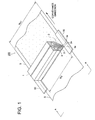
- Fig. 1 is a perspective view of the spray coating
device of a coating apparatus of this invention, to be used
for production of ink jet recording paper sheets.
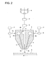
- Fig. 2 is a schematic cross-sectional view of the
coating apparatus of this invention equipped with the spray
coating device.
- Fig. 3 is an enlarged cross-sectional view explaining
the spray coating device and the shape and the spreading
condition of droplets onto the substrate.
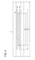
- Fig. 4 is a bottom view of the spray coating device
viewed from the coating solution discharging side.
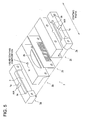
- Fig. 5 is an exploded perspective view of the spray
coating device.
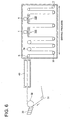
- Fig. 6 is schematic diagram showing an example of
production line of coating apparatus equipped with spray
coating devices and the coating device for the lower coating
layer located upstream of the spray coating device.
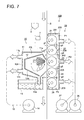
- Fig. 7 is a cross-sectional view of the coating
apparatus of this invention including the spray coating
device for production of ink jet recording sheets and the
substrate conveying apparatus.
- Fig. 8 is a frontal view of the conveying means.
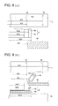
- Fig. 9(a) is a schematic plan view showing respective
width dimensions of portions of the spray coating device, the
substrate and the masking plate and Fig. 9(b) shows the
location of said dimensions as cross section A-A in Fig. 1.
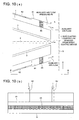
- Fig. 10(a) is a cross-sectional view showing conditions
of spray coating device equipped with auxiliary gas flow
guide plates and current plates and Fig. 10(b) is a cross
sectional view of A-A in Fig. 1.
-
DETAILED DESCRIPTION OF PREFERRED EMBODIMENT
-
Preferred embodiments to achieve the aforementioned
objective of this invention will be explained.
- (1) The coating apparatus (A) further composed of
masking plates so as to mask outer edges of the substrate,
located in a vicinity of a coating solution discharge section
of the spray coating device, wherein size of each gap between
the masking plates and the substrate is 1 to 15 mm at both
outer edges of the substrate.
- (2) The coating apparatus (A) further composed of a
second casing in which the conveying device is equipped
opposite the substrate relative to the first casing and a
pressure reducing device to maintain a reduced pressure
condition in the second casing, wherein the reduced pressure
value in the second casing is -50 to -3,000 Pa.
- (3) The coating apparatus (A), wherein the second
casing is separated into a plurality of decompression
chambers and the pressure reducing device can individually
set the reduced pressure value of each decompression chamber,
and when the reduced pressure value in the decompression
chamber at an entrance of the substrate on an upstream side
in the conveyance direction of the substrate is represented
by P1, the reduced pressure value in a middle decompression
chamber facing the spray coating device is represented by P2,
and the reduced pressure value in the decompression chamber
at an exit of the substrate on a downstream side is
represented by P3, the pressure is reduced so that
relationships of P1 < Ps <P2 and P3 < Ps < P2 are maintained.
- (4) The coating apparatus (A), wherein when an
auxiliary gas flow is discharged toward a coating section
along at least one of outermost surfaces of the spray coating
device which has the outermost surfaces on a upstream side
and a downstream side in the conveyance direction of the
substrate, and when the discharge pressure on the upstream
side in the conveyance direction of the substrate is
represented by Ph1 and the discharge pressure on the
downstream side in the conveyance direction of the substrate
is represented by Ph2, the condition of the discharge
pressure is maintained so as to satisfy the relationships of
100 Pa < Ph1 < 5,000 Pa and 100 Pa < Ph2 < 50,000 Pa.
- (5) The coating apparatus (A) composed of a guide plate
located on an outer portion of each outermost surface of the
spray coating device where the auxiliary gas flows, to make
the gas flow along the outermost surface of the spray coating
device toward the coating section without diffusion of the
gas.
- (6) The coating apparatus (A) further composed of
current plates so as to make the auxiliary gas flowing along
the outermost surfaces of the spray coating device toward the
coating section flow uniformly across a whole width of the
auxiliary gas flow.
- (7) The coating apparatus (A), wherein size of a gap
between the first casing and the substrate at the entrance
and the exit of the substrate is 1 through 10 mm.
- (8) The coating apparatus (A) further composed of
auxiliary aspiration nozzles arranged in a vicinity of the
masking plates to aspirate surplus sprayed liquid droplets.
- (9) The coating apparatus (A), wherein the masking
plates are structured of a water repellant material.
- (10) The coating apparatus (A), wherein each of the
masking plates has a decline from the center of the substrate
toward the outer edges of the substrate.
- (11) The coating apparatus (A) composed of at least one
coating solution nozzle discharging the coating solution
across the whole coating width and a plurality of gas nozzles
discharging a gas, close to an exit of the coating solution
nozzle, so as to form liquid droplets by interaction of the
gas flow with the coating solution discharged from the
coating solution nozzle.
-
-
Embodiments of this invention will be explained
referring to diagrams.
[Spray coating device]
-
Figs. 1 and 2 are perspective views of spray coating
device 1 integral in a manufacturing apparatus for ink jet
recording media and a schematic sectional view of spray
coating device 1.
-
In Fig. 1, reference numeral 1 is the spray coating
device, S is a long belt-shaped substrate. Substrate S is
conveyed in the direction indicated by an arrow in Fig. 1 at
a constant rate, employing a conveyance means (not shown).
Coating solution nozzle 2 and gas nozzle 3 of spray coating
device 1 span the full width of substrate S which is
perpendicular to the conveyance direction and are arranged so
as to face the surface to be coated of substrate S. In Fig.
2, the coating solution which is discharged from coating
solution discharge section 2a of coating solution nozzle 2,
is sprayed in the form of liquid droplets by the pressurized
gas discharged from gas discharge section 3a of gas nozzle 3,
and coating is carried out so that the droplets are deposited
on conveyed substrate S.
-
Spray coating device 1 includes a pair of gas nozzles
3, having gas pocket 3b, and coating solution nozzle 2,
having coating solution pocket 2b. A coating solution is
composed of, for example, a functional compound containing
solution, having a viscosity (preferably from 0.1 to 250
mPa·s), capable of forming liquid droplets without forming
threads. This coating solution is fed into preparation tank
4, and is subsequently supplied to coating solution pocket 2b
via pump 5 and flow meter 6, and is then led to coating
solution nozzle 2. Further, pressurized air which is fed to
pocket 3b via control valve 8 from pressurized air source 7
is supplied to gas nozzles 3.
-
During coating, the coating solution is supplied from
preparation tank 4 so that the specified coating amount is
discharged from coating solution nozzle 2. Simultaneously,
pressurized air is ejected from a pair of gas nozzles 3,
whereby the coating solution is shaped into liquid droplets
which are sprayed onto substrate S to be deposited. By
supplying the coating solution onto the surface of substrate
S in the form of minute liquid droplets, it is possible to
form, at high seed, a thin layer having markedly high
uniformity, while minimizing drying load.
-
Fig. 3 is an enlarged cross-section of the nozzle end
of spray coating device 1, showing as well the pattern of
liquid droplets formed on substrate S and the ejected state
of liquid droplets.
-
In Fig. 3, the coating solution, which is discharged
from coating solution nozzle 2, is finely divided to form
liquid particles, employing compressed air supplied from gas
nozzles 3 which are structured adjacent to both sides of
coating solution nozzle 2, whereby substantially spherical
liquid droplets 9 are formed, which subsequently are
deposited uniformly on the surface of substrate S. Fig. 3
shows a model in which substrate S is composed of support Sa
having thereon ink absorptive layer Sb, as a composition
layer. It is preferable that the spray pattern area of
liquid droplets of the coating solution, which is deposited
on substrate S, remains uniform. It is also particularly
preferable that the length in the conveyance direction
(described as length of spray in Fig. 3) remains uniform
across the coating width. Further, it is preferable that
spreading angle of the group of liquid droplets which are
sprayed toward the substrate from the opening of coating
solution nozzle 2 is uniform across the coating width.
-
Fig. 4 is a bottom view of the spray coating device 1
in Fig. 3 viewed from the coating solution discharge section
2a and shows plural end openings of coating solution
discharge section 2a aligned across the coating width, and
gas discharge section 3a.
-
Regarding coating solution discharge section 2a shown
in Fig. 4, twenty-three coating solution discharge sections
2a, having a rectangular opening, are aligned across the
coating width. The shape of the discharge section for
coating solution is not limited to being rectangular and may
also be circular. The discharge section may also be a slit
extending across the coating width. As to the size of the
end opening, 50 to 300 µm is functional and it is preferable
that the pitch (interval) is 100 to 3,000 µm. Further, gas
discharge sections 3a which extend across the coating width
are structured adjacent on both sides of coating solution
discharge sections 2a. The gas discharge section is not
limited to a slit and may be a plurality of circular or
rectangular end openings similar to the coating solution
discharge sections. When the shape of the gas discharge is
circular or rectangular, it is preferable that the size is 50
to 300 µm and the pitch is 100 to 3,000 µm. Coating solution
discharge sections 2a are arranged at equal intervals.
Similarly gas discharge sections 3a are also arranged at
equal intervals when they are circular or rectangular.
-
Herein, two gas discharge sections 3a paired with one
coating solution discharge section 2a are considered to be
aligned in the direction perpendicular to the coating width.
However, coating solution discharge sections 2a and gas
discharge sections 3a may alternatively be structured in a
zigzag pattern when the openings of gas discharge section 3a
are circular or rectangular.
-
Fig. 5 is a perspective exploded view of spray coating
device 1. In Fig. 5, reference codes 1b and 1d are die
blocks which form a coating slit of the specified length, and
allow the coating solution to flow down the aforesaid slit.
Die block 1b receives the coating solution supplied from a
coating solution supply source (not shown) and includes a
coating solution supply opening 1f which allows the coating
solution to pass into coating solution pocket 2b. The
coating solution, which is retained in coating solution
pocket 2b, flows down the coating solution slit formed
between die blocks 1b and 1d. Symbol 1c is a shim (packing
metal) interposed between block 1b and 1d which divides the
slit for the coating solution formed between die blocks 1b
and 1d in the perpendicular direction so as to form a
plurality of coating solution nozzles across the coating
width. According to the shape of the shim, the slit for the
coating solution may be changed into either circular or
rectangular openings. In the case of use of a slit extending
across the coating width, the shim (packing metal)
represented on 1c is not employed.
-
Further, 1a and 1e each is a gas block and forms a gas
nozzle via the gap with die blocks 1b and 1d respectively,
through which compressed gas passes. In such a case, the gas
nozzle is a slit which extends across the coating width.
Compressed air is supplied from an air source (not shown) to
air supply channel 1g of each gas block, and after a
temporary stay in gas pocket 3b, flows downward through the
gas nozzles formed in the gap between die blocks 1b and 1d
and gas blocks 1a and 1e respectively.
-
The coating solution, which flows down the channel
forming the coating solution nozzle, and compressed air which
flows down the two separate gas nozzles, collide just below
the coating solution discharge section 2a, which is the
bottom section of spray coating device 1, whereby liquid
droplets are formed and are deposited onto the substrate S
which is to be coated.
-
The angle of gas nozzles 3 with respect to coating
solution nozzle 2 is preferably in the range of 5 to 50
degrees. Further, it is possible to appropriately select the
distance between coating solution discharge section 2a of
spray coating device 1 and substrate S to be in the range of
about 2 to about 50 mm.
-
The supply rate of the coating solution from the
coating solution nozzle varies, since it depends on the
desired coating layer thickness, the concentration of coating
solution, the coating speed, and the like. However, the
coating amount on the substrate is preferably in the range of
about 1 to about 50 g/m2. When the coating amount is less
than 1 g/m2, it is difficult to form a uniformly stable
coating layer, while when it exceeds 50 g/m2, it becomes
difficult to exhibit the desired effects of the present
invention due to adverse effects as to a drying load. It is
characteristic that the wet layer thickness of the coating
solution is from 1 to 50 µm, and is preferably from 5 to 30
µm.
-
On the other hand, gases to be ejected from gas nozzles
3 are not particularly limited as long as they are suitable
for coating, and commonly air is employed. Gas supply
conditions are preferably in the range of about 1 to about 50
CMM/m (flow rate per coating width). In such cases, from the
viewpoint of achieving uniform coating, inner pressure in the
gas nozzles 3 is preferably at least 10 kPa.
-
The viscosity of coating solutions is preferably from
0.1 to 250 mPa·s, is preferably from 0.1 to 50 mPa·s, and is
more preferably from 0.1 to 20 mPa·s. By supplying such low
viscous coating solutions to spray coating device 1, it is
possible to achieve a spray of uniform liquid droplets across
the coating width.
-
Further, in order to achieve a spray of uniform liquid
droplets across the coating width, the surface tension of
coating solutions is adjusted from 20 to 70 mN/m, preferably
from 20 to 50 mN/m, and more preferably from 20 to 30 mN/m.
-
Still further, when liquid droplets are formed by
allowing a gas flow to collide with the coating solution
while employing spray coating devices 1, a uniform spray is
easily achieved by employing gas having an inner gas pressure
of at least 10 kPa, more preferably at least 20 kPa, and
still more preferably at least 50 kPa.
-
When employing the aforesaid means, a coating solution
is scattered in the form of discontinuous liquid droplets
across the coating width, instead of forming threads, whereby
it is possible to uniformly apply the coating solution onto
substrate S, even though the amount of the coating solution
is small. As a result, it is possible to make a uniform
coating thickness. Further, despite the supply of
discontinuous liquid droplets onto substrate S, the amount of
coating solution can be decreased to result in a minimal
drying load.
[Coating production line]
-
Fig. 6 is a schematic diagram showing one example of a
coating production line provided with spray coating device 1
downstream of an ordinary slide bead type coating device 30
of the flow rate regulating type explained above. Here,
substrate S is employed composed of a support coated with a
composition layer. After coating the aforesaid composition
layer, a plurality of spray coating devices 1 are arranged
along the drying process. Herein, forming the composition
layer, as well as coating the overcoating layer (being the
uppermost layer) according to the present invention in a
single production line, as stated above, is called "on-line
coating".
-
A support from a master roll is allowed to pass over
conveyance roller 31, employing a conveyance means (not
shown). Subsequently, during the process in which the
support is reversed via the position of back-up roller 32, a
coating solution forming a porous ink absorptive layer (a
composition layer), which is supplied from a flow rate
regulating type slide bead coating apparatus 30, is coated to
form substrate S. Since the coating solution of the porous
ink absorptive layer is composed of hydrophilic binders, the
coated support is temporarily cooled and set in cooling zone.
40.
-
Substrate S composed of the resulting support having
thereon an ink absorptive layer, is conveyed to a drying
zone. In the drying zone, there are alternately arranged
reversers 33 which achieves reversing conveyance via blown
air with no contact with the newly coated layer surface, and
an ordinary conveyance roller 34 which performs reverse
conveyance in contact with the back surface of substrate S,
whereby substrate S is conveyed. In the aforesaid drying
process, drying is carried out via blown warm air (the warm
air blowing means is not shown). On the way of the aforesaid
drying process, preferably after decreasing drying, another
coating layer is deposited via liquid droplet spraying, as
described above, employing two spray coating devices 1. It
is preferable that at least one of two spray coating devices
is arranged at or after the drying end point. Herein, two
spray coating devices are employed, however, the number of
apparatus may be only 1 or 3 or more. When coating,
employing liquid droplet spray, is performed under a
multistage system, drying load decreases, and also uniformity
of the layer thickness is enhanced, and it becomes possible
to apply a plurality of compositions which can not be mixed
simultaneously.
-
When a thin layer is formed on substrate S, employing
the coating method of the present invention, the coating
speed may not be necessarily specified, since it varies
depending on the types of coating solutions, the
concentration, the solvent content, and the drying capacity.
However, the coating speed is preferably from 50 to 300
m/min, but preferred is a coating speed of 100 to 300 m/min.
-
In the coating method of the present invention, when a
layer is applied onto substrate S comprising a support having
thereon at least one composition layer, the subsequent
coating is preferably carried out at or after the decreasing
drying of the composition layer formed on the support, and is
more preferably carried out at or after end point of the
drying process. Further, it is preferable that a coating
process in which the aforesaid composition layer is coated,
employing slide bead coating, and a coating process in which
coating is carried out employing spray coating device 1 of
the present invention are continuously performed employing a
single production line (called on-line coating).
-
Due to the relatively small drying load, it is possible
to apply the coating apparatus and the coating method of the
present invention in the drying process of the aforesaid
composition layer. Generally, in a drying process, drying is
carried out by blowing drying air, conditioned to a specified
temperature and humidity, onto the coated surface or the back
of the support to prevent cracking of the layer, while
continuously conveying a wet coated layer.
-
It becomes possible to achieve high speed thin layer
coating of uniform layer thickness and resulting in reduced
drying load by forming liquid droplets of a coating solution
across the coating width in the direction which crosses the
conveyance direction of substrate S and supplying the coating
solution onto substrate S.
-
Herein, substrate S, as described in the present
invention, refers to an object to be coated while employing
the coating method of the present invention in which coating
is carried out by spraying liquid droplets of a coating
solution, and its structure is not particularly limited. The
aforesaid long belt shaped substrates S, as well as those
including the aforesaid substrate S having thereon a
composition layer are preferred because it is possible to
efficiently achieve the desired effects of the present
invention. However, aforesaid substrates S are not limited
to those above.
-
Further, in the present invention, substrate S is
conveyed relative to coating solution discharge section 2a of
spray coating device 1, whereby continuous coating production
is performed. The coating solution discharge section 2a has
a width which is equal to or greater than the coating width
of substrate S (which refers to the length of the coating
portion of substrate S perpendicular to the conveyance
direction of the aforesaid substrate S), and is arranged so
that substrate S passes under the falling coating solution
which is then applied onto substrate S only by conveying
substrate S relative to the coating apparatus. When
substrate S is long belt-shaped, it is preferable that the
aforesaid belt-shaped substrate S itself is allowed to be
conveyed in the longitudinal direction thereof and the
coating solution discharge section 2a is positioned across
the width (the direction perpendicular to the longitudinal
direction) of aforesaid substrate S. By conveying substrate
S in one direction relative to spray coating device 1 and
spraying the coating solution across the coating width in the
form of liquid droplets, it is possible to coat a very thin
layer having a uniform layer thickness, resulting in
minimized drying load.
-
Further, across the coating width, liquid droplets,
which are sprayed from the coating
solution discharge section
2a of the
spray coating device 1, are required to satisfy the
following conditions:
- 1. The liquid droplet diameter is uniform;
- 2. The length of spray is uniform in the conveyance
direction of the area on which liquid droplets fall;
- 3. The spray angle onto substrate S is uniform; and
- 4. The deposition speed of the droplets falling onto
substrate S is uniform.
-
-
The uniform droplet diameter across the coating width,
as described herein, specifically refers to variation of the
average liquid droplet diameter of less than or equal to ±20
percent and preferably is less than or equal to ±10 percent.
-
It is possible to calculate the variation of the
average liquid droplet diameter, employing a laser
diffraction type particle size distribution measurement
apparatus (RTS51114 (a registered trademark) of Malvern
Instrument, Ltd. for example). The measurement method,
described below, is specifically used.
-
First, a coating solution is sprayed employing spray
coating device 1 which sprays the aforesaid coating solution
in the form of liquid droplets, and the state of the spray is
allowed to stabilize. Immediately after initiating spraying,
the spray state is not stabilized due to variation of the
discharge volume of the coating solution as well as variation
of gas pressure. However, it is possible to achieve stabile
while continuous spraying after a specified time.
[Coating apparatus]
-
Fig. 7 is a cross-sectional view showing coating
apparatus 100 coating a substrate to produce ink jet
recording paper sheets.
-
Coating apparatus 100 is composed of coating means 10
including spray coating device 1 and conveying means 20 to
convey substrate S.
[Coating means 10]
-
Coating means 10 is composed of first casing 10A
including spray coating device 1 and its outer casing 11 and
inner casing 12, and of waste liquid collecting means 13 and
pressure reducing means 14. Aperture area 11a located on the
right side of outer casing 11 in Fig. 7 forms gap g1 facing a
conveying passage of substrate S. Aperture areas 11b and 11c
located on the left side of outer casing 11, are connected to
pressure reducing means 14 via air suction ducts 15.
-
By activation of pressure reducing means 14, the
interior pressure of outer casing 11 is maintained at a
decompression Ps value of -50 through -3,000 Pa. The
preferable range is -100 to -2,000Pa, and more preferably -
100 to -1,000Pa.
-
Spray coating device 1 is located in inner casing 12
supported in outer casing 11. Inner casing 12 has a
shielding wall on which a mist of the coating solution is
scattered, which is ejected from coating nozzle 2 of spray
coating device 1. This coating solution spattered on the
shielding wall slides down on slope 12a and passes through
liquid waste pipe 13a to be collected by liquid waste
collecting means 13.
[Conveying means 20]
-
Conveying means 20 is located behind substrate S which
faces aperture area 11a of coating means 10. Conveying means
20 is composed of the second casing 200 forming plural
decompression chambers 201, 202 and 203 separated from each
other, and plural rollers including first feed rollers 21 and
22 located rotatably in decompression chamber (first
decompression chamber) 201 at the entrance for substrate S,
second feed rollers 24 and 25 located rotatably in
decompression chamber (third decompression chamber) 203 at
the exit of substrate S and back-up roller 23 located
rotatably in decompression chamber (second decompression
chamber) 202 facing coating solution nozzle 2 of spray
coating device 1.
-
Respective reduced pressure values P1 and P3 of
decompression chambers 201 and 203, which are connected to
pressure reducing means 26, are maintained at -50 to -3,000
Pa, when substrate S is conveyed. Reduced pressure value P2
of decompression chamber 202, which is connected to pressure
reducing means 27, is maintained at -50 to -3,000 Pa, when
substrate S is conveyed. The preferable range of pressure
values P1, P2 and P3 are -100 to -2,000 Pa, and more
preferably, are -100 to -1,000 Pa. P1, P2 and P3 are set in
this range and it is preferable to maintain the relationship
of P1, P2, P3 and Ps, as P1 < Ps < P2, and P3 < Ps <P2, and
it is preferable that, 0 < P2-Ps < 1,000 Pa, 0 < Ps-P1 <
1,000 Pa, 0 < Ps-P3 < 1,000 Pa, and more preferable that, 0 <
P2-Ps < 500 Pa, 0 < Ps-P1 < 500 Pa, 0 < Ps-P3 < 500 Pa.
-
It is preferable that gap g1 between substrate S being
in contact with circumferential surface of first feed roller
22 and the tip of aperture area 11a of outer casing 11 is
maintained at 1 to 10 mm and more preferably 1 to 5 mm. Gap
g2 between the circumferential surface of first feed rollers
21 and 22, and gap g3 between circumference surface of second
feed rollers 24 and 25 are maintained at 0.1 to 2 mm.
-
Gap g4 between partition 204 separating decompression
chambers 201 and 202, and circumferential surface of first
feed roller 22, and gap g5 between partition 205 separating
decompression chambers 202 and 203, and circumferential
surface of second feed roller 25 are also maintained at 0.1
to 2 mm.
-
In decompression chamber 201 at the entrance of sheet
conveyance, because substrate S is conveyed by rotating
second rollers 21 and 22 while being aspirated by the reduced
pressure, substrate S can be conveyed to the spray coating
section in a flat and stable condition.
-
In the spray coating section where aperture area 11a of
outer casing 11 and decompression chamber 202 face each
other, substrate S is conveyed by rotating backup roller 23
and is maintained to be stable and flat by means of pressure
reduction in outer casing 11 and in decompression chamber
202.
-
In decompression chamber 203, because substrate S is
conveyed by rotating second feed rollers 24 and 25 under
reduced pressure, substrate S after spray coating can be
conveyed in a stable and flat condition.
[Masking plate]
-
Fig. 8 is a frontal view of conveying means 20.
-
Masking plates 50 are located on both sides in the
width direction of substrate S (hatched parts in Fig. 8).
Masking plates 50 are located in the vicinity of coating
solution discharge section 2a of spray coating device 1, and
shield outer edges to form non-forming portions of coating
solution layer (refer to Figs. 1 and 8). It is preferred
that masking plates can change gap g6 and the angle relative
to substrate S. Gap g6 is preferably 1 to 15 mm, and more
preferably 1 to 10 mm, and still more preferably 1 to 5 mm.
Though the masking plates can be made of various materials,
water repellant Teflon (R) material or Teflon (R) coating
material is preferred. Auxiliary aspirating nozzles 70 are
installed near masking plates 50 to aspirate surplus
droplets. The dotted line shown in Fig. 8 represents the
locating position of spray coating device 1 facing backup
roller 23 of conveying means 20.
-
Fig. 9(a) is a schematic plan view explaining the
dimensions of the respective width of spray coating device 1,
substrate S and masking plates 50. Fig. 9(b) is cross-section
A-A of Fig. 1 and also shows the dimensions of the
respective width of spray coating device 1, substrate S and
masking plates 50.
-
The total width of spray coating device 1 is W1, the
width of liquid coating discharge section 2a of liquid
coating nozzle 2 is W2 and the width of discharge section of
gas nozzle 3 is W3 (refer to Fig. 4).
-
Substrate S has total width Ws1 and the total width of
ink absorption layer Sb is Ws2.
-
Distance W5 between masking plates 50 is arranged to be
a little less than total width Ws2 of ink absorption layer
Sb, and is arranged to be a little longer than width W2 of
coating solution discharge section 2a (Ws2 > W5 > W2).
-
Droplet particles 9 which are discharged from coating
solution discharge section 2a and are sprayed by gas nozzle 3
are scattered at an angle of , and are deposited onto
substrate S to create a uniform coating layer, while
preventing coating by masking plates 50 in the vicinity of
both edges of substrate S, effectively forming coating width
Ws3.
-
The range of conditions where the conveying condition
of the substrate and the coating condition of the substrate
are favorable were determined, regarding the coating
apparatus and the coating method of this invention, by
researching the relationship between the reduced pressure
value in the first casing containing the spray coating device
for spray-coating the substrate and the reduced pressure
value in the second casing located opposite of the substrate.
-
Optimal conditions of the gap between the masking
plates and the substrate, to provide uniform coating, was
also researched.
-
Further, the size of a gap between the masking plates
and the substrate, the angle of the masking plates relative
to the substrate and appropriateness of the plate materials
were researched.
-
Next, equalization of coating by measures to prevent
droplet scattering will be explained.
-
Specifically, auxiliary gas flow is conducted on both
the upper side and lower side of the spray coating device,
and the auxiliary gas flow is lead to the vicinity of a
coating position and auxiliary gas flow guide plates 81 are
installed so that droplets of spray coating are not widely
diffused but are lead to the coating position uniformly and
the objective to obtain coating uniformity by use of
auxiliary gas flow is achieved by optimizing gap L between
auxiliary gas flow guide plates 81 and the substrate.
-
As a specific condition range, it is preferable that
Ph1 is in the range of 100 Pa to 5,000 Pa, and more
preferably 100 Pa to 1,000 Pa, and Ph2 is preferably in the
range of 100 Pa to 50,000 Pa, and more preferably 1,000 Pa to
50,000 Pa, and still more preferably 5,000 Pa to 50,000 Pa.
When the pressure of auxiliary air flow was low, preventive
effects against scattering of droplets could not be
sufficiently achieved, and spot type defects caused by
droplets were observed on the condition when the pressure was
below 100 Pa. On the other hand, when the pressure of
auxiliary air flow was high, the auxiliary air flow disturbed
sprayed droplets and non-uniformity was caused by the air
turbulence. Because an accompanying air flow is caused by
conveyance of the substrate, liquid droplets tend to be
scattered on the downstream side of the substrate by that
influence and pressure value Ph2 should preferably be as high
as possible, but without causing spray turbulence.
Excessively large pressure value Ph1 is not preferable,
because the accompanying air flow brings the auxiliary air to
flow into the coating section and causes spray turbulence,
resulting in non-uniform coating.
-
Regarding auxiliary gas flow guide plates 81, their
existence affects the auxiliary gas flow, and without
auxiliary gas flow guide plates 81, diffusion of auxiliary
gas flow occurs and prevention of droplets from scattering
becomes insufficient.
-
It is preferable that current plates 85 are installed
into auxiliary gas flow guide plates 81. A porous material is
applied for current plates 85, such as sponge material which
allows gas to permeate through the material. Compressed air
is sent to supply port 82 via a small tube, and because it is
diffused in auxiliary gas flow guide plates 81, current
plates 85 has a large effect to equalize the air flow across
the width direction perpendicular to the conveyance
direction. Regarding current plates 85, without these,
uneven pressure distribution and occurrence of droplets were
observed on specific positions across the substrate width.
However, after installation of current plates 85, uniform
coating was obtained without droplet spotting.
-
In the coating apparatus and coating method of this
invention, a means for optimal coating conditions was sought
by pursuing measures to prevent droplet scattering.
-
These research results will be described in the
following paragraph via Examples 1 through 5.
[Example 1]
-
By means of a coating apparatus with afore-stated spray
coating device, coating was conducted while changing the
reduced pressure value of each section in various way. The
coating solution, the substrate, the coating speed and the
wet layer thickness which were employed were arranged as
follows.
-
Coating solution: liquid of 1 percentage by mass in
which water-soluble dye shown in Chem. 1 is dissolved in
water
-
Substrate: Polyethylene laminated paper made in such a
way that a support material is coated with an ink absorption
layer and dried
- Coating speed: 150m/min
- Wet layer thickness: 10µm
- Masking plate: employed
-
-
The result shown in Table 1 was obtained. The unit of
pressure in the table is Pa.
[Example 2]
-
By means of the coating apparatus with afore-stated
spray coating device, coating was conducted while changing
gap between the first casing of the spray coating device and
a substrate and also a gap between the masking plates and a
substrate. The coating solution, the substrate, the coating
speed and the wet layer thickness which were employed were as
follows. The masking plates were made of Teflon (R), however
they can also be of other material coated with Teflon(R).
-
Coating solution: liquid of 1 percentage by mass in
which water-soluble dye shown in Chem. 2 is dissolved in
water
-
Substrate: Employed was polyethylene laminated paper
made in such a way that a support material is coated with an
ink absorption layer and dried.
- Coating speed: 200m/min
- Wet layer thickness: 15 µm
- Condition of reduced pressure: In the case of P1, P3 =
-500Pa, P2 = -300Pa, and Ps = -400Pa, the results shown in
Table 2 were obtained.
- Condition of reduced pressure: In the case of P1 = P3 =
P2 = Ps = -30Pa, the results shown in Table 3 were obtained.
The unit of pressure in Table 3 is Pa.
| In the case of P1= -500Pa, P2= -300Pa, P3= -500Pa, P4= -400Pa (This invention) |
| Gap between casing of spray coating device and substrate | Gap between masking plate and substrate | Results |
| 0.5 mm | 0.5 mm | Contact of substrate with casing and masking plate caused non-stable conveyance. Slight occurrence of dust due to the contact caused new coating defects, but within allowable range. |
| 0.5 mm | 2 mm | Contact between casing and substrate caused non-stable conveyance. Slight occurrence of dust due to the contact caused new coating defects, but within allowable range. |
| 2 mm | 0.5 mm | Contact between masking plate and substrate caused non-stable conveyance. Slight occurrence of dust due to the contact caused new coating defects, but within allowable range. |
| 1 mm | 1 mm | Stable conveyance and good coating results. |
| 2 mm | 2 mm | Stable conveyance and good coating results |
| 10 mm | 10 mm | Stable conveyance and good coating results |
| 10 mm | 15 mm | Stable conveyance and good coating results |
| 12 mm | 10 mm | Reduced pressure value (PS) was non-stable and diffusion of droplets occurred causing scattered spot type defects, but within allowable range. |
| 8 mm | 17 mm | Droplets flowed under masking plates and spot type defects occurred, but within allowable range on both sides. |
| 12 mm | 17 mm | Reduced pressure value (Ps) was unstable and diffusion of droplets occurred causing scattered spot type defects across width of the substrate, but within allowable range. Liquid flowed around the edges of both plates. |
| In the case of P1= -30Pa, P2= -30Pa, P3= -30Pa, P4= -30Pa |
| Gap between casing of spray coating device and substrate | Gap between masking plate and substrate | Results |
| 0.5 mm | 0.5 mm | Spot type defects occurred without collection of uncoated droplets (NG). Contact of substrate with casing and masking plates made stable conveyance impossible. |
| 2 mm | 2 mm | Spot type defects occurred without collection of uncoated droplets (NG). |
| 10 mm | 10 mm | Spot type defects occurred without collection of uncoated droplets (NG). |
| 12 mm | 17 mm | Spot type defects occurred without collection of uncoated droplets (NG). Reduced pressure value (Ps) was unstable causing diffusion of droplets. Liquid flowed around the edges of both plates. |
-
[Example 3]
-
By means of a coating apparatus with afore-stated spray
coating device, coating was conducted in order to confirm
effectiveness of the masking plate, the change of the plate
materials, the change of the angle of the plates and
auxiliary aspiration nozzles. The coating solution, the
substrate, the coating speed and the wet layer thickness
which were employed were arranged as follows.
- Coating solution: The same coating solution as used in
examples 1 and 2
- Substrate: Polyethylene laminated paper made in such a
way that a support material is coated with an ink absorption
layer and dried
- Coating speed: 250m/min
- Wet layer thickness: 15 µm
- Condition of reduced pressure: In the case of P1, P3 =
-500Pa, P2 = -300Pa and Ps = -400Pa, the results shown in
Table 2 were obtained.
-
-
When the masking plates were removed, a thick layer was
produced on both outer edges, however there were almost no
portions which were not dried due to the thick layer.
-
Applying only masking plates made of JIS (Japanese
Industrial Standard) SUS304, parallel to the conveying
direction of a substrate at both outer edges of the substrate
allowed occasional spot type defects, but within the
allowable range, by dripping of collected liquid from the
masking plates.
-
However, by employing auxiliary aspiration nozzle 70
(illustrated in Fig. 9(b)), surplus liquid was aspirated and
spot type defects did not occur.
-
By employing water repellant material such as Teflon
(R) or a coating of Teflon (R) as water repellant treatment
for the masking plates, liquid did not collect on the masking
plates and no spot type defects occurred.
-
Further, by giving a decline to each masking plates
from the center portion toward the outer edges (approx. 10°
degree relative to substrate S), liquid did not collect on
the masking plates and no spot type defects occurred.
[Example 4]
-
By means of a coating apparatus with afore-stated spray
coating device, coating was conducted while changing
discharge pressure value (Ph) in various ways including no
pressure conditions. The coating solution, the substrate,
the coating speed, the wet layer thickness which were
employed then were arranged as follows.
- Coating solution: liquid of 1 percentage by mass in
which water-soluble dye shown in Chem. 4 is dissolved in
water
-
-
Substrate: polyethylene laminated paper made of a
support material coated with an ink absorption layer and then
dried.
- Coating speed: 200m/min
- Wet layer thickness: 15 µm
-
-
The result shown in Table 4 was obtained by employing
auxiliary gas
flow guide plates 81 and
current plates 85
illustrated in Fig. 10. The unit of pressure in the table is
Pa.
| Ph1 | Ph2 | Coating result |
| 0Pa | 0Pa | Scattering of droplets and spot type defects occurred. (Almost the whole surface, inapplicable) |
| 150Pa | 0Pa | Scattering of droplets and spot type defects occurred. (Almost the whole surface, inapplicable) |
| 0Pa | 150Pa | Scattering of droplets and spot type defects occurred. (Almost the whole surface) Much better than condition of Ph2 = 0Pa, but inapplicable. |
| 200Pa | 200Pa type | Good coating results without spot defects | This invention |
| 1,000Pa | 1,000Pa | Good coating results without spot type defects | This invention |
| 3,000Pa | 3,000Pa | Good coating results without spot type defects | This invention |
| 4,000Pa | 5,000Pa | Good coating results without spot type defects | This invention |
| 6,000Pa | 5,000Pa | Turbulence in sprayed liquid flow caused non-uniform coating (Inapplicable). |
| 8,000Pa | 5,000Pa | Turbulence in sprayed liquid flow caused non-uniform coating (Inapplicable). |
| 3,000Pa | 10,000Pa | Good coating results without spot type defects | This invention |
| 3,000Pa | 40,000Pa | Good coating results without spot type defects, but slight turbulence in sprayed liquid flow caused slight non-uniform coating (Acceptable range). | This invention |
| 3,000Pa | 60,000Pa | Turbulence in sprayed liquid flow caused excessive non-uniform coating (Inapplicable). |
| 3,000Pa | 80,000Pa | Turbulence in sprayed liquid flow caused excessive non-uniform coating (Inapplicable). |
| 7,000Pa | 80,000Pa | Turbulence in sprayed liquid flow caused excessive non-uniform coating (Inapplicable). |
[Example 5]
-
By means of a
coating apparatus 100 with afore-stated
spray coating device 1, coating was conducted while changing
the application condition of auxiliary gas
flow guide plates
81 and
current plates 85, and coating was conducted at a
discharge pressure of Ph1= 3,000Pa/30,000Pa and Ph2=
6,000Pa/60,000Pa. The coating solution, the substrate, the
coating speed, the wet layer thickness employed were arranged
as follows.
- Coating solution: The same coating solution as used in
Examples 1 to 4
- Substrate: Polyethylene laminated paper made in such a
way that a support material is coated with an ink absorption
layer and dried.
- Coating speed: 250m/min
- Wet layer thickness: 20 µm
- Auxiliary air flow pressure: 5,000Pa
-
-
The result shown in Table 5 was obtained by employing
auxiliary gas
flow guide plates 81 and
current plates 85
illustrated in Fig. 10. The unit of pressure in the table is
Pa.
| Here, App.: Applied Not: Not Applied T.I: This invention |
| Ph1 | Ph2 | Auxiliary gas flow guide plate | Current plate | Coating result |
| 3,000 | 6,000 | App. | App. | Good result without spot type defects | T.I |
| 3,000 | 6,000 | App. | Not | Spot type defects occurred on specific positions across the width of the substrate (Allowable range). | T.I |
| 3,000 | 6,000 | Not | App. | Slight droplet scattering and slight spot type defects occurred across the width of the substrate (Allowable range). | T.I |
| 3,000 | 6,000 | Not | Not | Slight droplet scattering and slight spot type defects occurred across the width of the substrate (Many in specific positions. The lowest allowable range). | T.I |
| 30,000 | 60,000 | App. | App. | Flow turbulence of spray liquid and non-uniform coating occurred (Inapplicable). |
| 30,000 | 60,000 | App. | Not | Flow turbulence of spray liquid and non-uniform coating occurred (Inapplicable). |
| 30,000 | 60,000 | Not | App. | Flow turbulence of spray liquid caused non-uniformity, and droplet scattering and spot type defects occurred on the whole surface (Inapplicable). |
| 30,000 | 60,000 | Not | Not | Flow turbulence of spray liquid caused non-uniformity, and droplet scattering and spot type defects occurred on the whole surface (Heavy occurrence only on specific positions. Inapplicable). |