EP1575654B1 - Einstellbares hydrocephalusventil - Google Patents
Einstellbares hydrocephalusventil Download PDFInfo
- Publication number
- EP1575654B1 EP1575654B1 EP03767779A EP03767779A EP1575654B1 EP 1575654 B1 EP1575654 B1 EP 1575654B1 EP 03767779 A EP03767779 A EP 03767779A EP 03767779 A EP03767779 A EP 03767779A EP 1575654 B1 EP1575654 B1 EP 1575654B1
- Authority
- EP
- European Patent Office
- Prior art keywords
- valve according
- valve
- spring
- housing
- magnets
- Prior art date
- Legal status (The legal status is an assumption and is not a legal conclusion. Google has not performed a legal analysis and makes no representation as to the accuracy of the status listed.)
- Expired - Lifetime
Links
- 208000003906 hydrocephalus Diseases 0.000 title claims abstract description 9
- 230000007246 mechanism Effects 0.000 claims abstract description 14
- 238000013461 design Methods 0.000 claims description 10
- 238000003825 pressing Methods 0.000 claims description 8
- RTAQQCXQSZGOHL-UHFFFAOYSA-N Titanium Chemical compound [Ti] RTAQQCXQSZGOHL-UHFFFAOYSA-N 0.000 claims description 5
- 239000012530 fluid Substances 0.000 claims description 5
- 210000000683 abdominal cavity Anatomy 0.000 claims description 4
- 229910052751 metal Inorganic materials 0.000 claims description 4
- 239000002184 metal Substances 0.000 claims description 4
- 239000010936 titanium Substances 0.000 claims description 4
- 229910052719 titanium Inorganic materials 0.000 claims description 4
- 230000000694 effects Effects 0.000 claims description 3
- 238000005259 measurement Methods 0.000 claims description 3
- 230000007704 transition Effects 0.000 claims description 3
- 229910001069 Ti alloy Inorganic materials 0.000 claims description 2
- 238000000926 separation method Methods 0.000 claims 6
- 238000009530 blood pressure measurement Methods 0.000 claims 1
- 210000004720 cerebrum Anatomy 0.000 claims 1
- 230000003292 diminished effect Effects 0.000 claims 1
- 230000005489 elastic deformation Effects 0.000 claims 1
- 230000002093 peripheral effect Effects 0.000 claims 1
- 238000000034 method Methods 0.000 abstract description 2
- 230000004913 activation Effects 0.000 abstract 1
- 230000009849 deactivation Effects 0.000 abstract 1
- 210000004556 brain Anatomy 0.000 description 9
- XLYOFNOQVPJJNP-UHFFFAOYSA-N water Substances O XLYOFNOQVPJJNP-UHFFFAOYSA-N 0.000 description 7
- 230000008859 change Effects 0.000 description 6
- 238000010276 construction Methods 0.000 description 6
- 229910000831 Steel Inorganic materials 0.000 description 5
- 210000001175 cerebrospinal fluid Anatomy 0.000 description 5
- 239000000463 material Substances 0.000 description 5
- 238000000465 moulding Methods 0.000 description 5
- 230000002829 reductive effect Effects 0.000 description 5
- 239000010959 steel Substances 0.000 description 5
- 230000002349 favourable effect Effects 0.000 description 4
- 210000003625 skull Anatomy 0.000 description 4
- 230000008901 benefit Effects 0.000 description 3
- 238000007373 indentation Methods 0.000 description 3
- 230000009467 reduction Effects 0.000 description 3
- 229910052594 sapphire Inorganic materials 0.000 description 3
- 239000010980 sapphire Substances 0.000 description 3
- 238000005520 cutting process Methods 0.000 description 2
- 238000006073 displacement reaction Methods 0.000 description 2
- 238000009434 installation Methods 0.000 description 2
- 238000004519 manufacturing process Methods 0.000 description 2
- 210000004303 peritoneum Anatomy 0.000 description 2
- 230000036316 preload Effects 0.000 description 2
- 230000000284 resting effect Effects 0.000 description 2
- 239000002689 soil Substances 0.000 description 2
- 238000012549 training Methods 0.000 description 2
- 206010012289 Dementia Diseases 0.000 description 1
- 208000034819 Mobility Limitation Diseases 0.000 description 1
- 206010046543 Urinary incontinence Diseases 0.000 description 1
- 208000012886 Vertigo Diseases 0.000 description 1
- 210000001015 abdomen Anatomy 0.000 description 1
- 230000001154 acute effect Effects 0.000 description 1
- 230000009286 beneficial effect Effects 0.000 description 1
- 210000000481 breast Anatomy 0.000 description 1
- 230000002490 cerebral effect Effects 0.000 description 1
- 150000001875 compounds Chemical class 0.000 description 1
- 230000003247 decreasing effect Effects 0.000 description 1
- 238000001514 detection method Methods 0.000 description 1
- 238000011161 development Methods 0.000 description 1
- 201000010099 disease Diseases 0.000 description 1
- 208000037265 diseases, disorders, signs and symptoms Diseases 0.000 description 1
- 210000002837 heart atrium Anatomy 0.000 description 1
- 238000002513 implantation Methods 0.000 description 1
- 238000007689 inspection Methods 0.000 description 1
- 239000007788 liquid Substances 0.000 description 1
- 239000007769 metal material Substances 0.000 description 1
- 229910001172 neodymium magnet Inorganic materials 0.000 description 1
- 230000003287 optical effect Effects 0.000 description 1
- 238000005457 optimization Methods 0.000 description 1
- 230000036961 partial effect Effects 0.000 description 1
- 230000000149 penetrating effect Effects 0.000 description 1
- 230000002265 prevention Effects 0.000 description 1
- 230000002441 reversible effect Effects 0.000 description 1
- 239000010979 ruby Substances 0.000 description 1
- 229910001750 ruby Inorganic materials 0.000 description 1
- 238000012216 screening Methods 0.000 description 1
- 229910000679 solder Inorganic materials 0.000 description 1
- 239000007787 solid Substances 0.000 description 1
- 238000003860 storage Methods 0.000 description 1
- 230000009897 systematic effect Effects 0.000 description 1
- 238000002560 therapeutic procedure Methods 0.000 description 1
- 210000001519 tissue Anatomy 0.000 description 1
- 238000013519 translation Methods 0.000 description 1
- 230000000007 visual effect Effects 0.000 description 1
Images


Classifications
-
- A—HUMAN NECESSITIES
- A61—MEDICAL OR VETERINARY SCIENCE; HYGIENE
- A61M—DEVICES FOR INTRODUCING MEDIA INTO, OR ONTO, THE BODY; DEVICES FOR TRANSDUCING BODY MEDIA OR FOR TAKING MEDIA FROM THE BODY; DEVICES FOR PRODUCING OR ENDING SLEEP OR STUPOR
- A61M27/00—Drainage appliance for wounds or the like, i.e. wound drains, implanted drains
- A61M27/002—Implant devices for drainage of body fluids from one part of the body to another
- A61M27/006—Cerebrospinal drainage; Accessories therefor, e.g. valves
-
- A—HUMAN NECESSITIES
- A61—MEDICAL OR VETERINARY SCIENCE; HYGIENE
- A61B—DIAGNOSIS; SURGERY; IDENTIFICATION
- A61B5/00—Measuring for diagnostic purposes; Identification of persons
- A61B5/03—Measuring fluid pressure within the body other than blood pressure, e.g. cerebral pressure ; Measuring pressure in body tissues or organs
- A61B5/031—Intracranial pressure
Definitions
- the invention relates to a percutaneously adjustable Hydrocephalusventil for pressure equalization in the skull of a Hydrocephaluspatienten by drainage of excess brain water in the peritoneum (abdominal cavity) or in the heart of the patient.
- Hydrocephalus patients have the following medical problem:
- the brain is surrounded by a special fluid - the cerebrospinal fluid.
- This brain water is formed in symmetrically arranged brain chambers, flows through channels into the outer CSF space and is resorbed there. Normally there is a balance between the amount of fluid produced and that absorbed. In the case of the disease of hydrocephalus (also called water head) just this balance is disturbed, there is no longer sufficient liquid degraded. This leads to an increase in pressure in the patient's head. In the infant, this causes the head to grow abnormally, the brain is broken down, and the patient's skull is increasingly filled with only brain water. In the adult growth of the head is no longer possible, it comes very quickly to critical pressure values. The brain is broken down (watered down). In adults, this can lead to difficulty walking, urinary incontinence and dementia.
- an artificial drainage system For the treatment of hydrocephalus, the implantation of an artificial drainage system has been proven since the 50s. Here, an artificial connection is created from the chambers in the brain to a discharge medium. Today the peritoneum (abdominal cavity) is usually chosen. Alternatively, the derivative into the atrium of the right heart is also common. Special valves have been integrated into these systems to control fluid drainage. Since the introduction of artificial drainage for hydrocephalus therapy in the early 1950's, numerous different valve systems have been proposed to optimize the treatment outcome.
- valve systems have a significantly higher opening pressure in the standing position of the patient than in the lying position. Both valve systems are now used very successfully for the treatment of hydrocephalus.
- the main problems of the known adjustable valves are in the setting accuracy and safety against unintendieres adjusting the valve system by externally applied magnetic fields. All previously available adjustable valves are based on a magnetic principle. On the valve side, magnets of different sizes are mounted on a rotatably mounted rotor. By externally generated magnetic fields, these rotors can be influenced in their position, which leads to an adjustment of a spring preload.
- valves are the Medos Codman valve.
- This valve contains a leaf spring, which rests on one side on a ruby ball, which is pressed by the leaf spring in the valve seat and on the other side on a stepped, rotatable rotor. Between these two points - approximately in the middle - the attachment of the leaf spring is arranged. If now the rotor is rotated by magnetic fields from the outside, the contact point changes and the opening characteristic of the valve is thus adjusted.
- the adjustment range is between 3 and about 20 cm water column.
- the outer diameter of the rotor is about 3 mm.
- the twisting range of this valve is 360 °.
- This valve shows the following systematic problem areas: The setting is changed unintended by external magnetic fields.
- a control of this change can only be done with the help of X-ray images. Especially for affected patients frequently necessary MRI examinations, especially for infants, thus entail the radiographic examination of the set pressure level. This is stressful for the patient and thus limits the use of this valve type.
- the adjustable SU 8 from Sophysa - a French company - is one of the well-known adjustable valves. Again, the valve side magnets are arranged on a rotatable rotor. The position of the rotor can be changed by external magnetic fields.
- the adjustment range is also between 3 to 20 cm water column.
- the adjustable rotation range is about 90 °, d. For example, if the 0 ° setting ensures the minimum pressure, the 90 ° setting will ensure the maximum pressure.
- the essential weak points of this construction are precisely in this small adjustment range, since the smaller the angle of rotation used, the lower the accuracy of such a system.
- this valve has the disadvantage that magnetic fields from the outside an unwanted rotation and adjustment of the opening characteristic to pull. In this construction, however, an X-ray inspection is not required. However, the unwanted adjustment is extremely easy to ensure, for example, by magnetic fields of headphones or simple panel magnets.
- Polaris valve Due to these known difficulties, Sophysa has recently introduced a new development, the so-called Polaris valve. This valve is similar to the known valve largely. However, a magnetically activatable locking mechanism is additionally provided, which means that only a very specific arrangement of externally mounted magnets makes a rotation of the rotor possible.
- the invention nevertheless holds to the known construction and has set itself the task of creating a valve that is easy to handle and safe.
- This valve should still have an internal, percutaneously operated adjustment, which is moved with an outboard adjustment.
- the valve pressure should be determined by a spring and the spring adjustable via an adjustment mechanism
- the adjustment mechanism has a pivoting or rotatable part that can be percutaneously pivoted or rotated by means of magnets, so that the spring is tensioned or relieved.
- the magnet part As a lock of the adjustable by the magnet part further magnets are provided, which are much weaker than the adjusting magnets, but should be sufficient to attract the adjustable part frictionally.
- this can only succeed as long as the forces acting on the adjustable part are too low for an adjustment and the magnetic forces are not completely or partially canceled by external influences. In particular, the external influence is observed. In homes in vehicles, on the phone, in a variety of life situations are the people exposed to more or less strong magnetic forces, which are sometimes even much stronger than the provided in the document weak magnets.
- a sufficient assurance is achieved with the features of the current main claim.
- a spring force is used to secure the valve position, wherein the valve housing is used as a spring.
- valve housing can have a resilient housing wall and a rotationally movable adjustment held centrally at a certain distance on the housing wall.
- the adjustment can be designed as an adjustment plate or as a one-armed or multi-armed lever, red or molded part. In the following, only spoken by Verstelleller. That includes other trainings.
- the distance to the housing wall is then selected so that the adjustment plate is pulled or pressed in the unactuated state with the outer edge against the housing wall.
- the associated voltage in the housing wall is formed when the housing wall is pressed during assembly of the adjustment plate.
- the housing wall can only partially revert to its original shape due to the adjustment plate. Due to the spring material of the housing wall, the housing wall is nevertheless endeavored to regress into the initial shape that existed prior to assembly. This causes the desired pressure of the adjusting plate on the housing wall.
- the housing wall can be straight and through the above described Deformation / indentation take a concave shape.
- the housing wall can also initially be concavely arched and experience a further inward curvature by the above-described deformation / indentation.
- the housing wall can also be originally convex and through the Deformation / indentation experienced a partial reduction in bulge or a complete reduction in bulge.
- the pressure force can be influenced by the thickness of the housing wall, by the extent of the original training, by the material of the housing wall and by the distance of the adjusting plate of the housing wall. An extensive optimization of the pressure can be achieved with a few attempts.
- the pressing force in addition to or instead of spring can also be caused by permanent magnets of the adjusting device located in the valve.
- a responsive to the magnetic fields of the permanent magnets material for the housing wall creates a contact pressure of the adjusting plate, which is a function of the power of the permanent magnet.
- a material for the housing wall steel is particularly suitable.
- a higher friction can be achieved by rough friction surfaces.
- the locking surfaces are roughened or coated with a friction-intensive material. The larger the diameter on which the friction surfaces lie on the housing wall, the greater the locking effect. Also favorable is a design in which the adjustment plate assumes a more or less pronounced U-shape in cross-section. Then, the housing wall corresponds with a provided on the outer edge of the adjusting plate annular elevation.
- a purely mechanical measuring device can be formed by an adjusting pin, which has a spring-mounted tip. By controlling the travel of the necessary counter pressure can be controlled and at the same time an excessive back pressure can be prevented.
- the electrical measuring device can, for example, use a current-carrying strain gauge.
- the strain gauge changes its resistance depending on the load, so that the current flow or the voltage changes. By measuring the change, the back pressure is measured. This can be used at the same time to give a visual and / or acoustic signal when reaching a minimum backpressure, which persists as long as the maximum backpressure is not exceeded or when the maximum back pressure is exceeded by an additional optical and / or acoustic Signal is supplemented.
- the spring member is then provided in the outer adjustment.
- the spring member consists either of a long-stroke, preloaded spring. In this adjustment, with appropriate design of the spring preload a Resiliency of the adjustment noticeably when the necessary pressure is reached at which the adjustment plate lifts off its associated friction surfaces. The permissible pressure is exceeded only when the flexibility of the outside adjustment is no longer noticeable. In between, there is a substantial compliance area in which the attending physician may be sure to be in the range of allowable pressure when handling the valve.
- a large displacement between the minimum opening position and the maximum opening position of the valve is provided. This increases the adjustment reliability and the adjustment accuracy.
- the large adjustment is reduced in a change in the spring load. That is, with a similar range of change of the spring load a larger adjustment is provided. To the extent that the adjustment becomes larger, the above reproduced danger of unwanted adjustment is reduced.
- at the same time increases the accuracy of the adjustment with increasing adjustment.
- the spring is placed so that its plane of movement is parallel to the rotation plane of the adjustment plate. In the sense of the invention, the parallelism is also given when the planes coincide.
- a spring rod application which is arranged pivotably.
- the spring bar can form a double-armed lever, one end of which is longer than the other end.
- the one end of the lever is in operative connection with a valve ball or valve flap of the valve, the other end of the lever interacts with the described adjusting mechanism or the adjusting plate.
- a sliding, known per se operative connection between the spring and the associated surface is preferably provided on the adjustment plate. That is, the spring slides on the contact surface of the adjustment plate.
- the operative connection with the valve ball or the valve flap is formed by the fact that the short end slidably presses against the valve ball or the valve flap.
- the operative connection with the adjusting mechanism with the Verstellmechnik is formed by the fact that a sliding surface for the other lever arm is provided on the rotatable or pivotable part. This sliding surface is formed as a curved path on which the spring rod slidably abuts.
- the curved path makes it possible to give the valve within wide limits an adjustable valve characteristic.
- the curved path preferably runs at least partially in a spiral shape.
- the circumferential angle of the cam track on the sliding contact surface of the adjustment plate preferably comprises at least 300 degrees, more preferably at least 340 degrees.
- valve ball or the valve flap it is important to retreat or adjust the corresponding lever arm. Or it depends on a change in the pressure force of the voltage applied to the valve ball or valve flap lever arm.
- the direction of rotation of the adjusting plate determines the pivoting direction of the lever.
- reciprocating movement of the adjusting plate also results in a reciprocating pivotal movement of the lever in the direction of a minimum opening width or a minimum closing pressure on the valve or vice versa in the direction of the maximum opening width or the maximum closing pressure.
- the adjustment plate can also be moved in the same direction and still come back to the Verstellguiding. This is achieved in that a transition is provided between the beginning of the curved path and the end of the curved path on the rotatable or pivotable adjustment plate.
- valve according to the invention can be rotated both to obtain a valve position on the shortest path to the new valve position and in the opposite direction of rotation to the end of the curved path and beyond in the new valve position.
- the latter may be desired if each valve setting should go out to control by a Verstellagging or beginning of the cam track.
- the double-armed spring lever according to the invention preferably has an angular shape.
- the two lever arms of the double-armed lever arm are at an angle to each other, which is less than 180 degrees, and may be less than 90 degrees.
- the cross section of the spring according to the invention can be arbitrary.
- Favorable are round and rectangular shapes.
- Particularly favorable is a spring with a sheet-shaped or wire-shaped cross section.
- a pin is suitable, the ends of which engage in corresponding recesses in the valve housing or in the valve cover or valve bottom.
- the ends of the pin can also be pointed, so that the pin rotates in the recesses on the tips. This procedure is technically and economically favorable.
- a weld or solder joint is suitable.
- Other compounds are also suitable.
- the spring according to the invention can readily rest on the curved path of the adjustment plate even when using a spring wire.
- Valve ball side it is beneficial if a large-area contact between the spring and the valve ball takes place.
- a sheet can be attached to the relevant spring end. The sheet is either welded or soldered or fastened in any other way.
- the required for the adjustment of the valve rotation of the adjustment plate preferably takes place by means of additional externally arranged magnets and an external rotating device.
- the magnets are preferably permanent magnets. Even more preferably, at least two magnets are diametrically opposed in the adjustment plate and at least the same number of magnets in the rotating device equally arranged opposite, wherein the magnets of the Verstellellers lie on a circular path whose diameter is equal to the diameter of the circular path on which the magnets of the rotary device are located.
- the different magnets can be brought as close to each other as possible. Due to the proximity, the magnets can develop optimal forces.
- the torques required for the generation of a torque arise when the magnets face each other with different poles, for example, with a south pole in the rotator and with a north pole in the Verstelleller.
- the rotating device is also used as an adjustment.
- a device described below is used, with which not only the rotation described above but also the pressure described above can be exercised.
- the magnets reinforce the locking by increasing the pressure and the friction between the adjustment plate and the valve housing.
- the surface closest to the magnet is preferably designed as a reactive metal surface. Particularly reactive are steel surfaces.
- the magnets are preferably small designs as pin magnets according to the claims use.
- the small magnets also contribute to small valve dimensions, as they are the subject of the claims.
- the adjusting device for the valve according to the invention can also be designed with extremely small dimensions. According to the invention, this is used to reduce the diameter of the adjustment and to a special shape of the adjustment, namely the design of the adjustment in pen form, similar to a ballpoint pen.
- the ballpoint pen-like design of the adjustment allows the handling of the adjustment as the handling of a pen or ballpoint pen, z. B by wearing in a breast pocket.
- a mechanism as in a ballpoint pen can be used to move the magnets provided on the head of the adjusting device in the longitudinal direction of the pin (with the pin against the head of the patient or against the valve) or back. In the vertical position of the pen that is a lifting and lowering.
- the inventive pin-shaped adjusting device has at the front end a cap with which the adjusting device is placed.
- the magnets automatically centering the adjustment, so that it is easy to operate the adjustment by turning.
- FIG. 1 shows a schematic cross-sectional drawing of the invention in multiple magnification.
- the valve consists of a solid Titangephaseuse 16, in which a valve spout 11 is introduced.
- the sapphire ball 5 is pressed by the leaf spring 4 in the valve seat.
- the leaf spring 4 forms with the spring wire 3 and a in FIG. 2 visible axis 15 a functional unit.
- rotor 1 Verstelleller two magnets 2 and 3 are introduced with reverse polarity.
- the rotor 1 is held on an axis 7.
- the axis 7 is located at a bottom 18 of the titanium case 16.
- the bottom 18 is curved.
- the rotor 1 is clamped with a screw 6 on the axis 7 against the lid so that a contact pressure of the rotor 1 at the bottom 18 and its elastic deflection takes place.
- the Contact pressure is such that the frictional force is sufficient to prevent rotation of the rotor 1 due to external magnetic fields.
- the bottom 18 preferably has a thickness of 0.1 to 0.2 mm, in other embodiments a thickness of up to 0.5 mm.
- the elastic deflection associated deformation is preferably 0.01 mm to about 0.1 mm, in other embodiments up to twice the soil thickness. The stronger the ground is biased, the stronger must be pressed later from the outside, to effect a lifting of the rotor 1 at 6 of the bottom 18 and cancel the locking of the rotor 1 on the bottom 18.
- the position of the rotor 1 defines the force exerted by the leaf spring 4 on the sapphire ball 5.
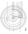
- FIG. 2 is a valve opened from below shown.
- the spring 10 which is welded to the axis 15 and the leaf spring 4.
- These components are preferably made of a metallic material, in particular of titanium or a titanium alloy.
- the spring wire of the spring 10 preferably has a diameter of 0.1 mm, in other embodiments, the spring wire may have a smaller cross section for shorter lengths and a larger cross section for larger lengths.
- the cross section of the spring wire is circular in the embodiment.
- the leaf spring preferably has a thickness of also 0.1 mm and a height of about 1 mm. For other embodiments with smaller lengths and larger lengths, the notes on the wire of the spring 10 apply accordingly.
- the leaf spring is very stiff.
- the axis 7 has in the drawing on the left a paragraph and pin, with which it projects into a smaller bore of the part 9 on the rotor 1. In the installed state, there is a gap at the point 19 between the axis 7 and the part 9.
- FIG. 1 the skin side is shown in the drawing on the right and the inside of the body in the drawing on the left. If a pressure is exerted mechanically on the bottom 18 from the outside through the skin, then the bottom 18 is deformed / curved inward depending on the force, and the axis 7 is pressed downward toward the cover 20. As a result, the gap 19 is closed, the axis 7 presses against part 9 and thus lifts off the entire rotor from the bottom 18 from. The elastic bias of the bottom 18 and the friction forces at the point 8 are canceled. Now arises at the point 8 a gap, the rotor is now freely rotatable. If the external load is removed again, the outer bottom 18 goes back to its original position and generates the elastic bias between support point 17 and support point 8. The rotor is clamped back in the housing, a rotation is not possible.
- the rotor 1 has a cam disc 13. In FIG. 2 the rotor 1 is shown in the minimum position. By rotation about 300 degrees, the spring 10 is brought at the contact point 21 corresponding to the cam 13 in its maximum position, so that the resulting opening pressure is now maximum.
- the height difference between the minimum and maximum spring deflection of part 4 or 10 is about 0.7 to 0.8 mm. In concrete terms, however, this depends on the dimension of the selected titanium wire 10.
- the arrangement of the two magnets 2 and 3 is such that an externally applied magnetic field can generate a maximum torque.
- D h.
- the distance between the two magnets is 7 mm in the embodiment, in another embodiment, 8 mm and in still other embodiments to 20mm. Specifically, this distance depends on the outer dimensions of the housing.
- the circular housing preferably has a diameter of 14mm, in other embodiments to 19mm and in still other embodiments to 31mm and is ergonomically shaped so that on the one hand the position of the valve can be well felt from the outside, but on the other hand, the overlying the valve tissue not harmed. Sharp edges are therefore avoided.
- the rotor has a tip 22, in FIG. 2 shown. This tip beats against stop 14 at the minimum value and against stop 23 at the maximum value. This stop prevents in the exemplary embodiment that maximum and minimum settings merge directly into one another and remain easily distinguishable at all times. In other embodiments, a transition is optionally provided.
- the axis 15 preferably has a diameter of 0.3 mm and may optionally have a top and bottom a tip to minimize the bearing forces. Due to the construction described a rotation of the rotor 1 is only possible if the bottom 18 pressed in the drawing to the left and the rotor 1 is thereby freely rotatable. At the same time, a specific magnetic field must be arranged from the outside in this state in order to ensure a rotation. If the soil is then relieved, the position of the rotor is elastic Clamp fixed. Now arises between the inlet 11 and the outlet 12 of the valve, a differential pressure which is greater than the opening pressure of the valve, the ball 5 is pressed from its valve seat against the leaf spring and moved in the direction of the rotor.
- the actual valve characteristic is defined by the rotational position of the rotor 1 and the resulting position of the support point 21 on the spiral or the cam 13.
- a non-linear course of the opening characteristic as a function of Rotation angle of the rotor 1 can be adjusted.
- the rotor is made so that in all initial positions of the rotor, a rotation of 10 degrees in one direction or the other, the same change in the opening pressure of the valve entails.
- the arrangement of the magnets 2 and 3 as far apart as possible has the advantage that as small as possible adjusting moments can be realized with the lowest possible magnetic forces.
- the neodymium magnets used here have a cylindrical shape with a diameter of 1 mm and a height of about 1.2 mm.
- the manufacture of housing and rotor and the production of other titanium components has the advantage of being able to set an ideal bearing clearance with precise fits and to avoid unwanted play as well as unwanted increased friction systematically.
- the axis 7 preferably has a diameter of 1 mm, the play at position 24 between the axis 7 and rotor 1 is preferably tolerated by a tight clearance fit.
- Such just a clearance fit is provided for mounting the axle 15 in the valve housing.
- This axis 15 is similar to a door hinge mounted in the valve housing and allows the almost frictionless rotation of the leaf spring 4 in the context of opening and closing the valve.
- the height of the valve is about 4.5 mm, much lower heights are not necessarily desirable, although possible, since the palpatory finding of the valve should not be too difficult.
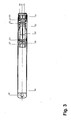
- FIG. 3 An embodiment of such a pen is in FIG. 3 shown.
- the illustration also includes a magnification over the embodiment, but less large than in Fig. 1 and 2 .
- a thin-walled tube 26 having a diameter of about 12 mm is closed at one end by a plug 25.
- a needle-bearing measuring mechanism is installed on the other side. These include: Measuring drum 28, on the surface of a scale is applied, is connected to the axis 32 which is mounted in the bearing bush 29 at the points 34 and 33. The bushing 29 is inserted into the tube 26 that a displacement and rotation of the same is not possible.
- a movable cap is inserted into the tube, which is pushed outwards by a spring force.
- the spring 30 is supported on the bearing bush 29 and presses the ring 37 against the cap 31.
- Connected to the needle 32 is the cylinder 38. Inserted in the cylinder 38 are magnets 35 and 36. In one magnet, the outside pole negative, positive for the other. The distance of the magnets corresponds approximately to the distance of the magnets within the valve, as well as the diameter.
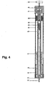
- FIG. 4 shows another embodiment of an adjusting pin.
- the dimensions correspond approximately to the dimensions of an ordinary ballpoint pen, ie, the tube has an outer diameter of preferably 12 mm and a length of about 10 cm.
- the Setting wheel 40 is firmly fixed on the axle 41. A rotation of this wheel causes a rotation of the axis.
- two magnets 50 are cylindrical in the axis. As in the valve, these magnets are polarized differently. In one magnet, the south pole is below, in the other, the north pole is below.
- the position of the two magnets on the axis corresponds to the position of the scale, which is mounted on part 47. This scaling is also fixed to the axis.
- the bushing 48 serves as a bearing for the axle 41.
- the bush is introduced by means of O-rings, through which the bushing is fixed in the sleeve 45.
- a second bearing bush is attached to the upper portion of the pin, part 42.
- axis 43 is fixed as a plain bearing in socket 42.
- the adjusting pin contains two different springs: a strong spring 44 and an extremely soft spring 46.
- the force of the spring 44 is transmitted through the axis 51 on the lower tip, which is to exert the force on the valve to be decoupled in the application.
- the diameter of the axis at the top should preferably be about 3 mm, the lower end should be dome-shaped rounded.
- the attached in the lower end of the pin cap 51 protects the storage and introduced in the axis 41 magnets 50. Through the window 53, the position of the magnets on the scale of the scale drum 47 is read.
- the proposed construction it is possible to build the adjustment conceivable small, without affecting the adjustment negative. For the first time it becomes possible to realize such adjusting pins.
- the design allows the magnets to be placed as close as possible to the skin of the patient. Under simultaneous pressure load of the valve body, a fine and precise adjustment can be made.
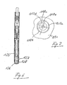
- Fig. 5 to 7 show further embodiments
- Fig. 5 shows a section through an inventive valve in an enlarged view.
- a diameter of less than 20 mm and a thickness of less than 6 mm is provided in the embodiment.
- the dimensions may be even lower in other embodiments.
- To the valve includes a steel housing, which consists of a cylindrical ring 101, a molded steel base 102 and a lid 103.
- the ring 101 is provided with an insert 104 on the inflow side.
- a valve ball 105 which seals in a valve bore 106.
- the valve ball 105 is pressed against the valve bore 106 with a wire-shaped spring.
- the spring is designed as a double-armed lever arm with a long lever arm 107a and a small / short lever arm 107b.
- the two lever arms 107a and 107b are at an acute angle to each other, because the section passes through the valve center and because the spring is shown in the area, which is behind the cutting plane in the picture and because the free end of the lever arm 107a in the area not shown runs, which lies in front of the cutting plane and because the representation of the short lever arm 107b points to a course exactly perpendicular to the plane of representation and sectional plane. In other embodiments, other angles are provided.
- the spring is soldered to a pin 109.
- the pin 109 is disposed laterally of the valve ball 105 and has two pointed ends with which it is pivotally mounted in the cylindrical ring 101.
- a plate 108 is fixed, with which the spring presses against the valve ball 105. The more the spring presses, the greater the valve resistance to the ingress of cerebrospinal fluid. The less the spring presses, the lower the valve resistance to the ingress of cerebrospinal fluid.
- the penetrating liquor passes through an outlet opening and an implanted tubing, not shown, into the abdominal cavity of the patient.
- the long lever arm 107a extends in the embodiment to the center of the cylindrical ring 101 and slides there on a curved path 110.
- the curved path is in a slot. It forms there the bottom of the slot and is part of a cylindrical shaped part 111 as Verstelleller, hereinafter referred to as a molded part.
- the one lateral boundary of the slot is formed by the cylindrical molding 111.
- the other lateral boundary of the slot is formed by a disc 112.
- Fig. 6 shows details. There, a section of the molded part 111 is shown with the cam track 110a and the lateral boundary 110b, which is formed by the molding 111 itself.
- the cam track 110a has a beginning 110d and an end 110e.
- the disc 112 sits on a shoulder of the molding 112 and is fixed there in a manner not shown.
- connection 110c is provided between the end 110e and the beginning 11d of the curved path, so that the shaped part can simply be further rotated upon reaching the end 110e in order to return to the beginning 110d.
- the molded part 111 is rotatably mounted on a bearing pin 112 and secured there with a ring 114.
- the molded part 111 has bores 115 and 116 for diametrically opposed permanent magnets.
- the permanent magnets are designed as pin magnets. Their diameter is in the embodiment at 2 mm.
- the magnets are held by cover 117 in the recesses 115 and 116. Their distance from the steel bottom 102 of the valve housing is low.
- the molded part 111 is rotated and increased or decreased as needed by the spring pressure. The adjustment takes place by rotation of the molded part 11.
- the adjusting device includes a housing 125 with a cap 126, with which the adjusting device is placed on the valve.
- a head 127 is provided with two pin magnets 128.
- the pin magnets 128 are the same distance as the magnets of the molded part 111, but are arranged so that they point to the magnets of the molded part 111 when placing the adjusting device on the valve with other poles. This will pull the magnets and follows the molded part 111 of a rotation or a pivoting movement of Verstelleinheimtung by a same direction rotation or same direction pivoting.
- the exact positioning of the adjusting device also facilitates. When lightly touched, the attraction of the magnets causes the adjustment device to be in the correct position.
- the pressing is amplified to cause a slight deformation of the valve housing.
- the housing bottom or housing cover is elastically refinedomt.
- the deformation thickness is in the exemplary embodiment 0.2 mm.
- the consequence of the deformation is a lifting of the molded part 111 from the associated friction surfaces. The friction is canceled. Accordingly easy, the molding can rotate or swing.
- a corresponding free space is created in the housing.
- a recess for the ring 114 and the bolt 113 is provided in the lid 103.
- a mechanism for pressing a mechanism is provided in the adjustment, similar to a ballpoint pen.
- the mechanism causes a resilient pressing.
- the spring secures the valve body from excessive deformation.
- the magnets can be locked with the ballpoint pen mechanism in the position required for adjusting in the cap 126 and be withdrawn after adjustment. This prevents the removal of the adjustment that unwanted further adjustment takes place by clumsy movement of the adjustment already.
- the pressing of the head 127 in the cap 126 is selected by appropriate design of the spring system so that a rotation of the housing 125 by the attending physician leads to the entrainment of the head 127.
- a guide of the head 127 is additionally or alternatively provided, which alone or together with a pressure causes the described entrainment of the head 127 upon rotation of the housing 126.
- a tongue and groove connection is provided in one embodiment, which allows the axial mobility, but causes a rotationally fixed arrangement in the circumferential direction.
Landscapes
- Health & Medical Sciences (AREA)
- Engineering & Computer Science (AREA)
- Biomedical Technology (AREA)
- Hematology (AREA)
- Animal Behavior & Ethology (AREA)
- Otolaryngology (AREA)
- Anesthesiology (AREA)
- Heart & Thoracic Surgery (AREA)
- Neurology (AREA)
- Life Sciences & Earth Sciences (AREA)
- Ophthalmology & Optometry (AREA)
- General Health & Medical Sciences (AREA)
- Public Health (AREA)
- Veterinary Medicine (AREA)
- External Artificial Organs (AREA)
- Detergent Compositions (AREA)
- Lubricants (AREA)
- Valves And Accessory Devices For Braking Systems (AREA)
- Safety Valves (AREA)
Priority Applications (1)
| Application Number | Priority Date | Filing Date | Title |
|---|---|---|---|
| CY20091100512T CY1109060T1 (el) | 2002-12-11 | 2009-05-13 | Ρυθμιζομενη βαλβιδα υδροκεφαλου |
Applications Claiming Priority (6)
| Application Number | Priority Date | Filing Date | Title |
|---|---|---|---|
| DE10258070 | 2002-12-11 | ||
| DE10258070 | 2002-12-11 | ||
| DE10347278 | 2003-10-08 | ||
| DE10347278 | 2003-10-08 | ||
| PCT/EP2003/013999 WO2004052443A1 (de) | 2002-12-11 | 2003-12-10 | Einstellbares hydrocephalusventil |
| DE102004015500A DE102004015500A1 (de) | 2002-12-11 | 2004-03-27 | Einstellbares Hydrocephalus-Ventil |
Publications (2)
| Publication Number | Publication Date |
|---|---|
| EP1575654A1 EP1575654A1 (de) | 2005-09-21 |
| EP1575654B1 true EP1575654B1 (de) | 2009-03-18 |
Family
ID=37875667
Family Applications (2)
| Application Number | Title | Priority Date | Filing Date |
|---|---|---|---|
| EP03767779A Expired - Lifetime EP1575654B1 (de) | 2002-12-11 | 2003-12-10 | Einstellbares hydrocephalusventil |
| EP05716301A Expired - Lifetime EP1613388B1 (de) | 2002-12-11 | 2005-03-22 | Einstellbares hydrocephalus-ventil |
Family Applications After (1)
| Application Number | Title | Priority Date | Filing Date |
|---|---|---|---|
| EP05716301A Expired - Lifetime EP1613388B1 (de) | 2002-12-11 | 2005-03-22 | Einstellbares hydrocephalus-ventil |
Country Status (10)
| Country | Link |
|---|---|
| US (1) | US7422566B2 (pl) |
| EP (2) | EP1575654B1 (pl) |
| JP (1) | JP4594862B2 (pl) |
| AT (1) | ATE425788T1 (pl) |
| AU (1) | AU2003292221A1 (pl) |
| DE (3) | DE10358145A1 (pl) |
| DK (1) | DK1575654T3 (pl) |
| ES (1) | ES2321085T3 (pl) |
| PL (1) | PL1613388T3 (pl) |
| WO (2) | WO2004052443A1 (pl) |
Families Citing this family (50)
| Publication number | Priority date | Publication date | Assignee | Title |
|---|---|---|---|---|
| FR2871386B1 (fr) | 2004-06-11 | 2006-09-22 | Sophysa Sa | Valve sous-cutanee |
| US7955357B2 (en) | 2004-07-02 | 2011-06-07 | Ellipse Technologies, Inc. | Expandable rod system to treat scoliosis and method of using the same |
| US20060235299A1 (en) * | 2005-04-13 | 2006-10-19 | Martinelli Michael A | Apparatus and method for intravascular imaging |
| US7334594B2 (en) * | 2005-06-29 | 2008-02-26 | Codman & Shurtleff, Inc. | Apparatus and method for adjusting a locking mechanism of a shunt valve |
| US7862502B2 (en) | 2006-10-20 | 2011-01-04 | Ellipse Technologies, Inc. | Method and apparatus for adjusting a gastrointestinal restriction device |
| DE102007059300B4 (de) | 2007-12-07 | 2022-02-10 | Christoph Miethke Gmbh & Co Kg | Einstellbares Hydrocephalus-Ventil |
| WO2009120764A2 (en) | 2008-03-25 | 2009-10-01 | Ellipse Technologies, Inc. | Systems and methods for adjusting an annuloplasty ring with an integrated magnetic drive |
| US11202707B2 (en) | 2008-03-25 | 2021-12-21 | Nuvasive Specialized Orthopedics, Inc. | Adjustable implant system |
| DE102008030942A1 (de) * | 2008-07-02 | 2010-01-07 | Christoph Miethke Gmbh & Co Kg | Hirnwasserdrainagen |
| US8382756B2 (en) | 2008-11-10 | 2013-02-26 | Ellipse Technologies, Inc. | External adjustment device for distraction device |
| US8038641B2 (en) | 2009-03-31 | 2011-10-18 | Codman & Shurtleff, Inc. | Tools and methods for programming an implantable valve |
| US9622792B2 (en) | 2009-04-29 | 2017-04-18 | Nuvasive Specialized Orthopedics, Inc. | Interspinous process device and method |
| DE102009043098B4 (de) * | 2009-09-25 | 2018-10-11 | Aesculap Ag | Schließventil für eine Körperflüssigkeiten führende Strömungsleitung |
| US8398617B2 (en) | 2009-10-30 | 2013-03-19 | Codman & Shurtleff, Inc. | Tools and methods for programming an implantable valve |
| US8591499B2 (en) | 2009-10-30 | 2013-11-26 | Medos International S.A.R.L. | Tools and methods for programming an implantable valve |
| US8518023B2 (en) * | 2009-10-30 | 2013-08-27 | Medos International S.A.R.L. | Tools and methods for programming an implantable valve |
| US8241240B2 (en) | 2009-11-09 | 2012-08-14 | Medtronic Xomed, Inc. | Adjustable valve setting with motor control |
| DE102009060533B4 (de) * | 2009-12-23 | 2019-07-11 | Christoph Miethke Gmbh & Co Kg | Implantierbares Shuntsystem |
| JP5511486B2 (ja) | 2010-04-26 | 2014-06-04 | 康雄 藍原 | 水頭症治療用シャントバルブ |
| JP5844359B2 (ja) * | 2010-06-29 | 2016-01-13 | リサーチ メディカル プロプライエタリー リミテッドResearch Medical Pty Ltd | 創傷ドレナージ制御装置 |
| US9248043B2 (en) | 2010-06-30 | 2016-02-02 | Ellipse Technologies, Inc. | External adjustment device for distraction device |
| US9149615B2 (en) | 2010-08-17 | 2015-10-06 | DePuy Synthes Products, Inc. | Method and tools for implanted device |
| US8322365B2 (en) | 2010-08-17 | 2012-12-04 | Codman & Shurtleff, Inc. | Implantable adjustable valve |
| US10675451B2 (en) | 2010-10-22 | 2020-06-09 | Christoph Miethke Gmbh & Co Kg | Hydrocephalus shunt arrangement and components thereof for draining cerebrospinal fluid in a patient having hydrocephalus |
| DE102010051743B4 (de) | 2010-11-19 | 2022-09-01 | C. Miethke Gmbh & Co. Kg | Programmierbares Hydrocephalusventil |
| WO2012112396A2 (en) | 2011-02-14 | 2012-08-23 | Ellipse Technologies, Inc. | Device and method for treating fractured bones |
| US10743794B2 (en) | 2011-10-04 | 2020-08-18 | Nuvasive Specialized Orthopedics, Inc. | Devices and methods for non-invasive implant length sensing |
| US10016220B2 (en) | 2011-11-01 | 2018-07-10 | Nuvasive Specialized Orthopedics, Inc. | Adjustable magnetic devices and methods of using same |
| US9320507B2 (en) | 2012-03-26 | 2016-04-26 | Covidien Lp | Cannula valve assembly |
| ES2881330T3 (es) | 2012-06-21 | 2021-11-29 | Medtronic Xomed Inc | Rotores e imanes con mayor resistencia a cambios de configuración inadvertidos |
| JP6253164B2 (ja) | 2012-07-23 | 2017-12-27 | アーキス バイオサイエンシーズ | シャントシステム内静水圧調整装置 |
| US10569065B2 (en) | 2012-09-11 | 2020-02-25 | Christoph Miethke Gmbh & Co Kg | Adjustable hydrocephalus valve |
| DE102012017886A1 (de) | 2012-09-11 | 2014-03-13 | C. Miethke Gmbh & Co. Kg | Einstellbares Hydrocephalus-Ventil |
| CN104902854B (zh) | 2012-10-29 | 2017-10-03 | 诺威适骨科专科公司 | 用于治疗膝盖关节炎的可调节装置 |
| US9126009B2 (en) * | 2013-03-12 | 2015-09-08 | DePuy Synthes Products, Inc. | System and method for determining position and pressure of an implantable shunt |
| US9126010B2 (en) | 2013-03-14 | 2015-09-08 | Medtronic Xomed, Inc. | Device and method for finding the center and reading the setting of an implantable medical device |
| WO2014145858A2 (en) * | 2013-03-15 | 2014-09-18 | Bitol Designs, Llc | Occlusion resistant catheter and method of use |
| FR3010636B1 (fr) | 2013-09-16 | 2015-10-02 | Sophysa Sa | Valve de drainage ajustable |
| US10751094B2 (en) | 2013-10-10 | 2020-08-25 | Nuvasive Specialized Orthopedics, Inc. | Adjustable spinal implant |
| CN111345867A (zh) | 2014-04-28 | 2020-06-30 | 诺威适骨科专科公司 | 遥控装置 |
| EP4005515B1 (en) | 2014-12-26 | 2024-07-24 | NuVasive Specialized Orthopedics, Inc. | Systems for distraction |
| US10238427B2 (en) | 2015-02-19 | 2019-03-26 | Nuvasive Specialized Orthopedics, Inc. | Systems and methods for vertebral adjustment |
| WO2017066774A1 (en) | 2015-10-16 | 2017-04-20 | Nuvasive Specialized Orthopedics, Inc. | Adjustable devices for treating arthritis of the knee |
| JP6953409B2 (ja) | 2015-12-10 | 2021-10-27 | ニューベイシブ スペシャライズド オーソペディックス,インコーポレイテッド | 伸延デバイス用の外部調整デバイス |
| DK3407812T3 (da) | 2016-01-28 | 2020-09-21 | Nuvasive Specialized Orthopedics Inc | System til knogletransport |
| US12201789B2 (en) * | 2016-05-24 | 2025-01-21 | Abbey Lenore | Ventriculostomy patch system and method |
| US12420075B2 (en) * | 2016-08-12 | 2025-09-23 | Ceredyn Biotechnology Llc | Externally programable magnetic valve assembly and controller |
| WO2018031936A1 (en) | 2016-08-12 | 2018-02-15 | Hakim Carlos | Externally programmable magnetic valve assembly and controller |
| US10799689B2 (en) * | 2017-08-24 | 2020-10-13 | Medtronic Xomed, Inc. | Method and apparatus for valve adjustment |
| CN114748786B (zh) * | 2022-03-27 | 2024-03-05 | 迈德微创(天津)医疗器械有限责任公司 | 一种具有自锁定及防归零功能的分流阀 |
Family Cites Families (17)
| Publication number | Priority date | Publication date | Assignee | Title |
|---|---|---|---|---|
| US3985140A (en) * | 1975-06-30 | 1976-10-12 | Cordis Corporation | Dual pressure valve for use in ventricular shunt system |
| US4540400A (en) * | 1983-02-17 | 1985-09-10 | Cordis Corporation | Non-invasively adjustable valve |
| CA1241246A (en) * | 1983-07-21 | 1988-08-30 | Salomon Hakim | Surgically-implantable device susceptible of noninvasive magnetic adjustment |
| US4772257A (en) * | 1983-12-08 | 1988-09-20 | Salomon Hakim | External programmer for magnetically-adjustable cerebrospinal fluid shunt valve |
| US4781673A (en) * | 1985-12-20 | 1988-11-01 | Kabushiki Kaisha Nihon M.D.M. | Brain ventricle shunt system with flow-rate switching mechanism |
| US4676772A (en) * | 1985-12-23 | 1987-06-30 | Cordis Corporation | Adjustable implantable valve having non-invasive position indicator |
| US4867740A (en) * | 1988-03-24 | 1989-09-19 | Pudenz-Schulte Medical Research Corp. | Multiple-membrane flow control valve and implantable shunt system |
| EP0617975B1 (fr) * | 1992-01-22 | 1997-08-20 | Cordis S.A. | Valve de drainage implantable pour le traitement de l'hydrocéphalie |
| DE4401422B4 (de) * | 1993-03-10 | 2004-02-05 | Christoph Miethke | Hydrocephalusventil mit zwei Ventilöffnungen |
| FR2721520B1 (fr) * | 1994-06-24 | 1996-08-30 | Sophysa Sa | Valve sous-cutanée et son dispositif de réglage externe. |
| DE19535637C2 (de) * | 1995-09-26 | 1997-10-23 | Christoph Miethke | Hydrocephalusventil |
| US5637083A (en) * | 1996-01-19 | 1997-06-10 | Pudenz-Schulte Medical Research Corporation | Implantable adjustable fluid flow control valve |
| AU1837697A (en) * | 1997-01-24 | 1998-08-18 | Medtronic Ps Medical | Implantable adjustable fluid flow control valve |
| US5928182A (en) * | 1997-07-02 | 1999-07-27 | Johnson & Johnson Professional, Inc. | Pediatric programmable hydrocephalus valve |
| FR2768057B1 (fr) * | 1997-09-10 | 1999-11-26 | Elekta Implants | Dispositif de regulation de pression pour systeme de drainage cranial externe |
| FR2816513B1 (fr) * | 2000-11-13 | 2003-03-07 | Bernard Marion | Valve sous-cutanee pour le traitement de l'hydrocephalie et ses dispositifs de reglage |
| US7390310B2 (en) * | 2002-07-10 | 2008-06-24 | Codman & Shurtleff, Inc. | Shunt valve locking mechanism |
-
2003
- 2003-12-10 JP JP2005502318A patent/JP4594862B2/ja not_active Expired - Lifetime
- 2003-12-10 DE DE10358145A patent/DE10358145A1/de not_active Withdrawn
- 2003-12-10 ES ES03767779T patent/ES2321085T3/es not_active Expired - Lifetime
- 2003-12-10 DK DK03767779T patent/DK1575654T3/da active
- 2003-12-10 DE DE50311320T patent/DE50311320D1/de not_active Expired - Lifetime
- 2003-12-10 EP EP03767779A patent/EP1575654B1/de not_active Expired - Lifetime
- 2003-12-10 AT AT03767779T patent/ATE425788T1/de active
- 2003-12-10 WO PCT/EP2003/013999 patent/WO2004052443A1/de not_active Ceased
- 2003-12-10 AU AU2003292221A patent/AU2003292221A1/en not_active Abandoned
-
2004
- 2004-03-27 DE DE102004015500A patent/DE102004015500A1/de not_active Withdrawn
-
2005
- 2005-03-22 EP EP05716301A patent/EP1613388B1/de not_active Expired - Lifetime
- 2005-03-22 WO PCT/EP2005/003052 patent/WO2005092424A1/de not_active Ceased
- 2005-03-22 PL PL05716301T patent/PL1613388T3/pl unknown
- 2005-06-10 US US11/149,928 patent/US7422566B2/en not_active Expired - Fee Related
Also Published As
| Publication number | Publication date |
|---|---|
| ATE425788T1 (de) | 2009-04-15 |
| DK1575654T3 (da) | 2009-06-02 |
| EP1613388B1 (de) | 2008-02-13 |
| DE10358145A1 (de) | 2004-07-01 |
| WO2004052443A1 (de) | 2004-06-24 |
| US20070004999A1 (en) | 2007-01-04 |
| DE102004015500A1 (de) | 2006-01-12 |
| AU2003292221A1 (en) | 2004-06-30 |
| JP2006509610A (ja) | 2006-03-23 |
| PL1613388T3 (pl) | 2008-07-31 |
| EP1575654A1 (de) | 2005-09-21 |
| ES2321085T3 (es) | 2009-06-02 |
| EP1613388A1 (de) | 2006-01-11 |
| DE50311320D1 (de) | 2009-04-30 |
| JP4594862B2 (ja) | 2010-12-08 |
| US7422566B2 (en) | 2008-09-09 |
| WO2005092424A1 (de) | 2005-10-06 |
Similar Documents
| Publication | Publication Date | Title |
|---|---|---|
| EP1575654A1 (de) | Einstellbares hydrocephalusventil | |
| DE69325384T2 (de) | Ventil zur behandlung von hydrocephalus | |
| DE69729749T2 (de) | Extrakorporales schlitzventil und steuerung für das öffnen und schliessen des schlitzes | |
| DE60315924T2 (de) | Verriegelungsmechanismus für ein Shunt-Ventil | |
| EP1343557B1 (de) | Hydrocephalusventil | |
| DE69820516T2 (de) | Vorrichtung zur Begrenzung einer Flüssigkeitsströmung | |
| US7766855B2 (en) | Adjustable hydrocephalus valve | |
| DE69720744T2 (de) | Ventil zum gebrauch mit einer intravenösen vorrichtung | |
| DE102008030942A1 (de) | Hirnwasserdrainagen | |
| DE102007059300A1 (de) | Einstellbares Hydrocephalus-Ventil | |
| EP3606597A2 (de) | Flussreduktor | |
| DE102004020071A1 (de) | Ventileinrichtung für Saug- und/oder Spülleitungen medizinischer Instrumente | |
| WO1986006970A2 (fr) | Fermeture pour tracheotomie | |
| DE69725762T2 (de) | Implantierbares,einstellbares durchflusskontrolventil | |
| DE102007017783A1 (de) | Therapiegerät | |
| EP0204986A2 (de) | Nasenolive | |
| DE102005013720A1 (de) | Einstellbares Hydrocephalusventil | |
| WO2002003860A1 (de) | Druckregulierung zur stabilisation des liquordruckes | |
| EP1450086A1 (de) | Dichtelement | |
| EP2640454B1 (de) | Elektrisch betätigbares, insbesondere programmierbares hydrocephalus-ventil | |
| DE4130601A1 (de) | Hydrocephalus-ventil | |
| DE4401422B4 (de) | Hydrocephalusventil mit zwei Ventilöffnungen | |
| WO2018184717A2 (de) | Flussreduktor | |
| DE19645725C1 (de) | Implantierbares und steuerbares Ventil für medizinische Anwendungen | |
| EP3202378B1 (de) | Orthesengelenk und orthese |
Legal Events
| Date | Code | Title | Description |
|---|---|---|---|
| PUAI | Public reference made under article 153(3) epc to a published international application that has entered the european phase |
Free format text: ORIGINAL CODE: 0009012 |
|
| 17P | Request for examination filed |
Effective date: 20050310 |
|
| AK | Designated contracting states |
Kind code of ref document: A1 Designated state(s): AT BE BG CH CY CZ DE DK EE ES FI FR GB GR HU IE IT LI LU MC NL PT RO SE SI SK TR |
|
| RAP1 | Party data changed (applicant data changed or rights of an application transferred) |
Owner name: CHRISTOPH MIETHKE GMBH & CO. KG |
|
| 17Q | First examination report despatched |
Effective date: 20061212 |
|
| GRAP | Despatch of communication of intention to grant a patent |
Free format text: ORIGINAL CODE: EPIDOSNIGR1 |
|
| GRAP | Despatch of communication of intention to grant a patent |
Free format text: ORIGINAL CODE: EPIDOSNIGR1 |
|
| GRAS | Grant fee paid |
Free format text: ORIGINAL CODE: EPIDOSNIGR3 |
|
| GRAA | (expected) grant |
Free format text: ORIGINAL CODE: 0009210 |
|
| AK | Designated contracting states |
Kind code of ref document: B1 Designated state(s): AT BE BG CH CY CZ DE DK EE ES FI FR GB GR HU IE IT LI LU MC NL PT RO SE SI SK TR |
|
| REG | Reference to a national code |
Ref country code: GB Ref legal event code: FG4D Free format text: NOT ENGLISH |
|
| REG | Reference to a national code |
Ref country code: CH Ref legal event code: EP Ref country code: CH Ref legal event code: NV Representative=s name: ROTTMANN, ZIMMERMANN + PARTNER AG |
|
| REG | Reference to a national code |
Ref country code: IE Ref legal event code: FG4D Free format text: LANGUAGE OF EP DOCUMENT: GERMAN |
|
| REF | Corresponds to: |
Ref document number: 50311320 Country of ref document: DE Date of ref document: 20090430 Kind code of ref document: P |
|
| REG | Reference to a national code |
Ref country code: GR Ref legal event code: EP Ref document number: 20090401146 Country of ref document: GR |
|
| REG | Reference to a national code |
Ref country code: SE Ref legal event code: TRGR |
|
| REG | Reference to a national code |
Ref country code: ES Ref legal event code: FG2A Ref document number: 2321085 Country of ref document: ES Kind code of ref document: T3 Ref country code: DK Ref legal event code: T3 |
|
| REG | Reference to a national code |
Ref country code: PT Ref legal event code: SC4A Free format text: AVAILABILITY OF NATIONAL TRANSLATION Effective date: 20090617 |
|
| REG | Reference to a national code |
Ref country code: PT Ref legal event code: SC4A Free format text: AVAILABILITY OF NATIONAL TRANSLATION Effective date: 20090618 |
|
| PG25 | Lapsed in a contracting state [announced via postgrant information from national office to epo] |
Ref country code: FI Free format text: LAPSE BECAUSE OF FAILURE TO SUBMIT A TRANSLATION OF THE DESCRIPTION OR TO PAY THE FEE WITHIN THE PRESCRIBED TIME-LIMIT Effective date: 20090318 Ref country code: SI Free format text: LAPSE BECAUSE OF FAILURE TO SUBMIT A TRANSLATION OF THE DESCRIPTION OR TO PAY THE FEE WITHIN THE PRESCRIBED TIME-LIMIT Effective date: 20090318 |
|
| PG25 | Lapsed in a contracting state [announced via postgrant information from national office to epo] |
Ref country code: EE Free format text: LAPSE BECAUSE OF FAILURE TO SUBMIT A TRANSLATION OF THE DESCRIPTION OR TO PAY THE FEE WITHIN THE PRESCRIBED TIME-LIMIT Effective date: 20090318 |
|
| PG25 | Lapsed in a contracting state [announced via postgrant information from national office to epo] |
Ref country code: SK Free format text: LAPSE BECAUSE OF FAILURE TO SUBMIT A TRANSLATION OF THE DESCRIPTION OR TO PAY THE FEE WITHIN THE PRESCRIBED TIME-LIMIT Effective date: 20090318 Ref country code: RO Free format text: LAPSE BECAUSE OF FAILURE TO SUBMIT A TRANSLATION OF THE DESCRIPTION OR TO PAY THE FEE WITHIN THE PRESCRIBED TIME-LIMIT Effective date: 20090318 |
|
| PLBE | No opposition filed within time limit |
Free format text: ORIGINAL CODE: 0009261 |
|
| STAA | Information on the status of an ep patent application or granted ep patent |
Free format text: STATUS: NO OPPOSITION FILED WITHIN TIME LIMIT |
|
| PG25 | Lapsed in a contracting state [announced via postgrant information from national office to epo] |
Ref country code: BG Free format text: LAPSE BECAUSE OF FAILURE TO SUBMIT A TRANSLATION OF THE DESCRIPTION OR TO PAY THE FEE WITHIN THE PRESCRIBED TIME-LIMIT Effective date: 20090618 |
|
| 26N | No opposition filed |
Effective date: 20091221 |
|
| PG25 | Lapsed in a contracting state [announced via postgrant information from national office to epo] |
Ref country code: MC Free format text: LAPSE BECAUSE OF NON-PAYMENT OF DUE FEES Effective date: 20100701 |
|
| PG25 | Lapsed in a contracting state [announced via postgrant information from national office to epo] |
Ref country code: LU Free format text: LAPSE BECAUSE OF NON-PAYMENT OF DUE FEES Effective date: 20091210 |
|
| PG25 | Lapsed in a contracting state [announced via postgrant information from national office to epo] |
Ref country code: HU Free format text: LAPSE BECAUSE OF FAILURE TO SUBMIT A TRANSLATION OF THE DESCRIPTION OR TO PAY THE FEE WITHIN THE PRESCRIBED TIME-LIMIT Effective date: 20090919 |
|
| REG | Reference to a national code |
Ref country code: CH Ref legal event code: PFA Owner name: CHRISTOPH MIETHKE GMBH & CO. KG Free format text: CHRISTOPH MIETHKE GMBH & CO. KG#ULANENWEG 2#14469 POTSDAM (DE) -TRANSFER TO- CHRISTOPH MIETHKE GMBH & CO. KG#ULANENWEG 2#14469 POTSDAM (DE) |
|
| PGFP | Annual fee paid to national office [announced via postgrant information from national office to epo] |
Ref country code: IT Payment date: 20121220 Year of fee payment: 10 |
|
| PGFP | Annual fee paid to national office [announced via postgrant information from national office to epo] |
Ref country code: NL Payment date: 20121210 Year of fee payment: 10 Ref country code: AT Payment date: 20121221 Year of fee payment: 10 |
|
| PGFP | Annual fee paid to national office [announced via postgrant information from national office to epo] |
Ref country code: CY Payment date: 20121207 Year of fee payment: 10 |
|
| PGFP | Annual fee paid to national office [announced via postgrant information from national office to epo] |
Ref country code: GR Payment date: 20131217 Year of fee payment: 11 Ref country code: TR Payment date: 20131205 Year of fee payment: 11 |
|
| PGFP | Annual fee paid to national office [announced via postgrant information from national office to epo] |
Ref country code: BE Payment date: 20131220 Year of fee payment: 11 |
|
| REG | Reference to a national code |
Ref country code: NL Ref legal event code: V1 Effective date: 20140701 |
|
| REG | Reference to a national code |
Ref country code: AT Ref legal event code: MM01 Ref document number: 425788 Country of ref document: AT Kind code of ref document: T Effective date: 20131210 |
|
| PG25 | Lapsed in a contracting state [announced via postgrant information from national office to epo] |
Ref country code: CY Free format text: LAPSE BECAUSE OF NON-PAYMENT OF DUE FEES Effective date: 20131210 Ref country code: NL Free format text: LAPSE BECAUSE OF NON-PAYMENT OF DUE FEES Effective date: 20140701 |
|
| PG25 | Lapsed in a contracting state [announced via postgrant information from national office to epo] |
Ref country code: AT Free format text: LAPSE BECAUSE OF NON-PAYMENT OF DUE FEES Effective date: 20131210 |
|
| PG25 | Lapsed in a contracting state [announced via postgrant information from national office to epo] |
Ref country code: BE Free format text: LAPSE BECAUSE OF NON-PAYMENT OF DUE FEES Effective date: 20141231 |
|
| PG25 | Lapsed in a contracting state [announced via postgrant information from national office to epo] |
Ref country code: IT Free format text: LAPSE BECAUSE OF NON-PAYMENT OF DUE FEES Effective date: 20131231 |
|
| REG | Reference to a national code |
Ref country code: GR Ref legal event code: ML Ref document number: 20090401146 Country of ref document: GR Effective date: 20150722 |
|
| PGFP | Annual fee paid to national office [announced via postgrant information from national office to epo] |
Ref country code: PT Payment date: 20150914 Year of fee payment: 13 |
|
| PG25 | Lapsed in a contracting state [announced via postgrant information from national office to epo] |
Ref country code: GR Free format text: LAPSE BECAUSE OF NON-PAYMENT OF DUE FEES Effective date: 20150722 |
|
| REG | Reference to a national code |
Ref country code: FR Ref legal event code: PLFP Year of fee payment: 13 |
|
| PG25 | Lapsed in a contracting state [announced via postgrant information from national office to epo] |
Ref country code: IT Free format text: LAPSE BECAUSE OF NON-PAYMENT OF DUE FEES Effective date: 20131210 |
|
| REG | Reference to a national code |
Ref country code: CH Ref legal event code: PCAR Free format text: NEW ADDRESS: GARTENSTRASSE 28 A, 5400 BADEN (CH) |
|
| REG | Reference to a national code |
Ref country code: FR Ref legal event code: PLFP Year of fee payment: 14 |
|
| PG25 | Lapsed in a contracting state [announced via postgrant information from national office to epo] |
Ref country code: PT Free format text: LAPSE BECAUSE OF NON-PAYMENT OF DUE FEES Effective date: 20170612 Ref country code: TR Free format text: LAPSE BECAUSE OF NON-PAYMENT OF DUE FEES Effective date: 20141210 |
|
| REG | Reference to a national code |
Ref country code: FR Ref legal event code: PLFP Year of fee payment: 15 |
|
| REG | Reference to a national code |
Ref country code: DE Ref legal event code: R082 Ref document number: 50311320 Country of ref document: DE Representative=s name: GREICHE, ALBERT, DIPL.-PHYS. DR. RER. NAT., DE Ref country code: DE Ref legal event code: R082 Ref document number: 50311320 Country of ref document: DE Representative=s name: GERLACH, TABEA, DE |
|
| REG | Reference to a national code |
Ref country code: DE Ref legal event code: R082 Ref document number: 50311320 Country of ref document: DE Representative=s name: GREICHE, ALBERT, DIPL.-PHYS. DR. RER. NAT., DE |
|
| PGFP | Annual fee paid to national office [announced via postgrant information from national office to epo] |
Ref country code: SE Payment date: 20221216 Year of fee payment: 20 Ref country code: IE Payment date: 20221207 Year of fee payment: 20 Ref country code: GB Payment date: 20221005 Year of fee payment: 20 Ref country code: FR Payment date: 20221220 Year of fee payment: 20 Ref country code: DK Payment date: 20221223 Year of fee payment: 20 Ref country code: DE Payment date: 20221231 Year of fee payment: 20 Ref country code: CZ Payment date: 20221109 Year of fee payment: 20 |
|
| PGFP | Annual fee paid to national office [announced via postgrant information from national office to epo] |
Ref country code: ES Payment date: 20230104 Year of fee payment: 20 Ref country code: CH Payment date: 20230101 Year of fee payment: 20 |
|
| REG | Reference to a national code |
Ref country code: DE Ref legal event code: R071 Ref document number: 50311320 Country of ref document: DE |
|
| REG | Reference to a national code |
Ref country code: DK Ref legal event code: EUP Expiry date: 20231210 |
|
| REG | Reference to a national code |
Ref country code: CH Ref legal event code: PL |
|
| REG | Reference to a national code |
Ref country code: ES Ref legal event code: FD2A Effective date: 20231227 |
|
| REG | Reference to a national code |
Ref country code: GB Ref legal event code: PE20 Expiry date: 20231209 |
|
| PG25 | Lapsed in a contracting state [announced via postgrant information from national office to epo] |
Ref country code: GB Free format text: LAPSE BECAUSE OF EXPIRATION OF PROTECTION Effective date: 20231209 |
|
| PG25 | Lapsed in a contracting state [announced via postgrant information from national office to epo] |
Ref country code: ES Free format text: LAPSE BECAUSE OF EXPIRATION OF PROTECTION Effective date: 20231211 |
|
| REG | Reference to a national code |
Ref country code: SE Ref legal event code: EUG |
|
| PG25 | Lapsed in a contracting state [announced via postgrant information from national office to epo] |
Ref country code: GB Free format text: LAPSE BECAUSE OF EXPIRATION OF PROTECTION Effective date: 20231209 Ref country code: ES Free format text: LAPSE BECAUSE OF EXPIRATION OF PROTECTION Effective date: 20231211 Ref country code: CZ Free format text: LAPSE BECAUSE OF EXPIRATION OF PROTECTION Effective date: 20231210 |
|
| REG | Reference to a national code |
Ref country code: IE Ref legal event code: MK9A |
|
| PG25 | Lapsed in a contracting state [announced via postgrant information from national office to epo] |
Ref country code: IE Free format text: LAPSE BECAUSE OF EXPIRATION OF PROTECTION Effective date: 20231210 |
|
| PG25 | Lapsed in a contracting state [announced via postgrant information from national office to epo] |
Ref country code: IE Free format text: LAPSE BECAUSE OF EXPIRATION OF PROTECTION Effective date: 20231210 |