EP1575407B1 - Staubsauger mit elastischer stossleiste - Google Patents
Staubsauger mit elastischer stossleiste Download PDFInfo
- Publication number
- EP1575407B1 EP1575407B1 EP03780065A EP03780065A EP1575407B1 EP 1575407 B1 EP1575407 B1 EP 1575407B1 EP 03780065 A EP03780065 A EP 03780065A EP 03780065 A EP03780065 A EP 03780065A EP 1575407 B1 EP1575407 B1 EP 1575407B1
- Authority
- EP
- European Patent Office
- Prior art keywords
- housing
- vacuum cleaner
- impact protection
- strip
- protection strip
- Prior art date
- Legal status (The legal status is an assumption and is not a legal conclusion. Google has not performed a legal analysis and makes no representation as to the accuracy of the status listed.)
- Expired - Lifetime
Links
- 230000003313 weakening effect Effects 0.000 claims description 8
- 238000010276 construction Methods 0.000 claims 2
- 239000004033 plastic Substances 0.000 description 5
- 229920003023 plastic Polymers 0.000 description 5
- 239000000463 material Substances 0.000 description 4
- 230000035939 shock Effects 0.000 description 3
- 239000004743 Polypropylene Substances 0.000 description 2
- 239000000428 dust Substances 0.000 description 2
- 229920001155 polypropylene Polymers 0.000 description 2
- 229920001871 amorphous plastic Polymers 0.000 description 1
- 229920001887 crystalline plastic Polymers 0.000 description 1
- 239000013013 elastic material Substances 0.000 description 1
- QYUQQMYTMVZNPD-UHFFFAOYSA-N hexa-3,5-dien-2-one;styrene Chemical compound CC(=O)C=CC=C.C=CC1=CC=CC=C1 QYUQQMYTMVZNPD-UHFFFAOYSA-N 0.000 description 1
- 230000001771 impaired effect Effects 0.000 description 1
- 239000004417 polycarbonate Substances 0.000 description 1
- 229920000515 polycarbonate Polymers 0.000 description 1
- -1 polypropylene Polymers 0.000 description 1
- 230000036316 preload Effects 0.000 description 1
- 238000006748 scratching Methods 0.000 description 1
- 230000002393 scratching effect Effects 0.000 description 1
- 239000007779 soft material Substances 0.000 description 1
- 230000007704 transition Effects 0.000 description 1
Images
Classifications
-
- A—HUMAN NECESSITIES
- A47—FURNITURE; DOMESTIC ARTICLES OR APPLIANCES; COFFEE MILLS; SPICE MILLS; SUCTION CLEANERS IN GENERAL
- A47L—DOMESTIC WASHING OR CLEANING; SUCTION CLEANERS IN GENERAL
- A47L9/00—Details or accessories of suction cleaners, e.g. mechanical means for controlling the suction or for effecting pulsating action; Storing devices specially adapted to suction cleaners or parts thereof; Carrying-vehicles specially adapted for suction cleaners
- A47L9/009—Carrying-vehicles; Arrangements of trollies or wheels; Means for avoiding mechanical obstacles
-
- A—HUMAN NECESSITIES
- A47—FURNITURE; DOMESTIC ARTICLES OR APPLIANCES; COFFEE MILLS; SPICE MILLS; SUCTION CLEANERS IN GENERAL
- A47L—DOMESTIC WASHING OR CLEANING; SUCTION CLEANERS IN GENERAL
- A47L5/00—Structural features of suction cleaners
- A47L5/12—Structural features of suction cleaners with power-driven air-pumps or air-compressors, e.g. driven by motor vehicle engine vacuum
- A47L5/22—Structural features of suction cleaners with power-driven air-pumps or air-compressors, e.g. driven by motor vehicle engine vacuum with rotary fans
- A47L5/36—Suction cleaners with hose between nozzle and casing; Suction cleaners for fixing on staircases; Suction cleaners for carrying on the back
- A47L5/362—Suction cleaners with hose between nozzle and casing; Suction cleaners for fixing on staircases; Suction cleaners for carrying on the back of the horizontal type, e.g. canister or sledge type
Definitions
- the invention relates to a vacuum cleaner according to the preamble of patent claim 1.
- a canister vacuum cleaner with a vacuum cleaner housing which has an outer circumferential elastic shock protection band.
- the shock protection strip consists of a strip which is attached to the vacuum cleaner housing. With its one long side of the bar opposite the vacuum cleaner housing is inclined to the outside. From the attachment point of the bar to its free longitudinal side there is an increasing distance between it and the vacuum cleaner housing.
- the impact protection strip can be made of a very strong material, since the elasticity necessary to absorb shocks is achieved by the geometric arrangement of the strip on the vacuum cleaner housing.
- a disadvantage of this bumper strip is the fact that, depending on the desired elasticity, a different type of geometric shape or arrangement of the bumper strip is required. With regard to the overall appearance of the vacuum cleaner, however, it is disadvantageous if the definition of the necessary elasticity of the impact protection strip changes the overall appearance of the vacuum cleaner.
- Another disadvantage of the impact protection strips according to the prior art is that a sharp edge is predetermined by the protruding free longitudinal side of the bumper strip, which causes scratches on these, for example, when knocked against furniture.
- the object of the invention is to provide a vacuum cleaner with a housing and a bumper strip, in which the above-mentioned disadvantages are eliminated.
- a bumper strip is to be created whose elasticity can be determined without significantly affecting the external appearance of the vacuum cleaner.
- the object of the invention is achieved in a generic vacuum cleaner characterized in that the housing has a holding element, by which the second longitudinal side of the bumper strip is held under a resilient bias against the housing.
- the holding element makes it possible to hold the projecting in a dead state from the outer surface of the housing longitudinal side under a resilient bias against the housing.
- the impact protection strip receives softer or harder spring properties. These spring properties are determined by the choice of material for the impact protection strip and by the geometry, in particular by the cross section, i. Width and height of the bumper strip, and determined by the distance between the attachment point of the bumper strip and the attachment point of the holding element. The appearance of the vacuum cleaner remains essentially unchanged despite the variation of these parameters.
- the vacuum cleaner can be operated furniture gentle.
- the elastic impact protection strip can be held on the first housing part and the second housing part can have the retaining element.
- the impact protection strip and the holding element are formed on different housing parts, the impact protection strip can be held by the holding element as soon as the two housing parts of the vacuum cleaner are mounted. The assembly of the vacuum cleaner is thereby simplified, since both the assembly of the vacuum cleaner housing and the mounting of the impact protection strip on the holding element can take place in an assembly step.
- the elastic bumper strip is formed on a lower part of the vacuum cleaner and the holding element on an upper part of the vacuum cleaner.
- the housing or the first housing part is made of plastic and the elastic impact protection strip formed thereon. The variety of parts is reduced. This has the advantage that the logistics of the assembly parts and the Assembly of the vacuum cleaner is simplified, since the bumper strip does not occur as a separate component.
- the arrangement of the impact protection strip on a lower part of the vacuum cleaner and the arrangement of the holding element on an upper part of the vacuum cleaner is particularly useful if lower part and upper part are made of different plastics. If the lower part of the vacuum cleaner is made, for example, from a semi-crystalline plastic such as polypropylene (PP), it is particularly useful to mold the bumper strip on this part, since such plastics are very tough and have high elasticity.
- PP polypropylene
- the appearance of the vacuum cleaner is essentially determined by the upper part.
- Such design parts are often intended to have a high gloss and are therefore made of an amorphous plastic such as acetyl-butadiene-styrene (ABS) or polycarbonate (PC).
- ABS acetyl-butadiene-styrene
- PC polycarbonate
- Such plastics are very brittle and have only a low elasticity.
- ABS acetyl-butadiene-styrene
- PC polycarbonate
- Such plastics are very brittle and have only a low elasticity.
- it is particularly useful to mold the retaining element In general, it is necessary to form the retaining element largely rigid so that slipping out of the elastically biased free end of the bumper strip is prevented.
- the impact protection strip has a cross section which has at least at one point of weakness compared to the other width reduced width.
- a weakening point is provided at a location which is at least in the vicinity of the transition from housing part to impact protection strip.
- the possibility is created to give the bumper strip a high elasticity, even if the housing part on which the bumper strip is formed, has only a low elasticity.
- the required elasticity of the impact protection strip is then achieved essentially by the appropriate dimensioning of the weakening point.
- the weakening point forms a film hinge over which the impact protection strip is integrally formed on the housing part.
- the elasticity of the Impact protection strip can be determined by such a weakening largely independent of the material of the housing part.
- the impact protection strip is curved convexly in its elastically biased position to the outside. Due to the convex curvature an improved scratch protection is created because when a bumping of the vacuum cleaner, for example, on furniture, the bumper strip abuts flat against the furniture and no sharp edge is present, which could cause scratches in the furniture.
- Another advantage of the buckle is that with increasing impact forces the curvature is flattened at the abutment and thus results in a larger abutment surface on the bumper strip. Thus, the forces that are generated when a violent abutment of the vacuum cleaner on the respective furniture, be distributed on a large impact surface. This additional measure prevents scratches from developing.
- the convex shape of the impact protection can be obtained by resiliently biasing a flat impact protection strip so that it bends in a gutter-like manner.
- the impact protection strip can already be preformed like a channel or with a circular section-shaped cross section.
- the bumper strip may have at least one gap-like interruption, whereby the bumper strip is divided into a number of several sections.
- the elasticity of the bumper strip is improved.
- the retaining element is formed as a protruding from the surface of the housing or the second housing part, in the direction of the bumper strip to suitable retaining strip. If the retaining element is designed as a retaining strip, then the bumper strip can be snapped in a simple manner behind the protruding from the surface of the housing retaining strip. Consequently results in a cost-effective attachment of the retaining element to the housing, or on the second housing part and the mounting of the bumper strip in its elastically biased position is easier.
- the holding element is made of plastic and integrally formed on the housing or on the second housing part.
- the retaining element or the retaining strip can be integrally formed on the second housing part.
- a simple and cost-effective attachment of the retaining element, or the retaining strip on the housing, or the second housing part is achieved.
- the holding element is designed such that it defines a receiving space with the housing, or the second housing part, in which the second longitudinal side of the impact protection strip is held.
- This receiving space is preferably notch-shaped and is bounded by an inner wall of the holding element and an outer wall of the housing, or of the second housing part. Due to the notch-shaped design of the receiving space an improved fixation of the free longitudinal side of the bumper strip is achieved.
- the second longitudinal side of the bumper strip is held under a resilient bias in a position in the receiving space in which the end of the second longitudinal side is located at a distance from the notch base of the receiving space.
- the impact protection strip is convexly convex toward the outside, it allows for additional deformation in the event of an impact. Due to the distance of the second longitudinal side of the notch base, the convexly curved impact protection strip has sufficient free space within the receiving space to deform. The impact protection strip can still deform, even if the second longitudinal side of the impact protection strip already rests against the surface of the housing. The further deformation is made possible by the fact that the second longitudinal side can be pushed further into the receiving space in the direction of the notch base with increasing impact forces. With this design, the bumper strip is reliably held by the holding element in its elastically biased position and still has a very high elasticity.
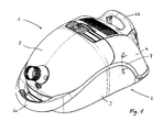
- a vacuum cleaner 1 is shown in perspective.
- the vacuum cleaner 1 has a housing 2 which is formed from a first housing part 3 and a second housing part 4.
- the first housing part 3 represents a lower shell and the second housing part 4 is an upper shell.
- a cover 5 is pivotally mounted on the upper shell (housing part 4).
- the lid 5 closes a arranged in the housing 2 dust chamber in which a dust separator, not shown, is added.
- Below the upper shell (housing part 4) an unillustrated blower unit is housed below the upper shell (housing part 4)
- a front end of the vacuum cleaner 1 has a first handle 6a.
- the handle 6a is arcuately curved and connected at its two ends to the first housing part 3.
- a second handle 6b is fixed in the region of the rear end of the vacuum cleaner 1 on the outer surface of the upper shell (housing part 4).
- the first housing part 3 and the second housing part 4 are cup-shaped and joined together along a parting line.
- a bumper strip 7 runs along the dividing line over the circumference of the housing 2.
- the impact protection strip 7 extends along an arcuate curve whose highest point is located approximately in the middle between the front and rear end of the vacuum cleaner 1. In the region of the rear end of the vacuum cleaner 1, the impact protection strip 7 extends in a deep bene near the bottom surface of the lower shell (housing part 3).
- the impact protection strip 7 has a first longitudinal side 8.
- the first longitudinal side 8 of the impact protection strip 7 is integrally formed on the first housing part 3.
- the bumper strip 7 is already preformed slightly trough-shaped curved in its dead state.
- a weakening point 9 is attached in the vicinity of the first longitudinal side 8.
- the weakening point 9 is formed by a thinning of the width of the impact protection strip 7.
- the weakening point 9 forms a film hinge, through which the impact protection strip 7 can be pivoted relative to the first housing part 3.
- the bumper strip 7 may be made of a very soft and elastic material.
- the impact protection strip 7 may be flat in the de-energized state. The convexly outwardly curved shape of the impact protection strip 7 is then obtained only when a second longitudinal side 10 of the impact protection strip 7 is held by a holding element 11 in an elastically biased position 12.
- the holding element 11 is integrally formed with its fixed end on the second housing part 4. It protrudes from the outer surface of the second housing part 4 to the outside. In the embodiment shown, the holding element 11 protrudes downwards in a diagonally downward direction. Between the outer wall of the second housing part 4 and the inner wall of the holding member 11 a notch-shaped receiving space 13 is limited. In the elastically prestressed position 12 of the impact protection strip 7, the second longitudinal side 10 of the impact protection strip 7 is located within the receiving space 13. Due to the elastic bias of the end portion of the impact protection strip 7 is located near the second longitudinal side 10 on the inner wall of the support member 11.
- the impact protection strip 7 and the holding element 11 are dimensioned in such a way and their mutual position is positioned so that a distance A is maintained between the notch base of the receiving space 13 and the second longitudinal side 10 of the impact protection strip 7. at such a design of the elastic bumper strip 7 and the support member 11, the second longitudinal side 10 of the bumper strip 7 can push in the direction of the resiliently biased position 12 in the direction of the notch base of the receiving space 13 with increasing impact forces.
- the second housing part 4 is formed as a fixed hood of the fan room of the vacuum cleaner 1.
- the second housing part 4 also form the cover 5. If the second housing part 4 forms the cover 5, then the holding element 11 is formed such that the second longitudinal side 10 of the impact protection strip 7 is surrounded by the inner wall of the holding element 11 even in the dead state of the impact protection strip 7. By closing the lid 5, the bumper strip 7 is then bent into its elastically biased position 12.
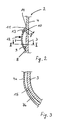
- FIG. 3 shows a longitudinal section through the impact protection strip along the section line II-II in Figure 2.
- the impact protection strip 7 is divided into a number of several sections.
- FIG. 3 shows a first section 7a and a second section 7b of the impact protection strip 7.
- the sections 7a and 7b are separated by a gap-shaped interruption 15.
- Both sections 7 a and 7 b are integrally formed on the first housing part 3.
- There may be a plurality of slit-shaped interruptions 15 distributed over the circumference of the vacuum cleaner 1 may be provided.
- Such gap-shaped interruptions 15, as shown in FIG. 3, are arranged in particular in a region in which the impact protection strip 7 turns around with a relatively small radius of curvature around the circumference of the vacuum cleaner 1.
Landscapes
- Engineering & Computer Science (AREA)
- Mechanical Engineering (AREA)
- Electric Suction Cleaners (AREA)
- Filters For Electric Vacuum Cleaners (AREA)
- Nozzles For Electric Vacuum Cleaners (AREA)
Description
- Die Erfindung betrifft einen Staubsauger gemäß dem Oberbegriff des Patentanspruchs 1.
- Aus der DE 87 11 960 U1 ist ein Bodenstaubsauger mit einem Staubsaugergehäuse bekannt, der ein außenumlaufendes elastisches Stoßschutzband aufweist. Das Stoßschutzband besteht aus einer Leiste, die an dem Staubsaugergehäuse befestigt ist. Mit ihrer einen Längsseite steht die Leiste gegenüber dem Staubsaugergehäuse schräg nach außen ab. Von der Befestigungsstelle der Leiste bis zu ihrer freien Längsseite hin besteht zwischen ihr und dem Staubsaugergehäuse ein zunehmender Abstand. Die Stoßschutzleiste kann aus einem sehr festen Material bestehen, da die zum Abfangen von Stößen notwendige Elastizität durch die geometrische Anordnung der Leiste am Staubsaugergehäuse erzielt wird. Durch die Wahl des Materials für die Leiste, durch entsprechende Bemessung ihrer Wandstärke, sowie die Lage der Anbindung und des Winkels unter dem die Leiste von der unteren Gehäusehälfte absteht, kann die Elastizität und der Federweg der Leiste beeinflusst werden. Nachteilig an dieser Stoßschutzleiste ist jedoch der Umstand, dass je nach gewünschter Elastizität eine andersartige geometrische Form oder Anordnung der Stoßschutzleiste erforderlich ist. Im Hinblick auf das Gesamterscheinungsbild des Staubsaugers ist es jedoch nachteilig, wenn durch die Festlegung der notwendigen Elastizität der Stoßschutzleiste das Gesamterscheinungsbild des Staubsaugers verändert wird.
- Ein weiterer Nachteil bei den Stoßschutzleisten gemäß dem Stand der Technik besteht darin, dass durch die abstehende freie Längsseite der Stoßschutzleiste eine scharfe Kante vorgegeben wird, die beispielsweise beim Anstoßen an Möbeln Kratzer an diesen verursacht.
- Aus der DE 8708238 U ist ein weiterer Staubsauger bekannt, der eine Stoßschutzleiste aufweist.
- Aufgabe der Erfindung ist es, einen Staubsauger mit einem Gehäuse und einer Stoßschutzleiste zu schaffen, bei dem die oben genannten Nachteile beseitigt sind. Es soll insbesondere eine Stoßschutzleiste geschaffen werden, deren Elastizität festgelegt werden kann, ohne das äußere Erscheinungsbild des Staubsaugers wesentlich zu beeinflussen.
- Die erfindungsgemäße Aufgabe wird bei einem gattungsgemäßen Staubsauger dadurch gelöst, dass das Gehäuse ein Halteelement aufweist, durch das die zweite Längsseite der Stoßschutzleiste unter einer elastischen Vorspannung gegen das Gehäuse gehalten ist. Das Halteelement ermöglicht es, die in einem spannungslosen Zustand von der äußeren Oberfläche des Gehäuses abstehende Längsseite unter einer elastischen Vorspannung gegen das Gehäuse zu halten. Je nach Größe der elastischen Vorspannung erhält die Stoßschutzleiste weichere oder härtere Federeigenschaften. Diese Federeigenschaften werden durch die Wahl des Werkstoffs für die Stoßschutzleiste und durch die Geometrie, insbesondere durch den Querschnitt, d.h. Breite und Höhe der Stoßschutzleiste, sowie durch den Abstand zwischen Befestigungsstelle der Stoßschutzleiste und der Befestigungsstelle des Haltelements bestimmt. Das äußere Erscheinungsbild des Staubsaugers bleibt trotz der Variation dieser Parameter im wesentlichen unverändert erhalten.
- In dem nicht mehr eine abstehende scharfe Kante, sondern ein flächiger Seitenabschnitt der Stoßschutzleiste den äußeren Umfang des Staubsaugers bildet, ergibt sich der zusätzliche Vorteil, dass ein Verkratzen von Möbelstücken weitgehend verhindert wird. Der Staubsauger kann dadurch möbelschonend betrieben werden.
- Ist das Gehäuse des Staubsaugers zweiteilig ausgebildet, kann , die elastische Stoßschutzleiste an dem ersten Gehäuseteil gehalten sein und das zweite Gehäuseteil das Halteelement aufweisen. In dem die Stoßschutzleiste und das Halteelement an verschiedenen Gehäuseteilen ausgebildet sind, kann die Stoßschutzleiste von dem Halteelement gehalten werden, sobald die beiden Gehäuseteile des Staubsaugers montiert sind. Die Montage des Staubsaugers wird dadurch vereinfacht, da sowohl die Montage des Staubsaugergehäuses als auch die Montage der Stoßschutzleiste an dem Halteelement in einem Montageschritt erfolgen kann.
- In einer vorteilhaften Ausgestaltung ist die elastische Stoßschutzleiste an einem Unterteil des Staubsaugers und das Halteelement an einem Oberteil des Staubsaugers ausgebildet. Vorzugsweise ist das Gehäuse beziehungsweise das erste Gehäuseteil aus Kunststoff gefertigt und die elastische Stoßschutzleiste daran angeformt. Die Teilevielfalt wird dadurch reduziert. Dies hat den Vorteil, dass die Logistik der Montageteile und die Montage des Staubsaugers vereinfacht wird, da die Stoßschutzleiste nicht als gesondertes Bauteil auftritt.
- Die Anordnung der Stoßschutzleiste an einem Unterteil des Staubsaugers und die Anordnung des Halteelements an einem Oberteil des Staubsaugers ist besonders dann sinnvoll, wenn Unterteil und Oberteil aus verschiedenen Kunststoffen hergestellt sind. Wenn das Unterteil des Staubsaugers beispielsweise aus einem teilkristallinen Kunststoff wie Polypropylen (PP) hergestellt ist, ist es besonders sinnvoll die Stoßschutzleiste an diesem Teil anzuformen, da derartige Kunststoffe sehr zäh sind und eine hohe Elastizität aufweisen.
- Üblicherweise wird das Erscheinungsbild des Staubsaugers im wesentlichen durch das Oberteil bestimmt. Derartige Designteile sollen häufig einen hohen Glanz aufweisen und werden deshalb aus einem amorphen Kunststoff wie zum Beispiel Acetyl-Butadien-Styrol (ABS) oder Polycarbonat (PC) hergestellt. Solche Kunststoffe sind sehr spröde und weisen nur eine geringe Elastizität auf. An derartigen harten und wenig flexiblen Bauteilen ist es besonders sinnvoll, das Halteelement anzuformen. Im allgemeinen ist es nötig das Halteelement weitgehend steif auszubilden, damit ein Herausrutschen des elastisch vorgespannten freien Endes der Stoßschutzleiste verhindert ist. Andererseits ist es vorteilhaft die hohe Elastizität des Unterteils zu nutzen, um eine daran angeformte Stoßschutzleiste hoher Elastizität zu erhalten.
- Ergänzend oder ersatzweise zur inneren Elastizität der Stoßschutzleiste kann es sinnvoll sein, wenn die Stoßschutzleiste einen Querschnitt aufweist, der zumindest an einer Schwächungsstelle eine gegenüber der übrigen Breite verringerte Breite aufweist. Vorzugsweise wird eine solche Schwächungsstelle an einer Stelle vorgesehen, die zumindest in Nähe des Übergangs von Gehäuseteil zu Stoßschutzleiste liegt.
- Durch diese Alternative ist die Möglichkeit geschaffen, der Stoßschutzleiste eine hohe Elastizität zu geben, selbst wenn das Gehäuseteil, an dem die Stoßschutzleiste angeformt ist, nur eine geringe Elastizität aufweist. Die benötigte Elastizität der Stoßschutzleiste wird dann im Wesentlichen durch die geeignete Dimensionierung der Schwächungsstelle erreicht. Die Schwächungsstelle bildet dabei ein Filmscharnier über das die Stoßschutzleiste beweglich an dem Gehäuseteil angeformt ist. Die Elastizität der Stoßschutzleiste kann durch eine derartige Schwächungsstelle weitgehend unabhängig von dem Material des Gehäuseteils festgelegt werden.
- In einer bevorzugten Ausgestaltung der Erfindung ist die Stoßschutzleiste in ihrer elastisch vorgespannten Position konvex nach außen gewölbt. Aufgrund der konvexen Wölbung wird ein verbesserter Kratzschutz geschaffen, da bei einem Anstoßen des Staubsaugers bspw. an Möbeln, die Stoßschutzleiste flächig an dem Möbelstück anstößt und keine scharfe Kante vorhanden ist, die Kratzer in den Möbeln verursachen könnte. Ein weiterer Vorteil der Wölbung ist es, dass bei zunehmenden Anstoßkräften die Wölbung an der Anstoßstelle abgeflacht wird und sich somit eine größere Anstoßfläche an der Stoßschutzleiste ergibt. So können die Kräfte, die bei einem heftigen Anstoßen des Staubsaugers an dem jeweiligen Möbel entstehen, auf eine große Anstoßfläche verteilt werden. Durch diese zusätzliche Maßnahme wird verhindert, dass Kratzer entstehen. Die konvexe Form der Stoßschutzleichte kann dadurch erhalten werden, dass eine flache Stoßschutzleiste derart elastisch vorgespannt wird, dass sie sich rinnenartig biegt. Alternativ kann die Stoßschutzleiste bereits rinnenartig oder mit einem kreisabschnittsförmigen Querschnitt vorgeformt sein.
- Läuft die Stoßschutzleiste zumindest über einen Teil des Umfangs des Gehäuses um, so kann die Stoßschutzleiste mindestens eine spaltartige Unterbrechung aufweisen, wodurch die Stoßschutzleiste in eine Anzahl von mehreren Abschnitten geteilt wird. Durch das Aufteilen einer umlaufenden Stoßschutzleiste in eine Anzahl von mehreren Abschnitten wird die Elastizität der Stoßschutzleiste verbessert. Insbesondere wenn die Stoßschutzleiste um eine Ecke am Umfang des Staubsaugergehäuses umläuft, kann es sinnvoll sein an dieser Stelle die Stoßschutzleiste in eine Anzahl von mehreren Abschnitten aufzuteilen. Dadurch wird verhindert, dass im Bereich der Ecke aufgrund des stark gebogenen Verlaufes der Stoßschutzleiste, die elastischen Eigenschaften beeinträchtigt werden.
- In einer bevorzugten Ausgestaltung ist das Halteelement als eine von der Oberfläche des Gehäuses bzw. des zweiten Gehäuseteils herausragende, in Richtung auf die Stoßschutzleiste zu geeignete Halteleiste ausgebildet. Wenn das Halteelement als Halteleiste ausgebildet ist, so kann die Stoßschutzleiste in einfacher Weise hinter die von der Oberfläche des Gehäuses herausragende Halteleiste eingeschnappt werden. Somit ergibt sich eine kostengünstige Befestigung des Halteelements an dem Gehäuse, bzw. an dem zweiten Gehäuseteil und die Montage der Stoßschutzleiste in ihre elastisch vorgespannte Lage ist einfacher möglich.
- Vorzugsweise ist das Halteelement aus Kunststoff gefertigt und am Gehäuse bzw. am zweiten Gehäuseteil angeformt. Analog zur angeformten Ausbildung der Stoßschutzleiste an dem ersten Gehäuseteil, kann das Halteelement, bzw. die Halteleiste am zweiten Gehäuseteil angeformt sein. Dadurch wird eine einfache und kostengünstige Befestigung des Halteelements, bzw. der Halteleiste an dem Gehäuse, bzw. dem zweiten Gehäuseteil erreicht. So kann auf gesonderte Befestigungsmittel für das Halteelement verzichtet werden.
- Vorzugsweise ist das Halteelement derart ausgebildet, dass es mit dem Gehäuse, bzw. dem zweiten Gehäuseteil einen Aufnahmeraum begrenzt, in dem die zweite Längsseite der Stoßschutzleiste gehalten ist. Dieser Aufnahmeraum ist vorzugsweise kerbenförmig ausgebildet und wird durch eine Innenwand des Halteelements und eine Außenwand des Gehäuses, bzw. des zweiten Gehäuseteiles begrenzt. Aufgrund der kerbenförmigen Ausbildung des Aufnahmeraumes wird eine verbesserte Fixierung der freien Längsseite der Stoßschutzleiste erreicht.
- Vorzugsweise ist die zweite Längsseite der Stoßschutzleiste unter einer elastischen Vorspannung in einer Position im Aufnahmeraum gehalten, in der sich das Ende der zweiten Längsseite in einem Abstand von dem Kerbgrund des Aufnahmeraumes befindet. Wenn die Stoßschutzleiste konvex nach außen gewölbt ausgebildet ist, so lässt sie im Falle eines Anstoßes eine zusätzliche Verformung zu. Aufgrund des Abstandes der zweiten Längsseite vom Kerbgrund besitzt die konvex gewölbte Stoßschutzleiste innerhalb des Aufnahmeraumes genügend Freiraum, um sich zu verformen. Die Stoßschutzleiste kann sich noch verformen, selbst wenn die zweite Längsseite der Stoßschutzleiste bereits an der Oberfläche des Gehäuses anliegt. Die weitere Verformung wird dadurch ermöglicht, dass die zweite Längsseite sich bei zunehmendem Anstoßkräften weiter in den Aufnahmeraum in Richtung des Kerbgrundes hineinschieben lässt. Durch diese Ausbildung ist die Stoßschutzleiste von dem Halteelement in ihrer elastisch vorgespannten Position zuverlässig gehalten und verfügt trotzdem über eine sehr hohe Elastizität.
- Die Erfindung ist im Folgenden anhand eines Ausführungsbeispieles näher erläutert.
- Es zeigen:
- Figur 1
- Einen Staubsauger mit einer erfindungsgemäßen Stoßschutzleiste;
- Figur 2
- einen Querschnitt durch die Stoßschutzleiste entlang der Schnittlinie I-I in Figur 1;
- Figur 3
- einen Längsschnitt durch die Stoßschutzleiste entlang der Schnittlinie II-II in Figur 2.
- In der Figur 1 ist ein Staubsauger 1 perspektivisch dargestellt. Der Staubsauger 1 weist ein Gehäuse 2 auf, das aus einem ersten Gehäuseteil 3 und einem zweiten Gehäuseteil 4 gebildet wird. Das erste Gehäuseteil 3 stellt eine Unterschale und das zweite Gehäuseteil 4 eine Oberschale dar. Ein Deckel 5 ist schwenkbar an der Oberschale (Gehäuseteil 4) gelagert. Der Deckel 5 verschließt einen im Gehäuse 2 angeordneten Staubraum, in dem ein nicht gezeigter Staubabscheider aufgenommen ist. Unterhalb der Oberschale (Gehäuseteil 4) ist ein nicht dargestelltes Gebläseaggregat untergebracht.
- Ein vorderes Ende des Staubsaugers 1 weist einen ersten Handgriff 6a auf. Der Handgriff 6a ist bogenförmig gekrümmt und an seinen beiden Enden mit dem ersten Gehäuseteil 3 verbunden. Ein zweiter Handgriff 6b ist im Bereich des hinteren Endes des Staubsaugers 1 an der äußeren Oberfläche der Oberschale (Gehäuseteil 4) befestigt. Das erste Gehäuseteil 3 und das zweite Gehäuseteil 4 sind schalenförmig ausgebildet und entlang einer Trennlinie aneinandergefügt.
- Eine Stoßschutzleiste 7 verläuft entlang der Trennlinie über den Umfang des Gehäuses 2 um. An den beiden gegenüberliegenden Seiten des Staubsaugers 1 verläuft die Stoßschutzleiste 7 entlang einer bogenförmigen Kurve, deren höchster Punkt sich etwa in der Mitte zwischen dem vorderen und hinteren Ende des Staubsaugers 1 befindet. Im Bereich des hinteren Endes des Staubsaugers 1 verläuft die Stoßschutzleiste 7 in einer tiefen bene nahe der Bodenfläche der Unterschale (Gehäuseteil 3).
- Die Figur 2 zeigt einen Ausschnitt des Querschnitts durch die Stoßschutzleiste entlang der Schnittlinie 1-1 aus Figur 1. Der Ausschnitt aus dem Gehäuse 2 ist im Bereich der Trennlinie dargestellt, an der das untere erste Gehäuseteil 3 und das obere zweite Gehäuseteil 4 aufeinandertreffen. Die Stoßschutzleiste 7 weist eine erste Längsseite 8 auf. Die erste Längsseite 8 der Stoßschutzleiste 7 ist an dem ersten Gehäuseteil 3 angeformt.
- Die Stoßschutzleiste 7 ist in ihrem spannungslosen Zustand bereits leicht rinnenartig gewölbt vorgeformt. An der Verbindungsstelle zwischen der Stoßschutzleiste 7 und dem ersten Gehäuseteil 3 ist in Nähe der ersten Längsseite 8 eine Schwächungsstelle 9 angebracht. Die Schwächungsstelle 9 wird durch eine Ausdünnung der Breite der Stoßschutzleiste 7 gebildet. Die Schwächungsstelle 9 bildet ein Filmscharnier, durch das die Stoßschutzleiste 7 gegenüber dem ersten Gehäuseteil 3 verschwenkt werden kann.
- Alternativ kann die Stoßschutzleiste 7 aus einem sehr weichen und elastischem Material hergestellt sein. In diesem Fall kann die Stoßschutzleiste 7 im spannungslosen Zustand eben ausgebildet sein. Die konvex nach außen gewölbte Form der Stoßschutzleiste 7 ergibt sich dann erst, wenn eine zweite Längsseite 10 der Stoßschutzleiste 7 durch ein Halteelement 11 in einer elastisch vorgespannten Position 12 gehalten ist.
- Das Halteelement 11 ist mit seinem festen Ende an dem zweiten Gehäuseteil 4 angeformt. Es ragt von der äußeren Oberfläche des zweiten Gehäuseteils 4 nach außen ab. In der gezeigten Ausführungsform ragt das Halteelement 11 dachgiebelförmig in einer diagonalen Richtung nach unten. Zwischen der Außenwand des zweiten Gehäuseteils 4 und der Innenwand des Halteelements 11 wird ein kerbenförmiger Aufnahmeraum 13 begrenzt. In der elastisch vorgespannten Position 12 der Stoßschutzleiste 7 befindet sich die zweite Längsseite 10 der Stoßschutzleiste 7 innerhalb des Aufnahmeraumes 13. Aufgrund der elastischen Vorspannung liegt der Endbereich der Stoßschutzleiste 7 nahe der zweiten Längsseite 10 an der Innenwand des Halteelements 11 an.
- Die Stoßschutzleiste 7 und das Halteelement 11 sind derart dimensioniert und ihre gegenseitige Lage so positioniert, dass zwischen dem Kerbgrund des Aufnahmeraums 13 und der zweiten Längsseite 10 der Stoßschutzleiste 7 ein Abstand A erhalten bleibt. Bei einer solchen Ausbildung der elastischen Stoßschutzleiste 7 und des Halteelements 11 kann sich die zweite Längsseite 10 der Stoßschutzleiste 7 bei Zunahme der Stoßkräfte in Richtung der elastisch vorgespannten Position 12 in Richtung in den Kerbgrund des Aufnahmeraums 13 hineinschieben.
- Im gezeigten Ausführungsbeispiel ist das zweite Gehäuseteil 4 als fest montierte Haube des Gebläseraums des Staubsaugers 1 ausgebildet. Alternativ oder zusätzlich kann das zweite Gehäuseteil 4 auch den Deckel 5 bilden. Wenn das zweite Gehäuseteil 4 den Deckel 5 bildet, dann ist das Halteelement 11 derart ausgebildet, dass die zweite Längsseite 10 der Stoßschutzleiste 7 auch im spannungslosen Zustand der Stoßschutzleiste 7 von der Innenwand des Halteelements 11 umfangen wird. Durch schließen des Deckels 5 wird dann die Stoßschutzleiste 7 in ihre elastisch vorgespannte Position 12 gebogen.
- Figur 3 zeigt einen Längsschnitt durch die Stoßschutzleiste entlang der Schnittlinie II-II in Figur 2. Im dargestellten Ausführungsbeispiel ist die Stoßschutzleiste 7 in eine Anzahl von mehreren Abschnitten aufgeteilt. Die Figur 3 zeigt einen ersten Abschnitt 7a und einen zweiten Abschnitt 7b der Stoßschutzleiste 7. Die Abschnitte 7a und 7b sind durch eine spaltförmige Unterbrechung 15 getrennt. Beide Abschnitte 7a und 7b sind an dem ersten Gehäuseteil 3 angeformt. Es können eine Vielzahl von spaltförmigen Unterbrechungen 15 über den Umfang des Staubsaugers 1 verteilt vorgesehen sein. Derartige spaltförmige Unterbrechungen 15, wie in Figur 3 gezeigt, sind insbesondere in einem Bereich angeordnet, in dem die Stoßschutzleiste 7 mit einem relativ kleinen Krümmungsradius um den Umfang des Staubsaugers 1 urnläuft.
Claims (12)
- Staubsauger mit einem Gehäuse (2) und einer elastischen, zwei Längsseiten (8,10) aufweisenden Stoßschutzleiste (7), die zumindest abschnittsweise am Umfang des Gehäuses (2) angeordnet ist und mit der ersten Längsseite (8) an dem Gehäuse (2) gehalten ist und deren zweite Längsseite (10) in einem spannungslosen Zustand von der äußeren Oberfläche des Gehäuses (2) absteht, dadurch gekennzeichnet, dass das Gehäuse (2) ein Halteelement (11) aufweist, durch das die zweite Längsseite (10) der Stoßschutzleiste (7) unter einer elastischen Vorspannung gegen das Gehäuse (2) gehalten ist.
- Staubsauger nach Anspruch 1, dadurch gekennzeichnet, dass das Gehäuse (2) zweiteilig ausgebildet ist und die elastische Stoßschutzleiste (7) an dem ersten Gehäuseteil (3) gehalten ist und das zweite Gehäuseteil (4) das Halteelement (11) aufweist.
- Staubsauger nach Anspruch 2, dadurch gekennzeichnet, dass die elastische Stoßschutzleiste (7) an einem Unterteil des Staubsaugers und das Halteelement (11) an einem Oberteil des Staubsaugers ausgebildet ist.
- Staubsauger nach einem der vorhergehenden Ansprüche, dadurch gekennzeichnet, dass die elastische Stoßschutzleiste (7) am Gehäuse (2), bzw. am ersten Gehäuseteil (3) angeformt ist.
- Staubsauger nach einem der vorhergehenden Ansprüche, dadurch gekennzeichnet, dass die Stoßschutzleiste (7) einen Querschnitt aufweist, der zumindest an einer Schwächungsstelle (9) eine gegenüber der übrigen Breite verringere Breite aufweist.
- Staubsauger nach einem der vorhergehenden Ansprüche, dadurch gekennzeichnet, dass die Stoßschutzleiste (7) in ihrer elastisch vorgespannten Position (12) konvex nach außen gewölbt ist.
- Staubsauger nach einem der vorhergehenden Ansprüche, dadurch gekennzeichnet, dass die über den Umfang des Gehäuses (2) umlaufende Stoßschutzleiste (7) mindestens eine spaltartige Unterbrechung (15) aufweist, wodurch die Stoßschutzleiste (7) in eine Anzahl von mehreren Abschnitten (7a, 7b) geteilt ist.
- Staubsauger nach Anspruch 1, dadurch gekennzeichnet, dass das Halteelement (11) als eine von der Oberfläche des Gehäuses (2), bzw. des zweiten Gehäuseteils (4) herausragende, in Richtung auf die Stoßschutzleiste (7) zu geneigte Halteleiste ausgebildet ist.
- Staubsauger nach einem der vorhergehenden Ansprüche, dadurch gekennzeichnet, dass das Halteelement (11) am Gehäuse (2), bzw. am zweiten Gehäuseteil (4) angeformt ist.
- Staubsauger nach einem der vorhergehenden Ansprüche, dadurch gekennzeichnet, dass das Halteelement (11) und das Gehäuse (2), bzw. das zweite Gehäuseteil (4) einen Aufnahmeraum (13) begrenzen, in dem die zweite Längsseite (10) der Stoßschutzleiste (7) gehalten ist.
- Staubsauger nach Anspruch 10, dadurch gekennzeichnet, dass der Aufnahmeraum (13) kerbenförmig ausgebildet ist und durch eine Innenwand des Halteelements (11) und eine Außenwand des Gehäuses (2), bzw. des zweiten Gehäuseteiles (4) begrenzt ist.
- Staubsauger nach Anspruch 10, dadurch gekennzeichnet, dass die zweite Längsseite (10) der Stoßschutzleiste (7) in einer elastische vorgespannten Position (12) gehalten ist, in der sich das Ende der zweiten Längsseite (10) in einem Abstand von dem Kerbgrund des Aufnahmeraumes (13) befindet.
Applications Claiming Priority (3)
| Application Number | Priority Date | Filing Date | Title |
|---|---|---|---|
| DE10259064 | 2002-12-17 | ||
| DE10259064A DE10259064B4 (de) | 2002-12-17 | 2002-12-17 | Staubsauger mit elastischer Stoßleiste |
| PCT/EP2003/013316 WO2004054421A1 (de) | 2002-12-17 | 2003-11-26 | Staubsauger mit elastischer stossleiste |
Publications (2)
| Publication Number | Publication Date |
|---|---|
| EP1575407A1 EP1575407A1 (de) | 2005-09-21 |
| EP1575407B1 true EP1575407B1 (de) | 2006-08-02 |
Family
ID=32403883
Family Applications (1)
| Application Number | Title | Priority Date | Filing Date |
|---|---|---|---|
| EP03780065A Expired - Lifetime EP1575407B1 (de) | 2002-12-17 | 2003-11-26 | Staubsauger mit elastischer stossleiste |
Country Status (8)
| Country | Link |
|---|---|
| US (1) | US20060137131A1 (de) |
| EP (1) | EP1575407B1 (de) |
| CN (1) | CN100453020C (de) |
| AT (1) | ATE334620T1 (de) |
| AU (1) | AU2003288179A1 (de) |
| DE (2) | DE10259064B4 (de) |
| ES (1) | ES2270137T3 (de) |
| WO (1) | WO2004054421A1 (de) |
Cited By (1)
| Publication number | Priority date | Publication date | Assignee | Title |
|---|---|---|---|---|
| DE102020114926A1 (de) | 2020-06-05 | 2021-12-09 | Miele & Cie. Kg | Staubsauger und Verfahren zur Herstellung einer Stoßschutzleiste mit einer stoßabsorbierenden Schicht für einen Staubsauger |
Families Citing this family (2)
| Publication number | Priority date | Publication date | Assignee | Title |
|---|---|---|---|---|
| DE202009006522U1 (de) | 2008-05-05 | 2009-07-16 | BSH Bosch und Siemens Hausgeräte GmbH | Haushaltsgerät, insbesondere Bodenstaubsauger |
| CN104873150A (zh) * | 2015-06-17 | 2015-09-02 | 高金建 | 一种手推式洗地机 |
Family Cites Families (13)
| Publication number | Priority date | Publication date | Assignee | Title |
|---|---|---|---|---|
| US2273883A (en) * | 1939-03-17 | 1942-02-24 | Electrolux Corp | Vacuum cleaner |
| US3731465A (en) * | 1970-01-19 | 1973-05-08 | Hitachi Ltd | Electric vacuum cleaner |
| US3869265A (en) * | 1972-07-10 | 1975-03-04 | Sunbeam Corp | Canister type vacuum cleaner |
| DE3330201A1 (de) * | 1983-08-20 | 1985-02-28 | Licentia Patent-Verwaltungs-Gmbh, 6000 Frankfurt | Bodenstaubsauger |
| US4527302A (en) * | 1983-11-21 | 1985-07-09 | The Hoover Company | Canister cleaner |
| DE8708238U1 (de) * | 1987-06-11 | 1987-07-30 | Miele & Cie GmbH & Co, 4830 Gütersloh | Bodenstaubsauger mit einer als Stellfläche ausgebildeten hinteren Gehäusewand an einem Staubsaugergehäuse |
| DE8711960U1 (de) * | 1987-09-03 | 1989-01-05 | Siemens AG, 1000 Berlin und 8000 München | Staubsaugergehäuse für einen Bodenstaubsauger |
| US4993105A (en) * | 1989-10-26 | 1991-02-19 | The Hoover Company | Furniture guard with exhaust slots |
| US5108801A (en) * | 1990-01-18 | 1992-04-28 | The Standard Products Company | Truck cap edge trim strip |
| JPH0866338A (ja) * | 1994-08-30 | 1996-03-12 | Sharp Corp | アップライト型電気掃除機 |
| DE4432231A1 (de) * | 1994-09-10 | 1996-03-14 | Stein & Co Gmbh | Gerät mit Schutzbandage |
| US5687450A (en) * | 1994-09-10 | 1997-11-18 | Stein & Co. Gmbh | Machine, such as a vacuum cleaner, which exhausts a clean gas, which machine has a protective bumper |
| US5836134A (en) * | 1995-02-21 | 1998-11-17 | Boston Metal Products Corp. | Protective bumper railing |
-
2002
- 2002-12-17 DE DE10259064A patent/DE10259064B4/de not_active Expired - Fee Related
-
2003
- 2003-11-26 DE DE50304522T patent/DE50304522D1/de not_active Expired - Lifetime
- 2003-11-26 CN CNB2003801063915A patent/CN100453020C/zh not_active Expired - Fee Related
- 2003-11-26 ES ES03780065T patent/ES2270137T3/es not_active Expired - Lifetime
- 2003-11-26 AT AT03780065T patent/ATE334620T1/de not_active IP Right Cessation
- 2003-11-26 US US10/539,023 patent/US20060137131A1/en not_active Abandoned
- 2003-11-26 WO PCT/EP2003/013316 patent/WO2004054421A1/de not_active Ceased
- 2003-11-26 EP EP03780065A patent/EP1575407B1/de not_active Expired - Lifetime
- 2003-11-26 AU AU2003288179A patent/AU2003288179A1/en not_active Abandoned
Cited By (1)
| Publication number | Priority date | Publication date | Assignee | Title |
|---|---|---|---|---|
| DE102020114926A1 (de) | 2020-06-05 | 2021-12-09 | Miele & Cie. Kg | Staubsauger und Verfahren zur Herstellung einer Stoßschutzleiste mit einer stoßabsorbierenden Schicht für einen Staubsauger |
Also Published As
| Publication number | Publication date |
|---|---|
| DE50304522D1 (de) | 2006-09-14 |
| ATE334620T1 (de) | 2006-08-15 |
| WO2004054421A1 (de) | 2004-07-01 |
| CN1738569A (zh) | 2006-02-22 |
| AU2003288179A1 (en) | 2004-07-09 |
| ES2270137T3 (es) | 2007-04-01 |
| CN100453020C (zh) | 2009-01-21 |
| EP1575407A1 (de) | 2005-09-21 |
| DE10259064B4 (de) | 2004-11-25 |
| US20060137131A1 (en) | 2006-06-29 |
| DE10259064A1 (de) | 2004-07-01 |
Similar Documents
| Publication | Publication Date | Title |
|---|---|---|
| DE102006041734B4 (de) | Vorrichtung zur Befestigung einer Airbageinheit in einer Baugruppe eines Kraftfahrzeugs, insbesondere in einem Lenkrad, durch Verrasten | |
| DE112009001251B4 (de) | Haltevorrichtung, ausgelegt zur Anordnung in einer Fahrzeugdachrinne | |
| DE69904669T2 (de) | Zweifachfunktionsscharnier für ein Kunststoffrechnergehäuse mit einer Zugangstür | |
| DE3523909C2 (de) | ||
| DE202009015649U1 (de) | Schubkasten und Trennelement für einen Schubkasten | |
| DE102018125724A1 (de) | Abstandshalteranordnung | |
| EP1575407B1 (de) | Staubsauger mit elastischer stossleiste | |
| DE202015100485U1 (de) | Bausatz für den Einbau eines Positionierungsrahmens in einen Möbelauszug | |
| DE3210164C2 (de) | Vorrichtung zum Befestigen eines Lüfters in einer Gehäusewand eines elektrischen Gerätes | |
| EP1595746B1 (de) | Flächengebilde für eine Laderaumabdeckung eines Kraftfahrzeuges | |
| DE4235745C2 (de) | Staubsauger | |
| DE102015005965A1 (de) | Selbstjustierende Rastverbindung | |
| DE4014754A1 (de) | Tastenelement mit daempfungsfedern | |
| DE602005001403T2 (de) | Erweiterbares Batteriefach für tragbare elektronische Geräte | |
| EP3045617B1 (de) | Rosette und anordnung eines tür- oder fensterdrückers und einer rosette an einer aufnahmeöffnung eines türblatts, eines fensterblatts oder dergleichen | |
| DE112013000927T5 (de) | Abfallsammelbehälter mit Schwingungsdämpfern | |
| EP1431113B1 (de) | Formteil zur Halterung und Versteifung eines laschenförmigen Ausschnittteils in einem flächigen Gut | |
| EP2230733B1 (de) | Einbauadapter | |
| DE4301053C1 (de) | Schutzabdeckung für ein Türschloß in einer Seitentür eines Kraftfahrzeugs | |
| DE3127166A1 (de) | Einwurfklappenvorrichtung fuer briefkaesten oder dergleichen | |
| DE3153299C2 (de) | Elektrischer Schalter, insbesondere für Kraftfahrzeuge | |
| EP0490121B1 (de) | Vorrichtung zum Transportieren von Datenträgern | |
| DE19750978A1 (de) | Rastverbindung zum Festlegen zweier Bauteile aneinander | |
| DE202017103418U1 (de) | Schaftkappe für einen Gewehrschaft und Gewehrschaft mit einer derartigen Schaftkappe | |
| DE102019219739A1 (de) | Haushaltsgerät mit einer Tür und einem Griff mit spezifischen Rückstellelement |
Legal Events
| Date | Code | Title | Description |
|---|---|---|---|
| PUAI | Public reference made under article 153(3) epc to a published international application that has entered the european phase |
Free format text: ORIGINAL CODE: 0009012 |
|
| 17P | Request for examination filed |
Effective date: 20050718 |
|
| AK | Designated contracting states |
Kind code of ref document: A1 Designated state(s): AT BE BG CH CY CZ DE DK EE ES FI FR GB GR HU IE IT LI LU MC NL PT RO SE SI SK TR |
|
| AX | Request for extension of the european patent |
Extension state: AL LT LV MK |
|
| GRAP | Despatch of communication of intention to grant a patent |
Free format text: ORIGINAL CODE: EPIDOSNIGR1 |
|
| DAX | Request for extension of the european patent (deleted) | ||
| GRAS | Grant fee paid |
Free format text: ORIGINAL CODE: EPIDOSNIGR3 |
|
| GRAA | (expected) grant |
Free format text: ORIGINAL CODE: 0009210 |
|
| AK | Designated contracting states |
Kind code of ref document: B1 Designated state(s): AT BE BG CH CY CZ DE DK EE ES FI FR GB GR HU IE IT LI LU MC NL PT RO SE SI SK TR |
|
| PG25 | Lapsed in a contracting state [announced via postgrant information from national office to epo] |
Ref country code: FI Free format text: LAPSE BECAUSE OF FAILURE TO SUBMIT A TRANSLATION OF THE DESCRIPTION OR TO PAY THE FEE WITHIN THE PRESCRIBED TIME-LIMIT Effective date: 20060802 Ref country code: IT Free format text: LAPSE BECAUSE OF FAILURE TO SUBMIT A TRANSLATION OF THE DESCRIPTION OR TO PAY THE FEE WITHIN THE PRESCRIBED TIME-LIMIT;WARNING: LAPSES OF ITALIAN PATENTS WITH EFFECTIVE DATE BEFORE 2007 MAY HAVE OCCURRED AT ANY TIME BEFORE 2007. THE CORRECT EFFECTIVE DATE MAY BE DIFFERENT FROM THE ONE RECORDED. Effective date: 20060802 Ref country code: CZ Free format text: LAPSE BECAUSE OF FAILURE TO SUBMIT A TRANSLATION OF THE DESCRIPTION OR TO PAY THE FEE WITHIN THE PRESCRIBED TIME-LIMIT Effective date: 20060802 Ref country code: SI Free format text: LAPSE BECAUSE OF FAILURE TO SUBMIT A TRANSLATION OF THE DESCRIPTION OR TO PAY THE FEE WITHIN THE PRESCRIBED TIME-LIMIT Effective date: 20060802 Ref country code: SK Free format text: LAPSE BECAUSE OF FAILURE TO SUBMIT A TRANSLATION OF THE DESCRIPTION OR TO PAY THE FEE WITHIN THE PRESCRIBED TIME-LIMIT Effective date: 20060802 Ref country code: IE Free format text: LAPSE BECAUSE OF FAILURE TO SUBMIT A TRANSLATION OF THE DESCRIPTION OR TO PAY THE FEE WITHIN THE PRESCRIBED TIME-LIMIT Effective date: 20060802 Ref country code: RO Free format text: LAPSE BECAUSE OF FAILURE TO SUBMIT A TRANSLATION OF THE DESCRIPTION OR TO PAY THE FEE WITHIN THE PRESCRIBED TIME-LIMIT Effective date: 20060802 |
|
| REG | Reference to a national code |
Ref country code: GB Ref legal event code: FG4D Free format text: NOT ENGLISH |
|
| REG | Reference to a national code |
Ref country code: CH Ref legal event code: EP |
|
| REG | Reference to a national code |
Ref country code: IE Ref legal event code: FG4D Free format text: LANGUAGE OF EP DOCUMENT: GERMAN |
|
| REF | Corresponds to: |
Ref document number: 50304522 Country of ref document: DE Date of ref document: 20060914 Kind code of ref document: P |
|
| PG25 | Lapsed in a contracting state [announced via postgrant information from national office to epo] |
Ref country code: DK Free format text: LAPSE BECAUSE OF FAILURE TO SUBMIT A TRANSLATION OF THE DESCRIPTION OR TO PAY THE FEE WITHIN THE PRESCRIBED TIME-LIMIT Effective date: 20061102 Ref country code: BG Free format text: LAPSE BECAUSE OF FAILURE TO SUBMIT A TRANSLATION OF THE DESCRIPTION OR TO PAY THE FEE WITHIN THE PRESCRIBED TIME-LIMIT Effective date: 20061102 |
|
| REG | Reference to a national code |
Ref country code: SE Ref legal event code: TRGR |
|
| PG25 | Lapsed in a contracting state [announced via postgrant information from national office to epo] |
Ref country code: BE Free format text: LAPSE BECAUSE OF NON-PAYMENT OF DUE FEES Effective date: 20061130 Ref country code: MC Free format text: LAPSE BECAUSE OF NON-PAYMENT OF DUE FEES Effective date: 20061130 |
|
| GBT | Gb: translation of ep patent filed (gb section 77(6)(a)/1977) |
Effective date: 20061113 |
|
| PG25 | Lapsed in a contracting state [announced via postgrant information from national office to epo] |
Ref country code: PT Free format text: LAPSE BECAUSE OF FAILURE TO SUBMIT A TRANSLATION OF THE DESCRIPTION OR TO PAY THE FEE WITHIN THE PRESCRIBED TIME-LIMIT Effective date: 20070102 |
|
| ET | Fr: translation filed | ||
| REG | Reference to a national code |
Ref country code: IE Ref legal event code: FD4D |
|
| REG | Reference to a national code |
Ref country code: ES Ref legal event code: FG2A Ref document number: 2270137 Country of ref document: ES Kind code of ref document: T3 |
|
| PLBE | No opposition filed within time limit |
Free format text: ORIGINAL CODE: 0009261 |
|
| STAA | Information on the status of an ep patent application or granted ep patent |
Free format text: STATUS: NO OPPOSITION FILED WITHIN TIME LIMIT |
|
| 26N | No opposition filed |
Effective date: 20070503 |
|
| BERE | Be: lapsed |
Owner name: BSH BOSCH UND SIEMENS HAUSGERATE G.M.B.H. Effective date: 20061130 |
|
| PG25 | Lapsed in a contracting state [announced via postgrant information from national office to epo] |
Ref country code: AT Free format text: LAPSE BECAUSE OF NON-PAYMENT OF DUE FEES Effective date: 20061126 |
|
| PG25 | Lapsed in a contracting state [announced via postgrant information from national office to epo] |
Ref country code: GR Free format text: LAPSE BECAUSE OF FAILURE TO SUBMIT A TRANSLATION OF THE DESCRIPTION OR TO PAY THE FEE WITHIN THE PRESCRIBED TIME-LIMIT Effective date: 20061103 |
|
| PG25 | Lapsed in a contracting state [announced via postgrant information from national office to epo] |
Ref country code: EE Free format text: LAPSE BECAUSE OF FAILURE TO SUBMIT A TRANSLATION OF THE DESCRIPTION OR TO PAY THE FEE WITHIN THE PRESCRIBED TIME-LIMIT Effective date: 20060802 |
|
| PG25 | Lapsed in a contracting state [announced via postgrant information from national office to epo] |
Ref country code: LU Free format text: LAPSE BECAUSE OF NON-PAYMENT OF DUE FEES Effective date: 20061126 Ref country code: HU Free format text: LAPSE BECAUSE OF FAILURE TO SUBMIT A TRANSLATION OF THE DESCRIPTION OR TO PAY THE FEE WITHIN THE PRESCRIBED TIME-LIMIT Effective date: 20070203 Ref country code: LI Free format text: LAPSE BECAUSE OF NON-PAYMENT OF DUE FEES Effective date: 20071130 Ref country code: CH Free format text: LAPSE BECAUSE OF NON-PAYMENT OF DUE FEES Effective date: 20071130 |
|
| REG | Reference to a national code |
Ref country code: CH Ref legal event code: PL |
|
| PG25 | Lapsed in a contracting state [announced via postgrant information from national office to epo] |
Ref country code: CY Free format text: LAPSE BECAUSE OF FAILURE TO SUBMIT A TRANSLATION OF THE DESCRIPTION OR TO PAY THE FEE WITHIN THE PRESCRIBED TIME-LIMIT Effective date: 20060802 |
|
| PGFP | Annual fee paid to national office [announced via postgrant information from national office to epo] |
Ref country code: GB Payment date: 20101123 Year of fee payment: 8 Ref country code: IT Payment date: 20101127 Year of fee payment: 8 Ref country code: TR Payment date: 20101122 Year of fee payment: 8 |
|
| PGFP | Annual fee paid to national office [announced via postgrant information from national office to epo] |
Ref country code: FR Payment date: 20111125 Year of fee payment: 9 Ref country code: ES Payment date: 20111123 Year of fee payment: 9 Ref country code: NL Payment date: 20111123 Year of fee payment: 9 Ref country code: SE Payment date: 20111122 Year of fee payment: 9 |
|
| REG | Reference to a national code |
Ref country code: NL Ref legal event code: V1 Effective date: 20130601 |
|
| GBPC | Gb: european patent ceased through non-payment of renewal fee |
Effective date: 20121126 |
|
| PG25 | Lapsed in a contracting state [announced via postgrant information from national office to epo] |
Ref country code: SE Free format text: LAPSE BECAUSE OF NON-PAYMENT OF DUE FEES Effective date: 20121127 |
|
| REG | Reference to a national code |
Ref country code: FR Ref legal event code: ST Effective date: 20130731 |
|
| PG25 | Lapsed in a contracting state [announced via postgrant information from national office to epo] |
Ref country code: NL Free format text: LAPSE BECAUSE OF NON-PAYMENT OF DUE FEES Effective date: 20130601 Ref country code: IT Free format text: LAPSE BECAUSE OF NON-PAYMENT OF DUE FEES Effective date: 20121126 |
|
| PG25 | Lapsed in a contracting state [announced via postgrant information from national office to epo] |
Ref country code: FR Free format text: LAPSE BECAUSE OF NON-PAYMENT OF DUE FEES Effective date: 20121130 Ref country code: GB Free format text: LAPSE BECAUSE OF NON-PAYMENT OF DUE FEES Effective date: 20121126 |
|
| PG25 | Lapsed in a contracting state [announced via postgrant information from national office to epo] |
Ref country code: TR Free format text: LAPSE BECAUSE OF NON-PAYMENT OF DUE FEES Effective date: 20121126 |
|
| REG | Reference to a national code |
Ref country code: ES Ref legal event code: FD2A Effective date: 20140304 |
|
| PG25 | Lapsed in a contracting state [announced via postgrant information from national office to epo] |
Ref country code: ES Free format text: LAPSE BECAUSE OF NON-PAYMENT OF DUE FEES Effective date: 20121127 |
|
| REG | Reference to a national code |
Ref country code: DE Ref legal event code: R081 Ref document number: 50304522 Country of ref document: DE Owner name: BSH HAUSGERAETE GMBH, DE Free format text: FORMER OWNER: BSH BOSCH UND SIEMENS HAUSGERAETE GMBH, 81739 MUENCHEN, DE Effective date: 20150407 |
|
| PGFP | Annual fee paid to national office [announced via postgrant information from national office to epo] |
Ref country code: DE Payment date: 20171130 Year of fee payment: 15 |
|
| REG | Reference to a national code |
Ref country code: DE Ref legal event code: R119 Ref document number: 50304522 Country of ref document: DE |
|
| PG25 | Lapsed in a contracting state [announced via postgrant information from national office to epo] |
Ref country code: DE Free format text: LAPSE BECAUSE OF NON-PAYMENT OF DUE FEES Effective date: 20190601 |