EP1575013B1 - Capteur avec une sortie pour sortir des données par multiplexage - Google Patents
Capteur avec une sortie pour sortir des données par multiplexage Download PDFInfo
- Publication number
- EP1575013B1 EP1575013B1 EP04030561A EP04030561A EP1575013B1 EP 1575013 B1 EP1575013 B1 EP 1575013B1 EP 04030561 A EP04030561 A EP 04030561A EP 04030561 A EP04030561 A EP 04030561A EP 1575013 B1 EP1575013 B1 EP 1575013B1
- Authority
- EP
- European Patent Office
- Prior art keywords
- lsn
- msn
- sensor
- data words
- analog
- Prior art date
- Legal status (The legal status is an assumption and is not a legal conclusion. Google has not performed a legal analysis and makes no representation as to the accuracy of the status listed.)
- Active
Links
- 230000005540 biological transmission Effects 0.000 claims description 37
- 238000000034 method Methods 0.000 claims description 15
- 230000008859 change Effects 0.000 claims description 7
- 238000006243 chemical reaction Methods 0.000 claims description 4
- 238000012545 processing Methods 0.000 description 7
- 238000001514 detection method Methods 0.000 description 4
- 238000010586 diagram Methods 0.000 description 4
- 230000008901 benefit Effects 0.000 description 2
- 238000011156 evaluation Methods 0.000 description 2
- 230000015654 memory Effects 0.000 description 2
- 238000012546 transfer Methods 0.000 description 2
- 230000000903 blocking effect Effects 0.000 description 1
- 238000002485 combustion reaction Methods 0.000 description 1
- 230000003750 conditioning effect Effects 0.000 description 1
- 230000004069 differentiation Effects 0.000 description 1
- 238000001914 filtration Methods 0.000 description 1
- 230000036039 immunity Effects 0.000 description 1
- 238000005259 measurement Methods 0.000 description 1
- 230000008569 process Effects 0.000 description 1
- 230000007704 transition Effects 0.000 description 1
- 230000001960 triggered effect Effects 0.000 description 1
Images

Classifications
-
- G—PHYSICS
- G08—SIGNALLING
- G08C—TRANSMISSION SYSTEMS FOR MEASURED VALUES, CONTROL OR SIMILAR SIGNALS
- G08C19/00—Electric signal transmission systems
-
- G—PHYSICS
- G08—SIGNALLING
- G08C—TRANSMISSION SYSTEMS FOR MEASURED VALUES, CONTROL OR SIMILAR SIGNALS
- G08C15/00—Arrangements characterised by the use of multiplexing for the transmission of a plurality of signals over a common path
Definitions
- Sensors are usually located at the location of the size to be determined. Either this already requires the measuring principle or serves to keep measuring errors and uncertainties as small as possible.
- the measured variables such as temperature, magnetic field, pressure, force, flow, level, etc. are converted in the sensor into physical signals, which are then fed to the receiving device.
- a conversion into electrical signals takes place in the sensor, which can be easily generated, transmitted and received, in particular if a processor is provided as the receiver, which has corresponding interfaces.
- the signals to be transmitted can be analog or digital signals. Digital signals have the advantage over analog signals that they can be disturbed less on the transmission, but this must be paid for by an increased effort on the transmitter and receiver side as well as on the transmission link. On the other hand, digital signals often fit better into the signal environment of the connected processors, because their signal processing also takes place essentially in digital form.
- the data is expediently transmitted serially.
- the transmission takes place here as a continuous data stream or by means of time-separated data packets.
- the individual bits of the data are coded and transmitted by means of two easily distinguishable logical states.
- a disadvantage of the serial data transmission is the time required for the transmission with longer data words because the transmission rate is relatively slow. Long signal lines can wipe the pulse edges, which requires a significantly reduced data rate compared to the processor clock for reliable detection. In As a rule, during this time, at least the associated data input of the receiver is blocked for other data, in the worse case, the blocking extends to other parts of the processor, which then, for example, does not allow interruption.
- the document WO 03/002950 discloses a system for transmitting signals from sensors to a receiver consisting of an anolog / digital converter, a digital signal conditioning module, a period conversion module, and an endstop with two power drivers.
- the period conversion module hides the N most significant bits of the digital value.
- the solution of the task is based on the recognition that not all data are simultaneously converted for transmission into an analog signal, a pseudo signal, but only in sections.
- the resulting analog signals are then multiplexed in succession.
- the bits determined from the transmitted pseudo signals are correctly combined, so that the complete data word is available again for further processing.
- the number of multiplex sections and the number of data transmitted in each multiplex section depends on the respective characteristics of the participating functional units and the expected interference. If the disturbance is small, then it allows more discretely distinguishable states than when the disturbance is high. In the limiting case, the interference is so high that a multiplex transmission is no longer possible, but each bit must be transmitted individually, but this is again purely sequential operation.
- the multiplexed data packets must be reassembled correctly on the receiver side. It must therefore be given a secure assignment to which of the various data packets are each. There are a lot of possibilities for this.
- a very simple solution is the marking by short pauses between the associated multiplex sections of a single data word and long pauses, which are used to distinguish different data words. The order of the associated data packets is fixed.
- a major advantage of the described multiplex transmission is that even high-resolution sensor signals can be detected by the analog-to-digital converters with a lower bit resolution in the processors. If a 14-digit data word is split into two 7-bit sections, then a 10-bit analog-to-digital converter in the processor will be able to resolve that signal and determine the associated 7-bit.
- the first 7 bits, which are assigned to the higher or lower digits of the data word, are then stored in a first register.
- the 7 bits of the lower or higher-order digits of the data word are determined and stored in the correct position in a second register or in vacant positions of the first register.
- the transfer of a 14-digit data word is performed in two steps. Further processing then takes place in the processor as a 14-digit data word.
- the detection of the exact throttle position in an internal combustion engine is called, which is required for the setting of a quiet idle.
- the example shows that typically two-step transmission is sufficient, which simplifies the procedures for identifying the two sections. For example, one can split the available voltage range between 0.25V and 4.75V into two parts of 0.25V to 2.25V and 2.75V to 4.75V. In one area, the higher-order digits are transmitted and in the other range the lower-valued digits are transmitted. The interference immunity is halved in this case, but still has a gain of about 15 compared to the above example with the transmission of a 10-bit signal.
- the definition of the particular data area or its request can also be made by the controller itself, by switching a load resistance of the transmission line via one of its I / O gates to the VSS or VDD potential. This switching is detected via the changed current direction in a corresponding evaluation circuit in the sensor output and triggers the transmission of the desired data section.
- Another way to define the data packets and, where appropriate, to trigger them can be done via signals on the supply line VDD or another connection of the sensor.
- DE 198 19 265 C1 it is described how command signals from an external controller are fed to a sensor via the supply voltage connection VDD.
- a relatively high VDD voltage value triggers the transmission of the higher order data
- a relatively low VDD voltage value triggers the transmission of the lower order data or vice versa.
- the data in the higher-order range does not change, but only the data in the low-order range.
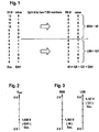
- Fig. 1 In the manner of a table, the 14-bit or 14-bit output signal of a sensor is displayed.
- the 0 to 13 bit digit bit area defining a binary number corresponds to 16384 distinguishable signal ranges.
- the sensor signal value is the decimal number Dec. 5241 is assumed, the associated binary value is specified under "value”. If this binary number is split into two 7-bit areas, the new binary values MSN and LSN given under the right-hand column "value" result.
- MSN stands for "most significant nibble”
- LSN stands for "least significant nibble”. Expressed in decimal numbers, MSN is 40 and LSN is 121.
- these subsections MSN and LSN are also referred to as short data words. In the lower right corner, a formula is used to show that both short data words add together again to the original decimal value Dec. 5241, provided that the decimal MSB value 40 is previously increased with the weighting factor 128 over the LSN value.
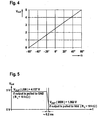
- the decimal value 5241 is mapped to the output voltage Vout going from 0V to 5V, with the full swing equal to the decimal value 16384.
- the decimal value 5241 results in a voltage value of 1,600 V.
- Fig. 4 schematically shows the analog output signal Vout for a sensor for recording angle values.
- the angles ⁇ passing through from -60 ° to + 60 ° are linearly assigned the voltage values from 0 V to 5 V.
- Fig. 5 shows in the timing diagram the successive transmission of Kurz briefly words LSN and MSN of Fig. 1 as different voltage levels Vout of 4.727 V and 1.563 V.
- a short transition of about 0.2 ms signals the change from LSN to MSN.
- the change is triggered in the embodiment in that it is detected in the sensor output, that the current flow direction has reversed on the transmission line, which is effected for example by switching the load resistance RL of VSS or GND to VDD.
- a sensor 1 is connected with its signal output 2 to a transmission path 3, which has a load resistance RL of, for example, 10 kOhm.
- the remote from the transmission line 3 end of the load resistor is connected to an I / O input of a receiver 4, such as a controller, which can selectively switch its output potential between VSS and VDD and thus in the sensor 1, the delivery of the respective short data word as an analog pseudo signal controls.
- a receiver 4 such as a controller
- FIG. 7 another realization of the external triggering of the short data words is shown schematically.
- the control is now via the supply voltage VDD, which is modulated by the controller 4 in a suitable manner via the I / O connection. Whether an overvoltage and undervoltage +/- ⁇ U is used or different overvoltages depends only on the detection circuit in the sensor.
- the load resistor RL is in this case connected to a fixed potential, eg VDD.
- Fig. 8 schematically shows a block diagram of the functional units of an embodiment for a sensor 1.
- the actual sensor element 6 delivers its analog measurement signal to an analog-to-digital converter 7.
- the subsequent processing is done digitally in the circuit block 8. If this parameter or program instructions needed, then these are from a Memory 9 fetched. There also intermediate results etc. can be stored.
- the result of the processing is the digital output signal of the block 8, a multi-digit data word, which is ultimately to be transmitted to a receiver, not shown.
- This data word is split in the circuit block 10 into two short data words MSN and LSN, which are buffered in the registers 11, 12.
- the content of the two registers is switched by a control device 14 at the correct time to a digital-to-analog converter 15 which converts the short data words MSN and LSN respectively into an analog pseudo signal, which is supplied via an amplifier 16 to an output terminal of the sensor 1 becomes.
- the required supply lines and control lines and clocks are not shown for the sake of clarity. Whether the individual functional units are realized wholly or partly by means of an adapted circuit or by means of a program is within the scope of the invention.
Landscapes
- Physics & Mathematics (AREA)
- General Physics & Mathematics (AREA)
- Arrangements For Transmission Of Measured Signals (AREA)
- Time-Division Multiplex Systems (AREA)
Claims (11)
- Procédé de transmission de données d'un capteur (1) vers un récepteur (4), caractérisé en ce que- chaque mot original de donnée dans un espace d'adressage mesuré est divisé en au moins deux mots de données brefs séparés (MSN, LSN) de sorte que le nombre d'adresses correspondantes est inférieur à celui du mot original de données,- les mots de données brefs séparés (MSN, LSN) sont convertis au moyen d'un convertisseur numérique-analogique (15) en un pseudo signal analogique,- un signal d'entrée est produit sur une entrée de signal du récepteur (4) par multiplexage temporel des pseudos signaux analogiques sur une sortie du capteur (1) et une liaison de transmission (3),- l'entrée de signal est couplée à un convertisseur analogique-numérique (5) qui convertit les pseudo-signaux analogiques en mots de données brefs (MSN, LSN) du côté du récepteur de sorte que le nombre des adresses correspond aux nombres des adresses des mots de données brefs (MSN, LSN) sur le capteur (1), et- les adresses correspondantes des mots de données brefs (MSN, LSN) sont réunies à nouveau à l'adresse correcte d'un mot de données du côté du récepteur qui correspond au mot original de données.
- Procédé selon la revendication 1, caractérisé en ce que la transmission des mots de données brefs (MSN, LSN) est réalisée au moyen d'un multiplexage modifié si les données du mot de données bref de poids fort (MSN) ne change pas entre deux mots de données successifs.
- Procédé selon la revendication 2, caractérisé en ce que lors du multiplexage modifié seuls les mots de données bref de poids faible (LSN) sont transmis.
- Procédé selon l'une quelconque des revendications 1 à 3, caractérisé en ce que la différence entre les mots de données brefs (MSN, LSN) corrects ou non est réalisée par des pauses de durées différentes.
- Procédé selon l'une quelconque des revendications 1 à 4, caractérisé en ce que les mots de données brefs (MSN, LSN) à différencier sont adaptés à la dynamique de la sortie du capteur.
- Procédé selon l'une quelconque des revendications 1 à 4, caractérisé en ce que les mots de données brefs (MSN, LSN) à différencier sont adaptés à des sens séparés du courant de sortie du capteur.
- Procédé selon la revendication 6, caractérisé en ce que les sens différents du courant sont produits au moyen d'une résistance de charge (RL) commutable sur la liaison de transmission (3) selon que l'extrémité distante de la liaison de transmission est commutée sur une haute ou une basse tension (VDD, VSS).
- Procédé selon la revendication 7, caractérisé en ce que la commutation de la résistance de charge (RL) est exécutée au moyen d'un port d'entrée-sortie du récepteur (I/O).
- Procédé selon l'une quelconque des revendications 1 à 4, caractérisé en ce que les mots de données brefs définis par un signal de commande du récepteur (4) sont adressables.
- Procédé selon la revendication 9, caractérisé en ce que le signal de commande du capteur (1) est produit sur une sortie séparée ou sur la connexion d'alimentation (VDD) .
- Capteur (1) avec une sortie de données pour la transmission de mots de données formées sur un signal du capteur vers un récepteur (4), caractérisé en ce que- le capteur (1) comporte des dispositifs (10, 11, 12) pour diviser chaque mot de données original à adressage mesuré en au moins deux mots de données brefs (MSN, LSN) avec un nombre d'adresses réduit par rapport à celui des adresses du mot de données original ;- il comporte un dispositif de multiplexage (13) qui est piloté par un dispositif de commande (14) et qui est connecté aux dispositifs (10, 11, 12) afin de séparer les pseudo signaux analogiques ;- il comporte un convertisseur numérique-analogique (15) sur le chemin de signal après le multiplexeur (13) afin de réunir les mots de données brefs séparés (MSN, LSN) en un pseudo signal analogique, et- un amplificateur (15) entre le multiplexeur (13) et la sortie du capteur (1) qui fournit la puissance nécessaire pour la transmission.
Applications Claiming Priority (2)
| Application Number | Priority Date | Filing Date | Title |
|---|---|---|---|
| DE102004007486 | 2004-02-12 | ||
| DE102004007486A DE102004007486A1 (de) | 2004-02-13 | 2004-02-13 | Sensor mit Multiplex-Datenausgang |
Publications (3)
| Publication Number | Publication Date |
|---|---|
| EP1575013A2 EP1575013A2 (fr) | 2005-09-14 |
| EP1575013A3 EP1575013A3 (fr) | 2007-10-31 |
| EP1575013B1 true EP1575013B1 (fr) | 2010-02-24 |
Family
ID=34813408
Family Applications (1)
| Application Number | Title | Priority Date | Filing Date |
|---|---|---|---|
| EP04030561A Active EP1575013B1 (fr) | 2004-02-13 | 2004-12-23 | Capteur avec une sortie pour sortir des données par multiplexage |
Country Status (5)
| Country | Link |
|---|---|
| US (1) | US7319418B2 (fr) |
| EP (1) | EP1575013B1 (fr) |
| JP (1) | JP4745679B2 (fr) |
| KR (1) | KR101089486B1 (fr) |
| DE (2) | DE102004007486A1 (fr) |
Cited By (1)
| Publication number | Priority date | Publication date | Assignee | Title |
|---|---|---|---|---|
| DE102012013072A1 (de) | 2012-07-02 | 2014-01-02 | Micronas Gmbh | Vorrichtung zur Auswertung eines Magnetfeldes |
Families Citing this family (27)
| Publication number | Priority date | Publication date | Assignee | Title |
|---|---|---|---|---|
| DE102007029660B4 (de) * | 2007-06-27 | 2011-06-01 | Vega Grieshaber Kg | Adaptiver Fehlerzähler für ein drahtloses Feldgerät |
| DE102007046560A1 (de) * | 2007-09-28 | 2009-04-02 | Siemens Ag | Feldgerät mit einem Analogausgang |
| EP2211147B1 (fr) * | 2009-01-23 | 2012-11-28 | Micronas GmbH | Procédé de contrôle du fonctionnement d'une circuit électrique |
| IT1397584B1 (it) * | 2009-12-18 | 2013-01-16 | Eltek Spa | Dispositivo di monitoraggio di una ruota di un veicolo e relativo metodo di comunicazione. |
| JP5737327B2 (ja) * | 2013-05-08 | 2015-06-17 | 株式会社デンソー | 通信システム、送信装置、受信装置 |
| EP2999943B1 (fr) | 2013-06-20 | 2022-04-06 | Allegro MicroSystems, LLC | Système et procédé de réalisation de codage de signal, représentatif d'une région de signature dans une cible, et représentatif d'un sens de rotation |
| US9787495B2 (en) | 2014-02-18 | 2017-10-10 | Allegro Microsystems, Llc | Signaling between master and slave components using a shared communication node of the master component |
| US9634715B2 (en) | 2014-02-18 | 2017-04-25 | Allegro Microsystems, Llc | Signaling between master and slave components using a shared communication node of the master component |
| US9851416B2 (en) | 2014-07-22 | 2017-12-26 | Allegro Microsystems, Llc | Systems and methods for magnetic field sensors with self-test |
| US9739846B2 (en) | 2014-10-03 | 2017-08-22 | Allegro Microsystems, Llc | Magnetic field sensors with self test |
| US10156461B2 (en) | 2014-10-31 | 2018-12-18 | Allegro Microsystems, Llc | Methods and apparatus for error detection in a magnetic field sensor |
| US10101410B2 (en) | 2015-10-21 | 2018-10-16 | Allegro Microsystems, Llc | Methods and apparatus for sensor having fault trip level setting |
| US10495700B2 (en) | 2016-01-29 | 2019-12-03 | Allegro Microsystems, Llc | Method and system for providing information about a target object in a formatted output signal |
| US10495485B2 (en) | 2016-05-17 | 2019-12-03 | Allegro Microsystems, Llc | Magnetic field sensors and output signal formats for a magnetic field sensor |
| DE102016119446A1 (de) * | 2016-10-12 | 2018-04-12 | Fujitsu Technology Solutions Intellectual Property Gmbh | Schnittstellenanordnung zum Anschluss eines Peripheriegeräts an eine Schnittstelle eines Host-Systems, Verfahren und elektronisches Gerät, insbesondere Computersystem |
| US10216559B2 (en) | 2016-11-14 | 2019-02-26 | Allegro Microsystems, Llc | Diagnostic fault communication |
| US10747708B2 (en) | 2018-03-08 | 2020-08-18 | Allegro Microsystems, Llc | Communication system between electronic devices |
| US10388362B1 (en) * | 2018-05-08 | 2019-08-20 | Micron Technology, Inc. | Half-width, double pumped data path |
| US10656170B2 (en) | 2018-05-17 | 2020-05-19 | Allegro Microsystems, Llc | Magnetic field sensors and output signal formats for a magnetic field sensor |
| US10725122B2 (en) | 2018-07-20 | 2020-07-28 | Allegro Microsystems, Llc | Ratiometric sensor output topology and methods |
| US11686597B2 (en) | 2019-06-07 | 2023-06-27 | Allegro Microsystems, Llc | Magnetic field sensors and output signal formats for magnetic field sensors |
| US11942831B2 (en) | 2020-01-15 | 2024-03-26 | Allegro Microsystems, Llc | Three-phase BLDC motor driver/controller having diagnostic signal processing |
| US11029370B1 (en) | 2020-05-22 | 2021-06-08 | Allegro Microsystems, Llc | Sensor output control methods and apparatus |
| US11811569B2 (en) | 2020-09-01 | 2023-11-07 | Allegro Microsystems, Llc | Sensor integrated circuits having a single edge nibble transmission (SENT) output |
| US11885645B2 (en) | 2021-06-17 | 2024-01-30 | Allegro Microsystems, Llc | Supply voltage configurable sensor |
| US11848682B2 (en) | 2022-01-11 | 2023-12-19 | Allegro Microsystems, Llc | Diagnostic circuits and methods for analog-to-digital converters |
| US12061937B2 (en) | 2022-06-22 | 2024-08-13 | Allegro Microsystems, Llc | Methods and apparatus for sensor data consistency |
Family Cites Families (21)
| Publication number | Priority date | Publication date | Assignee | Title |
|---|---|---|---|---|
| DE2330263A1 (de) * | 1973-06-14 | 1975-01-09 | Licentia Gmbh | Uebertragungs- und vermittlungsverfahren mit hilfe der amplitudenselektion |
| US4494183A (en) * | 1982-06-17 | 1985-01-15 | Honeywell Inc. | Process variable transmitter having a non-interacting operating range adjustment |
| US4592002A (en) * | 1983-12-13 | 1986-05-27 | Honeywell Inc. | Method of digital temperature compensation and a digital data handling system utilizing the same |
| US4591855A (en) * | 1983-12-27 | 1986-05-27 | Gte Communication Products Corporation | Apparatus for controlling a plurality of current sources |
| JPS63245599A (ja) * | 1987-03-31 | 1988-10-12 | 株式会社日立製作所 | 2線式通信装置用伝送方法 |
| DE3803872A1 (de) * | 1988-02-09 | 1989-08-17 | Messerschmitt Boelkow Blohm | Einrichtung zur inertialen geschwindigkeits- oder beschleunigungsmessung und schaltungsanordnung zur signalaufbereitung und -verarbeitung hierfuer |
| JPH0632151B2 (ja) * | 1988-09-07 | 1994-04-27 | セコム株式会社 | 検針システム |
| DE4035996A1 (de) | 1990-11-12 | 1992-05-14 | Siemens Ag | Verfahren zur simultanen uebertragung von daten auf einem uebertragungskanal |
| US5361218A (en) * | 1992-08-11 | 1994-11-01 | Itt Corporation | Self-calibrating sensor |
| US5481200A (en) * | 1993-09-15 | 1996-01-02 | Rosemont Inc. | Field transmitter built-in test equipment |
| JP3412349B2 (ja) * | 1994-12-28 | 2003-06-03 | 株式会社日立製作所 | 制御装置 |
| US5815100A (en) * | 1996-06-04 | 1998-09-29 | Hewlett-Packard Company | Voltage multiplexed chip I/O for multi-chip modules |
| KR100238674B1 (ko) | 1997-01-27 | 2000-01-15 | 윤종용 | 디지털 스틸 카메라의 영상데이터 중간처리 방법 |
| DE19815011A1 (de) | 1998-04-03 | 1999-10-14 | Temic Semiconductor Gmbh | Verfahren zur Übertragung von digitalen Sendesignalen |
| DE19819265C1 (de) * | 1998-04-30 | 1999-08-19 | Micronas Intermetall Gmbh | Verfahren zum Parametrieren einer integrierten Schaltungsanordnung und integrierte Schaltungsanordnung hierfür |
| US6744376B1 (en) * | 1998-08-26 | 2004-06-01 | The Johns Hopkins University | Remote input/output (RIO) smart sensor analog-digital chip |
| DE19930661A1 (de) * | 1999-07-02 | 2001-01-18 | Siemens Ag | Meßumformer |
| DE19946776A1 (de) | 1999-09-29 | 2001-04-12 | Bosch Gmbh Robert | Verfahren und Vorrichtung zu bidirektionalen Kommunikation wenigstens zweier Kommunikationsteilnehmer |
| DE10121879A1 (de) * | 2001-05-05 | 2002-11-07 | Conti Temic Microelectronic | Verfahren zur Übertragung eines Sensordatensignals und eines Zusatzdatensignals von einer Sensorbaugruppe zu wenigstens einem Empfänger |
| DE50208793D1 (de) * | 2001-06-27 | 2007-01-04 | Fraunhofer Ges Forschung | Verfahren und vorrichtung zum vorbereiten eines sensorsignals eines positionssensors für eine übertragung zu einer auswerteeinheit |
| JP2004145474A (ja) * | 2002-10-22 | 2004-05-20 | Yokohama Rubber Co Ltd:The | タイヤモニタリングシステム並びにそのモニタ受信機とモニタ装置及びセンサ装置 |
-
2004
- 2004-02-13 DE DE102004007486A patent/DE102004007486A1/de not_active Withdrawn
- 2004-12-23 DE DE502004010803T patent/DE502004010803D1/de active Active
- 2004-12-23 EP EP04030561A patent/EP1575013B1/fr active Active
-
2005
- 2005-02-14 KR KR1020050012029A patent/KR101089486B1/ko active IP Right Grant
- 2005-02-14 US US11/057,711 patent/US7319418B2/en active Active
- 2005-02-14 JP JP2005036013A patent/JP4745679B2/ja active Active
Cited By (3)
| Publication number | Priority date | Publication date | Assignee | Title |
|---|---|---|---|---|
| DE102012013072A1 (de) | 2012-07-02 | 2014-01-02 | Micronas Gmbh | Vorrichtung zur Auswertung eines Magnetfeldes |
| DE102012013072B4 (de) * | 2012-07-02 | 2015-01-08 | Micronas Gmbh | Vorrichtung zur Auswertung eines Magnetfeldes |
| US9291685B2 (en) | 2012-07-02 | 2016-03-22 | Micronas Gmbh | Device for evaluating a magnetic field |
Also Published As
| Publication number | Publication date |
|---|---|
| JP4745679B2 (ja) | 2011-08-10 |
| US7319418B2 (en) | 2008-01-15 |
| KR101089486B1 (ko) | 2011-12-02 |
| EP1575013A3 (fr) | 2007-10-31 |
| KR20060041930A (ko) | 2006-05-12 |
| DE102004007486A1 (de) | 2005-10-27 |
| JP2005228336A (ja) | 2005-08-25 |
| EP1575013A2 (fr) | 2005-09-14 |
| DE502004010803D1 (de) | 2010-04-08 |
| US20050243184A1 (en) | 2005-11-03 |
Similar Documents
| Publication | Publication Date | Title |
|---|---|---|
| EP1575013B1 (fr) | Capteur avec une sortie pour sortir des données par multiplexage | |
| DE2822672C2 (fr) | ||
| DE102008062865A1 (de) | Serial-Peripheral-Interface-Schnittstelle mit verminderter Verbindungsleitungsanzahl | |
| DE102007046560A1 (de) | Feldgerät mit einem Analogausgang | |
| DE102012201170A1 (de) | Vorrichtung zur Übertragung von Sensordaten | |
| WO2014166656A1 (fr) | Appareil d'alimentation d'un transducteur de mesure, système destiné à être utilisé dans les techniques d'automatisation, et procédé d'utilisation dudit système | |
| DE2333299C3 (de) | Schaltungsanordnung zur Umsetzung von Analog-Signalen in PCM-Signale und von PCM-Signalen in Analog-Signale | |
| WO2010046179A2 (fr) | Dispositif et procédé de transmission de données entre un appareil de mesure de position et une électronique d'aval | |
| DE102005043489B4 (de) | Automatisierungstechnische Einrichtung | |
| DE102005043478A1 (de) | Automatisierungstechnische Einrichtung | |
| DE102008057474A1 (de) | Meßumformer | |
| DE102005043482A1 (de) | Automatisierungstechnische Einrichtung | |
| DE3921962C2 (fr) | ||
| EP1203933B1 (fr) | Dispositif capteur pour la mesure d'au moins une grandeur | |
| DE3535118C2 (de) | Verfahren zur Analog-Digital-Wandlung von analogen Spannungen | |
| DE102007060555A1 (de) | Vorrichtung zur Übertragung von elektrischer Energie und Information | |
| EP3032429B1 (fr) | Procede et dispositif destines a la lecture d'un flux seriel de donnees | |
| DE102005043487A1 (de) | Automatisierungstechnische Einrichtung | |
| DE102005043485A1 (de) | Automatisierungstechnische Einrichtung | |
| DE102005043488A1 (de) | Automatisierungstechnische Einrichtung | |
| DE102008050612A1 (de) | Verfahren zum Testen des Verhaltens einer Prozessanlage | |
| EP2789210A1 (fr) | Procédé de commande d'une installation de signalisation à plusieurs couleurs et installation de signalisation à plusieurs couleurs | |
| DE3300218C2 (de) | Datenfernübertragungssystem | |
| DE102013216564A1 (de) | Verfahren zur Erkennung einer Doppeladressierung von Slaves in einem Master-Slave-Bussystem | |
| EP2850396B1 (fr) | Procede de transfert d'informations et dispositif pour réaliser le procédé |
Legal Events
| Date | Code | Title | Description |
|---|---|---|---|
| PUAI | Public reference made under article 153(3) epc to a published international application that has entered the european phase |
Free format text: ORIGINAL CODE: 0009012 |
|
| AK | Designated contracting states |
Kind code of ref document: A2 Designated state(s): AT BE BG CH CY CZ DE DK EE ES FI FR GB GR HU IE IS IT LI LT LU MC NL PL PT RO SE SI SK TR |
|
| AX | Request for extension of the european patent |
Extension state: AL BA HR LV MK YU |
|
| PUAL | Search report despatched |
Free format text: ORIGINAL CODE: 0009013 |
|
| AK | Designated contracting states |
Kind code of ref document: A3 Designated state(s): AT BE BG CH CY CZ DE DK EE ES FI FR GB GR HU IE IS IT LI LT LU MC NL PL PT RO SE SI SK TR |
|
| AX | Request for extension of the european patent |
Extension state: AL BA HR LV MK YU |
|
| 17P | Request for examination filed |
Effective date: 20080502 |
|
| AKX | Designation fees paid |
Designated state(s): DE FR GB IT NL |
|
| GRAP | Despatch of communication of intention to grant a patent |
Free format text: ORIGINAL CODE: EPIDOSNIGR1 |
|
| GRAS | Grant fee paid |
Free format text: ORIGINAL CODE: EPIDOSNIGR3 |
|
| GRAA | (expected) grant |
Free format text: ORIGINAL CODE: 0009210 |
|
| AK | Designated contracting states |
Kind code of ref document: B1 Designated state(s): DE FR GB IT NL |
|
| REG | Reference to a national code |
Ref country code: GB Ref legal event code: FG4D Free format text: NOT ENGLISH |
|
| REF | Corresponds to: |
Ref document number: 502004010803 Country of ref document: DE Date of ref document: 20100408 Kind code of ref document: P |
|
| REG | Reference to a national code |
Ref country code: NL Ref legal event code: T3 |
|
| PLBE | No opposition filed within time limit |
Free format text: ORIGINAL CODE: 0009261 |
|
| STAA | Information on the status of an ep patent application or granted ep patent |
Free format text: STATUS: NO OPPOSITION FILED WITHIN TIME LIMIT |
|
| 26N | No opposition filed |
Effective date: 20101125 |
|
| PG25 | Lapsed in a contracting state [announced via postgrant information from national office to epo] |
Ref country code: IT Free format text: LAPSE BECAUSE OF FAILURE TO SUBMIT A TRANSLATION OF THE DESCRIPTION OR TO PAY THE FEE WITHIN THE PRESCRIBED TIME-LIMIT Effective date: 20100224 |
|
| REG | Reference to a national code |
Ref country code: NL Ref legal event code: V1 Effective date: 20110701 |
|
| PG25 | Lapsed in a contracting state [announced via postgrant information from national office to epo] |
Ref country code: NL Free format text: LAPSE BECAUSE OF NON-PAYMENT OF DUE FEES Effective date: 20110701 |
|
| REG | Reference to a national code |
Ref country code: FR Ref legal event code: PLFP Year of fee payment: 12 |
|
| REG | Reference to a national code |
Ref country code: FR Ref legal event code: PLFP Year of fee payment: 13 |
|
| REG | Reference to a national code |
Ref country code: DE Ref legal event code: R082 Ref document number: 502004010803 Country of ref document: DE Representative=s name: KOCH-MUELLER PATENTANWALTSGESELLSCHAFT MBH, DE Ref country code: DE Ref legal event code: R081 Ref document number: 502004010803 Country of ref document: DE Owner name: TDK-MICRONAS GMBH, DE Free format text: FORMER OWNER: MICRONAS GMBH, 79108 FREIBURG, DE |
|
| REG | Reference to a national code |
Ref country code: FR Ref legal event code: PLFP Year of fee payment: 14 |
|
| REG | Reference to a national code |
Ref country code: FR Ref legal event code: CD Owner name: TDK-MICRONAS GMBH, DE Effective date: 20180717 |
|
| PGFP | Annual fee paid to national office [announced via postgrant information from national office to epo] |
Ref country code: GB Payment date: 20181218 Year of fee payment: 15 Ref country code: FR Payment date: 20181219 Year of fee payment: 15 |
|
| GBPC | Gb: european patent ceased through non-payment of renewal fee |
Effective date: 20191223 |
|
| PG25 | Lapsed in a contracting state [announced via postgrant information from national office to epo] |
Ref country code: FR Free format text: LAPSE BECAUSE OF NON-PAYMENT OF DUE FEES Effective date: 20191231 Ref country code: GB Free format text: LAPSE BECAUSE OF NON-PAYMENT OF DUE FEES Effective date: 20191223 |
|
| PGFP | Annual fee paid to national office [announced via postgrant information from national office to epo] |
Ref country code: DE Payment date: 20231214 Year of fee payment: 20 |