EP1574841A1 - Photoakustischer Gassensor - Google Patents

Photoakustischer Gassensor Download PDF

Info

Publication number
EP1574841A1
EP1574841A1 EP04005482A EP04005482A EP1574841A1 EP 1574841 A1 EP1574841 A1 EP 1574841A1 EP 04005482 A EP04005482 A EP 04005482A EP 04005482 A EP04005482 A EP 04005482A EP 1574841 A1 EP1574841 A1 EP 1574841A1
Authority
EP
European Patent Office
Prior art keywords
microphone
gas sensor
photoacoustic gas
sensor according
print
Prior art date
Legal status (The legal status is an assumption and is not a legal conclusion. Google has not performed a legal analysis and makes no representation as to the accuracy of the status listed.)
Withdrawn
Application number
EP04005482A
Other languages
English (en)
French (fr)
Inventor
Rolf Pleisch
Peter Steiner
Current Assignee (The listed assignees may be inaccurate. Google has not performed a legal analysis and makes no representation or warranty as to the accuracy of the list.)
Siemens AG
Original Assignee
Siemens Building Technologies AG
Siemens Schweiz AG
Priority date (The priority date is an assumption and is not a legal conclusion. Google has not performed a legal analysis and makes no representation as to the accuracy of the date listed.)
Filing date
Publication date
Application filed by Siemens Building Technologies AG, Siemens Schweiz AG filed Critical Siemens Building Technologies AG
Priority to EP04005482A priority Critical patent/EP1574841A1/de
Priority to PL05373064A priority patent/PL373064A1/xx
Priority to AU2005200839A priority patent/AU2005200839A1/en
Priority to KR1020050019244A priority patent/KR20060043530A/ko
Priority to CNB2005100545004A priority patent/CN100514031C/zh
Publication of EP1574841A1 publication Critical patent/EP1574841A1/de
Withdrawn legal-status Critical Current

Links

Images

Classifications

    • GPHYSICS
    • G01MEASURING; TESTING
    • G01NINVESTIGATING OR ANALYSING MATERIALS BY DETERMINING THEIR CHEMICAL OR PHYSICAL PROPERTIES
    • G01N21/00Investigating or analysing materials by the use of optical means, i.e. using sub-millimetre waves, infrared, visible or ultraviolet light
    • G01N21/17Systems in which incident light is modified in accordance with the properties of the material investigated
    • G01N21/1702Systems in which incident light is modified in accordance with the properties of the material investigated with opto-acoustic detection, e.g. for gases or analysing solids
    • G01N2021/1704Systems in which incident light is modified in accordance with the properties of the material investigated with opto-acoustic detection, e.g. for gases or analysing solids in gases

Definitions

  • the present invention relates to a photoacoustic gas sensor with a measuring and a Reference cell, a spotlight and a differential microphone for measuring the pressure difference between measuring and reference cell.
  • the difference microphone by a called Noise Canceling microphone is formed of the type used in mobile phones.
  • a first preferred embodiment of the gas sensor according to the invention is characterized characterized in that the differential microphone electrodes in the form of concentric Has circular rings.
  • the lower corner frequency of the difference microphone is less than 10Hz and is preferably between 1 and 4Hz.
  • a second preferred embodiment is characterized in that the differential microphone a can-shaped housing whose bottom the front of the microphone forms and whose back has a flange for fixing a back plate.
  • a third preferred embodiment is characterized in that the differential microphone is mounted on a print, which has a first annular groove for the positioning of having called curl.
  • the microphone electrodes in the form of concentric circular rings have the advantage that the Parts do not need to be aligned when populating the print, which is a simple Mounting with a robot allows.
  • the simple assembly is made by the first ring groove additionally relieved, because thereby the microphone with its case flange automatically is guided in the right position.
  • the photoacoustic gas sensor shown in Figure 1 consists of a measuring cell 1, a Reference cell 2, a arranged between the two cells 1 and 2 bidirectional Differential microphone 3, one of the measuring cell 1 associated micro light bulb 4 and a Reflector housing 5 with a reflector for focusing the emitted from the micro-lamp 4 Radiation on a in the micro light bulb 4 facing side wall of Measuring cell 1 arranged window into which an infrared bandpass filter 6 is inserted.
  • Measuring cell 1 and reference cell 2 are absolutely identical in terms of construction and dimensions. Both the measuring cell 1 and the reference cell 2 are on an outer side wall with a bore provided, in which a gas-permeable membrane 7 or 7 'used is.
  • the differential microphone 3 is mounted on a print 8 and on both sides of the Difference microphones 3 each have a seal 9 (optional) is provided.
  • the micro-bulb 4 is also mounted on a print, which is designated by the reference numeral 10.
  • the micro-bulb 4 emits light over a wide spectrum down to the infrared range; In most cases, a spectral line in the infrared range is used for gas detection.
  • the infrared bandpass filter 6 has a characteristic of the gas to be detected passband in the form of a narrow spectral band, which is for the detection of CO 2 at 4.25 microns, NH 3 at 10 microns and CH 4 at 3.4 microns.
  • the gas to be detected passes through the two gas-permeable membranes 7 and 7 'in the measuring cell 1 and in the reference cell 2.
  • the present in the measuring cell 1 gas is irradiated by modulated light of the micro-lamp 4.
  • the gas absorbs the light radiation and heats up. This results in a thermal expansion and, according to the modulation of the light radiation, a periodic pressure fluctuation, so that an acoustic pressure wave is caused whose strength is in direct proportion to the concentration of the gas.
  • the noise which strikes the membranes 7, 7 'from the outside, is attenuated by them the measuring cell 1 and the reference cell 2 each occur with identical strength.
  • This background noise thus compensates directly on the membrane of the microphone 3, without large signals arise, which would have to be subtracted electronically. Because on both sides of the microphone diaphragm the same pressure fluctuations prevail, finds a direct physical Subtraction of the signals caused by background noise, so that the microphone diaphragm not even distracted.
  • the microphone diaphragm thus provides directly by the Gas in the measuring cell 1 caused acoustic pressure and thus the concentration sought.
  • the microphone 3 is a so-called “noise canceling" microphone, as in mobile phones Application finds. If this microphone is used as a differential microphone and between two acoustically practically closed cells, namely between measuring cell 1 and reference cell 2, is installed, it shows very good, tailored to the task properties.
  • the microphone 3 is shown in section.
  • This consists of the representation a unilaterally open housing G of the shape of a box, the bottom of the front of the Microphones forms.
  • holes 11 for the sound passage to the between the bottom of the housing 10 and a metal baking electrode 12 clamped microphone membrane 13 provided of metallized plastic.
  • the side wall of the housing 18 is flanged at the back of the microphone and fixes a rear wall 14, with small Equalizing holes, so-called back ports 15 are provided and at their the metal baking electrode 12 facing inside a FET 16 and on its outside two circular electrodes 17 and 19 carries.
  • the back ports 15 are sufficiently large for low frequencies and make the frequency response of the microphone 3 to the lower corner frequency flat.
  • This lower corner frequency is due to the Capacity of the diaphragm 13 and the input resistance of the impedance converter used determined and is well below 10Hz, preferably between 1 and 4Hz, so that the Signal at the useful frequency of about 20 to 30Hz from the lower corner frequency only is negligibly affected.
  • the microphone 3 is mounted on the print 8, which has an annular groove 19 for the positioning of Crimping of the microphone 3, annular contact webs 20 and 21 for the two circular electrodes 17 and 18, and an annular groove 22 with some of the bottom of the annular groove through the Print 8 guided holes 23 has.
  • the holes 23 and the annular groove 22 allow the supply of air and sound from the outside to the back ports 15 without them on any holes must be aligned in the print 8.
  • the microphone 3 and the print 8 need not be aligned when loading, which allows easy assembly with a robot.
  • the assembly is still through the annular groove 19 facilitates the microphone 3 with its housing flange when placing automatically in the right position leads.
  • the circular electrodes 17 and 18 are connected to the circuit board 17 with Leitepoxy glued and electrically connected.
  • the outer contour of measuring cell 1, reference cell 2 and the reflector housing 5 is consistent throughout, so that the parts as Pull extruded profiles cost-effectively and keep the necessary processing to a minimum is reduced.
  • the production / provision of the individual components of the sensor i. of the reflector 5 with its housing, the two Cell body for measuring cell 1 and reference cell 2, the bandpass filter 6, the microphone 3 and the Mikroglühlampe 4.
  • the bandpass filter 6 is glued into the measuring cell 1 and then the Microphone 3 mounted on the print 8.
  • Measuring cell 1 and reference cell 2 are preferably made made of aluminum or die-cast zinc.
  • FIG. 4 which is done by the batch batch processing shown in FIG. It is in each case a reference cell 2 with the populated microphone print 8, the measuring cell 1, the the reflector 24 containing reflector housing 5, in which the micro-lamp 4 is inserted is connected to the populated microglamp print 10 in a stack, either by gluing or by clamping together.
  • the seals 9 (Fig. 1) is not required, because by the adhesive bond, the interior of the cell body 1 and 2 is sealed.
  • the clamping takes place by means of a longitudinal direction of the sensor (Direction of the arrows in Fig. 3) acting resilient member, such as a clip.
  • the membranes 7, 7 'used In the measuring cell 1 and the reference cell 2 of the finished measuring module M are subsequently the membranes 7, 7 'used and finally the measuring module M on a Modulprint P equipped, which can be done by gluing or soldering.
  • the pre-assembled measuring module M is complete and functional and can be tested in advance as a unit before it on the Modulprint P is populated.
  • the measuring module M can be used on any other circuit boards such as a component are inserted as a sub-module, wherein for the microphone 3, the reflector 24 and the Micro light bulb 4 no tolerance or alignment problems arise.

Landscapes

  • Physics & Mathematics (AREA)
  • Health & Medical Sciences (AREA)
  • Life Sciences & Earth Sciences (AREA)
  • Chemical & Material Sciences (AREA)
  • Analytical Chemistry (AREA)
  • Biochemistry (AREA)
  • General Health & Medical Sciences (AREA)
  • General Physics & Mathematics (AREA)
  • Immunology (AREA)
  • Pathology (AREA)
  • Investigating Or Analysing Materials By Optical Means (AREA)
  • Investigating Or Analyzing Materials By The Use Of Ultrasonic Waves (AREA)

Abstract

Ein photoakustischer Gassensor enthält eine Mess- und eine Referenzzelle (1 bzw. 2), einen Strahler und ein Differenzmikrofon (3) für die Messung der Druckdifferenz zwischen Mess- und Referenzzelle (1 bzw. 2). Das Differenzmikrofon (3) ist durch ein sogenanntes Noise Cancelling Mikrofon der in Mobiltelefonen verwendeten Art gebildet und weist Elektroden in der Form von konzentrischen Kreisringen sowie ein dosenförmiges Gehäuse auf, dessen Boden die Vorderseite des Mikrofons bildet und dessen Rückseite eine Bördelung für die Fixierung einer Rückplatte aufweist. Das Differenzmikrofon (3) ist auf einem Print (8) befestigt ist, welcher eine erste Ringnut für die Positionierung der genannten Bördelung aufweist. <IMAGE>

Description

Die vorliegende Erfindung betrifft einen photoakustischen Gassensor mit einer Mess- und einer Referenzzelle, einem Strahler und einem Differenzmikrofon für die Messung der Druckdifferenz zwischen Mess- und Referenzzelle.
Ein in der DE-A-40 18 393 beschriebener photoakustischer Gassensor dieser Art wird bisher kaum eingesetzt, weil praktisch keine günstigen Mikrofone verfügbar und übliche günstige Mikrofone für die typischen tiefen Signalfrequenzen nur sehr beschränkt geeignet sind. Aus diesem Grund werden zur Unterdrückung von Störschallquellen meistens zwei Mikrofone in elektrischer Differenzschaltung eingesetzt (siehe dazu EP-A-0 855 592). Dabei hat man aber das Problem, Mikrofone mit einer geeignet tiefen unteren Eckfrequenz zu finden, weil günstige Mikrofone aus Audioapplikationen eine typische untere 3dB-Frequenz bei 20 bis 30Hz, also im Bereich der Signalfrequenz des Gassensors, haben, was zu Streuungen der Eckfrequenz und Veränderungen von dieser durch Umwelteinflüsse führt. Ausserdem ist die Differenzbildung schwierig, weil die Mikrofone auf Messgenauigkeit im Prozentbereich gepaart werden müssen. Das führt zusammen mit der erwähnten Drift der 3dB-Frequenz dazu, dass eine wirksame Störunterdrückung kaum realisierbar ist.
Durch die Erfindung soll nun ein in der Praxis einsetzbarer photoakustischer Gassensor der eingangs genannten Art angegeben werden, dessen Differenzmikrofon kostengünstig und für die für photoakustische Gassensoren typischen tiefen Signalfrequenzen geeignet ist.
Diese Aufgabe wird erfindungsgemäss dadurch gelöst, dass das Differenzmikrofon durch ein so genanntes Noise Cancelling Mikrofon der in Mobiltelefonen verwendeten Art gebildet ist.
Da diese Mikrofone im Freifeld einen völlig unbrauchbaren Frequenzgang aufweisen, erscheinen sie als ungeeignet für die typische Signalfrequenz von 20 bis 30 Hz. Praktische Versuche haben aber das überraschende Ergebnis gezeigt, dass die Mikrofone für die vorgesehene Anwendung in photoakustischen Gassensoren sehr gute Eigenschaften mit einem flachen Frequenzgang bis zum 3dB-Punkt aufweisen. Die Eckfrequenz liegt in der Regel bei etwa 1 bis 4Hz, also deutlich unter 10Hz, so dass sie das Signal bei der Nutzfrequenz nur unwesentlich beeinflusst. Dazu kommt, dass die Mikrofone ausserordentlich kostengünstig und in unterschiedlichsten miniaturisierten Bauformen erhältlich sind.
Eine erste bevorzugte Ausführungsform des erfindungsgemässen Gassensors ist dadurch gekennzeichnet, dass das Differenzmikrofon Elektroden in der Form von konzentrischen Kreisringen aufweist. Die untere Eckfrequenz des Differenzmikrofons ist kleiner als 10Hz und liegt vorzugsweise zwischen 1 und 4Hz.
Eine zweite bevorzugte Ausführungsform ist dadurch gekennzeichnet, dass das Differenzmikrofon ein dosenförmiges Gehäuse aufweist, dessen Boden die Vorderseite des Mikrofons bildet und dessen Rückseite eine Bördelung für die Fixierung einer Rückplatte aufweist.
Eine dritte bevorzugte Ausführungsform ist dadurch gekennzeichnet, dass das Differenzmikrofon auf einem Print befestigt ist, welche eine erste Ringnut für die Positionierung der genannten Bördelung aufweist.
Die Mikrofonelektroden in der Form von konzentrischen Kreisringen haben den Vorteil, dass die Teile beim Bestücken des Prints nicht ausgerichtet zu werden brauchen, was eine einfache Montage mit einem Roboter ermöglicht. Die einfache Montage wird durch die erste Ringnut noch zusätzlich erleichtert, weil dadurch das Mikrofon mit seiner Gehäusebördelung automatisch in die richtige Position geführt wird.
Weitere bevorzugte Ausführungsformen und vorteilhafte Weiterentwicklungen des erfindungsgemässen photoakustischen Gassensors sind in den abhängigen Ansprüchen 5 bis 9 beansprucht.
Im Folgenden wird die Erfindung anhand eines Ausführungsbeispiels und der Zeichnungen näher erläutert; es zeigt:
  • Fig. 1 eine Explosionsdarstellung eines erfindungsgemässen photoakustischen Gassensors,
  • Fig. 2 ein Detail des Gassensors von Fig. 1;
  • Fig. 3 eine erste schematische Skizze zur Erläuterung der Herstellung des Gassensors; und
  • Fig. 4 eine zweite schematische Skizze zur Erläuterung der Herstellung des Gassensors.
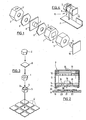
  • Der in Figur 1 dargestellte photoakustische Gassensor besteht aus einer Messzelle 1, einer Referenzzelle 2, einem zwischen den beiden Zellen 1 und 2 angeordneten bidirektionalen Differenzmikrofon 3, einer der Messzelle 1 zugeordneten Mikroglühlampe 4 und einem Reflektorgehäuse 5 mit einem Reflektor zur Bündelung der von der Mikroglühlampe 4 ausgesandten Strahlung auf ein in der der Mikroglühlampe 4 zugewandten Seitenwand der Messzelle 1 angeordnetes Fenster, in welches ein Infrarot-Bandpassfilter 6 eingesetzt ist. Messzelle 1 und Referenzzelle 2 sind bezüglich Aufbau und Dimensionen absolut identisch. Sowohl die Messzelle 1 als auch die Referenzzelle 2 sind an einer äusseren Seitenwand mit einer Bohrung versehen, in welche eine gaspermeable Membran 7 beziehungsweise 7' eingesetzt ist. Das Differenzmikrofon 3 ist auf einem Print 8 montiert und zu beiden Seiten des Differenzmikrofons 3 ist je eine Dichtung 9 (optional) vorgesehen. Die Mikroglühlampe 4 ist ebenfalls auf einem Print montiert, der mit dem Bezugszeichen 10 bezeichnet ist.
    Die Mikroglühlampe 4 emittiert Licht über ein breites Spektrum bis in den Infrarotbereich; in den meisten Fällen wird für die Gasdetektion eine Spektrallinie im Infrarotbereich verwendet. Das Infrarot-Bandpassfilter 6 hat einen für das zu detektierende Gas charakteristischen Durchlassbereich in Form eines schmalen Spektralbandes, welches für den Nachweis von CO2 bei 4.25 µm, von NH3 bei 10 µm und von CH4 bei 3.4 µm liegt. Das nachzuweisende Gas gelangt durch die beiden gaspermeablen Membranen 7 und 7' in die Messzelle 1 beziehungsweise in die Referenzzelle 2. Das in der Messzelle 1 anwesende Gas wird durch moduliertes Licht der Mikroglühlampe 4 bestrahlt. Das Gas absorbiert die Lichtstrahlung und erwärmt sich dadurch. Daraus entsteht eine thermische Ausdehnung und, entsprechend der Modulation der Lichtstrahlung, eine periodische Druckschwankung, so dass eine akustische Druckwelle verursacht wird, deren Stärke in direktem Verhältnis zur Konzentration des Gases steht.
    Der Störschall, der von aussen auf die Membranen 7, 7' trifft, wird durch diese abgeschwächt in der Messzelle 1 und der Referenzzelle 2 je mit identischer Stärke auftreten. Dieser Störschall kompensiert sich somit direkt an der Membran des Mikrofons 3, ohne dass grosse Signale entstehen, die elektronisch subtrahiert werden müssten. Da zu beiden Seiten der Mikrofonmembran die selben Druckschwankungen herrschen, findet an dieser eine direkte physikalische Subtraktion der durch Störschall verursachten Signale statt, so dass die Mikrofonmembran gar nicht erst ausgelenkt wird. Die Mikrofonmembran liefert somit unmittelbar den durch das Gas in der Messzelle 1 verursachten akustischen Druck und damit die gesuchte Konzentration.
    Das Mikrofon 3 ist ein so genanntes "Noise Cancelling" Mikrofon, wie es in Mobiltelefonen Anwendung findet. Wenn dieses Mikrofon als Differenzmikrofon verwendet und zwischen zwei akustisch praktisch geschlossenen Zellen, nämlich zwischen Messzelle 1 und Referenzzelle 2, eingebaut wird, zeigt es sehr gute, auf die Aufgabenstellung zugeschnittene Eigenschaften.
    In Fig. 2 ist das Mikrofon 3 im Schnitt dargestellt. Dieses besteht darstellungsgemäss aus einem einseitig offenen Gehäuse G von der Form einer Dose, deren Boden die Vorderseite des Mikrofons bildet. In diesem Boden sind Bohrungen 11 für den Schalldurchtritt zur der zwischen dem Boden des Gehäuses 10 und einer Metall-Backelektrode 12 eingespannten Mikrofonmembran 13 aus metallisiertem Kunststoff vorgesehen. Die Seitenwand des Gehäuses 18 ist an der Rückseite des Mikrofons umgebördelt und fixiert eine Rückwand 14, die mit kleinen Ausgleichsbohrungen, so genannten Back Ports 15 versehen ist und an ihrer der Metall-Backelektrode 12 zugewandten Innenseite einen FET 16 und an ihrer Aussenseite zwei Kreiselektroden 17 und 19 trägt.
    Die Back Ports 15 sind für tiefe Frequenzen genügend gross und machen den Frequenzgang des Mikrofons 3 bis zur unteren Eckfrequenz flach. Diese untere Eckfrequenz ist durch die Kapazität der Membran 13 und den Eingangswiderstand des verwendeten Impedanzwandlers bestimmt und liegt deutlich unter 10Hz liegt, vorzugsweise zwischen 1 und 4Hz, so dass das Signal bei der Nutzfrequenz von etwa 20 bis 30Hz von der unteren Eckfrequenz nur unwesentlich beeinflusst wird.
    Das Mikrofon 3 ist auf dem Print 8 befestigt, welcher eine Ringnut 19 für die Positionierung der Bördelung des Mikrofons 3, ringförmige Kontaktstege 20 und 21 für die beiden Kreiselektroden 17 beziehungsweise 18, sowie eine Ringnut 22 mit einigen vom Grund der Ringnut durch den Print 8 geführten Bohrungen 23 aufweist. Die Bohrungen 23 und die Ringnut 22 ermöglichen die Zufuhr von Luft und Schall von aussen zu den Back Ports 15, ohne dass diese auf irgendwelche Bohrungen im Print 8 ausgerichtet werden müssen.
    Das Mikrofon 3 und der Print 8 brauchen beim Bestücken nicht ausgerichtet zu werden, was eine leichte Montage mit einem Roboter ermöglicht. Die Montage wird noch durch die Ringnut 19 erleichtert, die das Mikrofon 3 mit seiner Gehäusebördelung beim Platzieren automatisch in die richtige Position führt. Die Kreiselektroden 17 und 18 werden mit der Leiterplatte 17 mit Leitepoxy verklebt und elektrisch verbunden. Die Aussenkontur von Messzelle 1, Referenzzelle 2 und des Reflektorgehäuse 5 ist durchgehend gleichbleibend, so dass sich die Teile als Strangprofile kostengünstig ziehen lassen und die notwendige Bearbeitung auf ein Minimum reduziert wird.
    Im Rahmen des Herstellungsprozess des Gassensors erfolgt die Fertigung/Bereitstellung der einzelnen Komponenten des Sensors, d.h. des Reflektors 5 mit seinem Gehäuse, der beiden Zellkörper für Messzelle 1 und Referenzzelle 2, des Bandpassfilters 6, des Mikrofons 3 und der Mikroglühlampe 4. Das Bandpassfilter 6 wird in die Messzelle 1 eingeklebt und dann wird das Mikrofon 3 auf dem Print 8 montiert. Messzelle 1 und Referenzzelle 2 bestehen vorzugsweise aus Aluminium oder Zinkdruckguss.
    Anschliessend werden diese Komponenten zu einem aus Fig. 4 ersichtlichen Messmodul M zusammen gesetzt, was durch die in Fig. 3 dargestellte Batch-Stapelverarbeitung erfolgt. Es wird jeweils eine Referenzzelle 2 mit dem bestückten Mikrofon-Print 8, der Messzelle 1, dem den Reflektor 24 enthaltenden Reflektorgehäuse 5, in welches die Mikroglühlampe 4 eingesetzt ist, und dem bestückten Mikroglühlampen-Print 10 zu einem Stapel verbunden, was entweder durch Kleben oder durch Zusammenspannen erfolgt. Im ersten Fall sind die Dichtungen 9 (Fig. 1) nicht erforderlich, weil durch die Klebeverbindung das Innere der Zellkörper 1 und 2 abgedichtet wird. Das Zusammenspannen erfolgt mit Hilfe eines in Längsrichtung des Sensors (Richtung der Pfeile in Fig. 3) wirkenden federnden Organs, beispielsweise einer Klammer.
    In die Messzelle 1 und die Referenzzelle 2 des fertigen Messmoduls M werden anschliessend die Membranen 7, 7' eingesetzt und schliesslich wird das Messmodul M auf einen Modulprint P bestückt, was durch Kleben oder Löten erfolgen kann. Das vormontierte Messmodul M ist komplett und funktionsfähig und kann vorab als Einheit geprüft werden, bevor es auf dem Modulprint P bestückt wird. Das Messmodul M kann auf beliebigen anderen Leiterplatten wie ein Bauteil als Sub-Modul eingefügt werden, wobei für das Mikrofon 3, den Reflektor 24 und die Mikroglühlampe 4 keine Toleranz- oder Ausrichtprobleme entstehen.
    Es ist offensichtlich, dass die beschriebene Herstellung des Sensors wesentlich einfacher und kostengünstiger ist als die bisher bekannten Herstellverfahren, bei denen das Mikrofon und die Mikroglühlampe auf einer Basisleiterplatte montiert und anschliessend die Messzelle um diese Komponenten herum einzeln aufgebaut wird.

    Claims (9)

    1. Photoakustischer Gassensor mit einer Mess- und einer Referenzzelle (1 bzw. 2), einem Strahler und einem Differenzmikrofon (3) für die Messung der Druckdifferenz zwischen Mess- und Referenzzelle (1 bzw. 2), dadurch gekennzeichnet, dass das Differenzmikrofon (3) durch ein so genanntes Noise Cancelling Mikrofon der in Mobiltelefonen verwendeten Art gebildet ist.
    2. Photoakustischer Gassensor nach Anspruch 1, dadurch gekennzeichnet, dass die untere Eckfrequenz des Differenzmikrofons (3) kleiner ist als 10Hz und vorzugsweise zwischen 1 und 4Hz liegt.
    3. Photoakustischer Gassensor nach Anspruch 2, dadurch gekennzeichnet, dass das Differenzmikrofon (3) Elektroden in der Form von konzentrischen Kreisringen (17, 18) aufweist.
    4. Photoakustischer Gassensor nach Anspruch 3, dadurch gekennzeichnet, dass das Differenzmikrofon (3) ein dosenförmiges Gehäuse (G) aufweist, dessen Boden die Vorderseite des Mikrofons bildet und dessen Rückseite eine Bördelung für die Fixierung einer Rückplatte (14) aufweist.
    5. Photoakustischer Gassensor nach Anspruch 4, dadurch gekennzeichnet, dass das Differenzmikrofon (3) auf einem Print (8) befestigt ist, welcher eine erste Ringnut (19) für die Positionierung der genannten Bördelung aufweist.
    6. Photoakustischer Gassensor nach Anspruch 5, dadurch gekennzeichnet, dass in der Rückplatte (14) Ausgleichsbohrungen (15) vorgesehen sind, und dass der Print (8) eine zweite Ringnut (22) mit durch den Print (8) geführten Bohrungen (23) aufweist, wobei durch die zweite Ringnut (22) und die genannten Bohrungen (23) der Zutritt von Schall aus dem Aussenraum zu den Ausgleichsbohrungen (15) ermöglicht ist.
    7. Photoakustischer Gassensor nach einem der Ansprüche 1 bis 6, dadurch gekennzeichnet, dass der Strahler durch eine auf einem Print (10) befestigte Mikroglühlampe (4) und einen in einem Reflektorgehäuse (5) vorgesehenen Reflektor (24) gebildet ist
    8. Photoakustischer Gassensor nach Anspruch 7, dadurch gekennzeichnet, dass die Messzelle (1), die Referenzzelle (2) und das Reflektorgehäuse (5) gleiche Aussenkonturen aufweisen.
    9. Photoakustischer Gassensor nach einem der Ansprüche 1 bis 8, dadurch gekennzeichnet, dass zu beiden Seiten des Differenzmikrofons (3) je ein Dichtungsplättchen (9) vorgesehen ist.
    EP04005482A 2004-03-08 2004-03-08 Photoakustischer Gassensor Withdrawn EP1574841A1 (de)

    Priority Applications (5)

    Application Number Priority Date Filing Date Title
    EP04005482A EP1574841A1 (de) 2004-03-08 2004-03-08 Photoakustischer Gassensor
    PL05373064A PL373064A1 (en) 2004-03-08 2005-02-22 Photoacoustic gas sensor
    AU2005200839A AU2005200839A1 (en) 2004-03-08 2005-02-24 Photoacoustic gas sensor
    KR1020050019244A KR20060043530A (ko) 2004-03-08 2005-03-08 광음향 가스 센서
    CNB2005100545004A CN100514031C (zh) 2004-03-08 2005-03-08 光声气敏元件

    Applications Claiming Priority (1)

    Application Number Priority Date Filing Date Title
    EP04005482A EP1574841A1 (de) 2004-03-08 2004-03-08 Photoakustischer Gassensor

    Publications (1)

    Publication Number Publication Date
    EP1574841A1 true EP1574841A1 (de) 2005-09-14

    Family

    ID=34814267

    Family Applications (1)

    Application Number Title Priority Date Filing Date
    EP04005482A Withdrawn EP1574841A1 (de) 2004-03-08 2004-03-08 Photoakustischer Gassensor

    Country Status (5)

    Country Link
    EP (1) EP1574841A1 (de)
    KR (1) KR20060043530A (de)
    CN (1) CN100514031C (de)
    AU (1) AU2005200839A1 (de)
    PL (1) PL373064A1 (de)

    Cited By (3)

    * Cited by examiner, † Cited by third party
    Publication number Priority date Publication date Assignee Title
    EP2604998A1 (de) * 2011-12-12 2013-06-19 ABB Research Ltd. Vorrichtung zur Gasanalyse
    US8848191B2 (en) 2012-03-14 2014-09-30 Honeywell International Inc. Photoacoustic sensor with mirror
    EP3550286A1 (de) * 2019-04-17 2019-10-09 Sensirion AG Photo-akustische gassensorvorrichtung

    Families Citing this family (2)

    * Cited by examiner, † Cited by third party
    Publication number Priority date Publication date Assignee Title
    KR20160061492A (ko) 2014-11-21 2016-06-01 삼성디스플레이 주식회사 휴대용 먼지 센서 및 이를 이용한 휴대전화
    CN110596236A (zh) * 2019-09-27 2019-12-20 湖北晟正汽车零部件有限公司 一种优化的尿素溶液浓度检测装置

    Citations (8)

    * Cited by examiner, † Cited by third party
    Publication number Priority date Publication date Assignee Title
    US4019056A (en) * 1975-04-28 1977-04-19 Diax Corporation Infrared laser detector employing a pressure controlled differential optoacoustic detector
    US4067653A (en) * 1976-08-27 1978-01-10 Nasa Differential optoacoustic absorption detector
    US4456796A (en) * 1981-03-25 1984-06-26 Hosiden Electronics Co., Ltd. Unidirectional electret microphone
    US4887300A (en) * 1986-07-17 1989-12-12 Aktieselskabet Bruel & Kjaer Pressure gradient microphone
    DE4018393A1 (de) * 1989-06-13 1990-12-20 Oehler Oscar Verfahren und vorrichtung zum messen von photosynthese-austauschgasen
    EP0742678A2 (de) * 1995-05-11 1996-11-13 AT&T Corp. Gradientmikrophon mit Rauschunterdrückungsanordnung
    WO1999030122A1 (en) * 1997-11-26 1999-06-17 Presens As Dynamic pressure sensor, photo acoustic gas detector, microphone, hydrophone and their manufacturing
    US6647118B1 (en) * 1999-07-27 2003-11-11 Nec Infrontia Corporation Noise canceling microphone unit for composing noise canceling handset by using normal housing

    Patent Citations (8)

    * Cited by examiner, † Cited by third party
    Publication number Priority date Publication date Assignee Title
    US4019056A (en) * 1975-04-28 1977-04-19 Diax Corporation Infrared laser detector employing a pressure controlled differential optoacoustic detector
    US4067653A (en) * 1976-08-27 1978-01-10 Nasa Differential optoacoustic absorption detector
    US4456796A (en) * 1981-03-25 1984-06-26 Hosiden Electronics Co., Ltd. Unidirectional electret microphone
    US4887300A (en) * 1986-07-17 1989-12-12 Aktieselskabet Bruel & Kjaer Pressure gradient microphone
    DE4018393A1 (de) * 1989-06-13 1990-12-20 Oehler Oscar Verfahren und vorrichtung zum messen von photosynthese-austauschgasen
    EP0742678A2 (de) * 1995-05-11 1996-11-13 AT&T Corp. Gradientmikrophon mit Rauschunterdrückungsanordnung
    WO1999030122A1 (en) * 1997-11-26 1999-06-17 Presens As Dynamic pressure sensor, photo acoustic gas detector, microphone, hydrophone and their manufacturing
    US6647118B1 (en) * 1999-07-27 2003-11-11 Nec Infrontia Corporation Noise canceling microphone unit for composing noise canceling handset by using normal housing

    Cited By (5)

    * Cited by examiner, † Cited by third party
    Publication number Priority date Publication date Assignee Title
    EP2604998A1 (de) * 2011-12-12 2013-06-19 ABB Research Ltd. Vorrichtung zur Gasanalyse
    US8848191B2 (en) 2012-03-14 2014-09-30 Honeywell International Inc. Photoacoustic sensor with mirror
    EP3550286A1 (de) * 2019-04-17 2019-10-09 Sensirion AG Photo-akustische gassensorvorrichtung
    WO2020212481A1 (en) * 2019-04-17 2020-10-22 Sensirion Ag Photoacoustic gas sensor device
    US11754492B2 (en) 2019-04-17 2023-09-12 Sensirion Ag Photoacoustic gas sensor device

    Also Published As

    Publication number Publication date
    KR20060043530A (ko) 2006-05-15
    CN100514031C (zh) 2009-07-15
    CN1667396A (zh) 2005-09-14
    AU2005200839A1 (en) 2005-09-22
    PL373064A1 (en) 2005-09-19

    Similar Documents

    Publication Publication Date Title
    DE69333058T2 (de) Piezoelektrischer Wandler
    EP1897365B1 (de) Kameraanordnung mit bildsensorabdichtung gegen umwelteinflüsse
    DE102014203881A1 (de) Bauteil mit Mikrofon- und Mediensensorfunktion
    EP0129714A2 (de) Elektrischer Kondensator
    DE2021656B2 (de) Elektrostatischer Lautsprecher
    EP0779170B1 (de) Schadstoffsonde
    DE102015107560A1 (de) Schallwandleranordnung mit MEMS-Schallwandler
    DE2906497C2 (de)
    WO2007098893A1 (de) Verfahren zum herstellen einer fluiddruckmesseinheit und komponente zum einsatz in einer fluiddruckmesseinheit
    DE102014113355B4 (de) Lautsprecherabdeckung
    DE3139917C2 (de)
    EP2281183B1 (de) Luftdrucksensor zur aufprallerkennung
    DE102020135152A1 (de) Unsichtbare mikrofonbaugruppe für ein fahrzeug
    EP1574841A1 (de) Photoakustischer Gassensor
    EP1574840A1 (de) Photoakustischer Gassensor und Verfahren zu dessen Herstellung
    EP1762117B1 (de) Kondensatormikrofon
    DE112005000037T5 (de) Piezoelektrischer elektroakustischer Wandler
    EP1582857A1 (de) Photoakustischer Gassensor mit einer Strahleranordnung mit einem Reflektor, und Verfahren zur Optimierung der Kontur des Reflektors
    DE102005053014B4 (de) Drucksensorgehäuse und Verfahren zu seiner Herstellung
    DE102015207788A1 (de) Mikromechanische Sensorvorrichtung
    DE10010514A1 (de) Optoelektronisches Mikrospektrometer
    EP2125407B1 (de) Doppeldichtlippe für türmodul einer fahrzeugtür
    WO2003087752A1 (de) Drucksensor
    DE102021210581A1 (de) Zugangselement für Medien an einem Sensor sowie Sensor mit einem derartigen Zugangselement
    DE4411853C2 (de) Optoakustischer Gassensor zur gleichzeitigen Detektion von mehreren Komponenten eines Gasgemisches

    Legal Events

    Date Code Title Description
    PUAI Public reference made under article 153(3) epc to a published international application that has entered the european phase

    Free format text: ORIGINAL CODE: 0009012

    AK Designated contracting states

    Kind code of ref document: A1

    Designated state(s): AT BE BG CH CY CZ DE DK EE ES FI FR GB GR HU IE IT LI LU MC NL PL PT RO SE SI SK TR

    AX Request for extension of the european patent

    Extension state: AL LT LV MK

    RAP1 Party data changed (applicant data changed or rights of an application transferred)

    Owner name: SIEMENS SCHWEIZ AG

    17P Request for examination filed

    Effective date: 20051010

    AKX Designation fees paid

    Designated state(s): AT BE BG CH CY CZ DE DK EE ES FI FR GB GR HU IE IT LI LU MC NL PL PT RO SE SI SK TR

    RAP1 Party data changed (applicant data changed or rights of an application transferred)

    Owner name: SIEMENS AKTIENGESELLSCHAFT

    STAA Information on the status of an ep patent application or granted ep patent

    Free format text: STATUS: THE APPLICATION IS DEEMED TO BE WITHDRAWN

    18D Application deemed to be withdrawn

    Effective date: 20100112