EP1574480A1 - Verfahren und Vorrichtung zur Aktivierung von Wasser mit Permanentmagneten - Google Patents
Verfahren und Vorrichtung zur Aktivierung von Wasser mit Permanentmagneten Download PDFInfo
- Publication number
- EP1574480A1 EP1574480A1 EP04005572A EP04005572A EP1574480A1 EP 1574480 A1 EP1574480 A1 EP 1574480A1 EP 04005572 A EP04005572 A EP 04005572A EP 04005572 A EP04005572 A EP 04005572A EP 1574480 A1 EP1574480 A1 EP 1574480A1
- Authority
- EP
- European Patent Office
- Prior art keywords
- water
- pole
- magnetic
- flow tube
- yokes
- Prior art date
- Legal status (The legal status is an assumption and is not a legal conclusion. Google has not performed a legal analysis and makes no representation as to the accuracy of the status listed.)
- Withdrawn
Links
- XLYOFNOQVPJJNP-UHFFFAOYSA-N water Substances O XLYOFNOQVPJJNP-UHFFFAOYSA-N 0.000 title claims abstract description 152
- 230000003213 activating effect Effects 0.000 title claims abstract description 47
- 238000000034 method Methods 0.000 title claims description 22
- 230000005291 magnetic effect Effects 0.000 claims abstract description 83
- 239000002184 metal Substances 0.000 claims abstract description 69
- 229910052751 metal Inorganic materials 0.000 claims abstract description 69
- 239000000919 ceramic Substances 0.000 claims abstract description 7
- 238000000465 moulding Methods 0.000 claims abstract description 6
- 239000002131 composite material Substances 0.000 claims description 16
- 150000002739 metals Chemical class 0.000 claims description 16
- 238000007747 plating Methods 0.000 claims description 14
- RYGMFSIKBFXOCR-UHFFFAOYSA-N Copper Chemical compound [Cu] RYGMFSIKBFXOCR-UHFFFAOYSA-N 0.000 claims description 9
- 229910052802 copper Inorganic materials 0.000 claims description 9
- 239000010949 copper Substances 0.000 claims description 9
- VYZAMTAEIAYCRO-UHFFFAOYSA-N Chromium Chemical compound [Cr] VYZAMTAEIAYCRO-UHFFFAOYSA-N 0.000 claims description 6
- BQCADISMDOOEFD-UHFFFAOYSA-N Silver Chemical compound [Ag] BQCADISMDOOEFD-UHFFFAOYSA-N 0.000 claims description 5
- PCHJSUWPFVWCPO-UHFFFAOYSA-N gold Chemical compound [Au] PCHJSUWPFVWCPO-UHFFFAOYSA-N 0.000 claims description 5
- 229910052737 gold Inorganic materials 0.000 claims description 5
- 239000010931 gold Substances 0.000 claims description 5
- 238000010030 laminating Methods 0.000 claims description 5
- 229910052709 silver Inorganic materials 0.000 claims description 5
- 239000004332 silver Substances 0.000 claims description 5
- 230000005292 diamagnetic effect Effects 0.000 claims description 3
- 230000004913 activation Effects 0.000 abstract description 22
- QVGXLLKOCUKJST-UHFFFAOYSA-N atomic oxygen Chemical compound [O] QVGXLLKOCUKJST-UHFFFAOYSA-N 0.000 description 4
- 230000004907 flux Effects 0.000 description 4
- 230000033116 oxidation-reduction process Effects 0.000 description 4
- 229910052760 oxygen Inorganic materials 0.000 description 4
- 239000001301 oxygen Substances 0.000 description 4
- 239000008399 tap water Substances 0.000 description 4
- 235000020679 tap water Nutrition 0.000 description 4
- 239000001257 hydrogen Substances 0.000 description 3
- 229910052739 hydrogen Inorganic materials 0.000 description 3
- 229920000915 polyvinyl chloride Polymers 0.000 description 3
- 239000004800 polyvinyl chloride Substances 0.000 description 3
- 241000894006 Bacteria Species 0.000 description 2
- XEEYBQQBJWHFJM-UHFFFAOYSA-N Iron Chemical compound [Fe] XEEYBQQBJWHFJM-UHFFFAOYSA-N 0.000 description 2
- 125000004435 hydrogen atom Chemical group [H]* 0.000 description 2
- TUJKJAMUKRIRHC-UHFFFAOYSA-N hydroxyl Chemical compound [OH] TUJKJAMUKRIRHC-UHFFFAOYSA-N 0.000 description 2
- 229910001172 neodymium magnet Inorganic materials 0.000 description 2
- 230000036647 reaction Effects 0.000 description 2
- 239000013535 sea water Substances 0.000 description 2
- 241000251468 Actinopterygii Species 0.000 description 1
- OKTJSMMVPCPJKN-UHFFFAOYSA-N Carbon Chemical compound [C] OKTJSMMVPCPJKN-UHFFFAOYSA-N 0.000 description 1
- UFHFLCQGNIYNRP-UHFFFAOYSA-N Hydrogen Chemical compound [H][H] UFHFLCQGNIYNRP-UHFFFAOYSA-N 0.000 description 1
- BGPVFRJUHWVFKM-UHFFFAOYSA-N N1=C2C=CC=CC2=[N+]([O-])C1(CC1)CCC21N=C1C=CC=CC1=[N+]2[O-] Chemical compound N1=C2C=CC=CC2=[N+]([O-])C1(CC1)CCC21N=C1C=CC=CC1=[N+]2[O-] BGPVFRJUHWVFKM-UHFFFAOYSA-N 0.000 description 1
- QJVKUMXDEUEQLH-UHFFFAOYSA-N [B].[Fe].[Nd] Chemical compound [B].[Fe].[Nd] QJVKUMXDEUEQLH-UHFFFAOYSA-N 0.000 description 1
- 230000003113 alkalizing effect Effects 0.000 description 1
- 125000000129 anionic group Chemical group 0.000 description 1
- 230000000903 blocking effect Effects 0.000 description 1
- 229910052799 carbon Inorganic materials 0.000 description 1
- 238000001914 filtration Methods 0.000 description 1
- 239000003574 free electron Substances 0.000 description 1
- 239000010797 grey water Substances 0.000 description 1
- 239000008214 highly purified water Substances 0.000 description 1
- 230000006698 induction Effects 0.000 description 1
- 150000002500 ions Chemical class 0.000 description 1
- 229910052742 iron Inorganic materials 0.000 description 1
- 239000000463 material Substances 0.000 description 1
- 230000000737 periodic effect Effects 0.000 description 1
- 229920005749 polyurethane resin Polymers 0.000 description 1
- 230000001737 promoting effect Effects 0.000 description 1
Images

Classifications
-
- C—CHEMISTRY; METALLURGY
- C02—TREATMENT OF WATER, WASTE WATER, SEWAGE, OR SLUDGE
- C02F—TREATMENT OF WATER, WASTE WATER, SEWAGE, OR SLUDGE
- C02F1/00—Treatment of water, waste water, or sewage
- C02F1/48—Treatment of water, waste water, or sewage with magnetic or electric fields
- C02F1/481—Treatment of water, waste water, or sewage with magnetic or electric fields using permanent magnets
-
- C—CHEMISTRY; METALLURGY
- C02—TREATMENT OF WATER, WASTE WATER, SEWAGE, OR SLUDGE
- C02F—TREATMENT OF WATER, WASTE WATER, SEWAGE, OR SLUDGE
- C02F1/00—Treatment of water, waste water, or sewage
- C02F1/005—Systems or processes based on supernatural or anthroposophic principles, cosmic or terrestrial radiation, geomancy or rhabdomancy
-
- C—CHEMISTRY; METALLURGY
- C02—TREATMENT OF WATER, WASTE WATER, SEWAGE, OR SLUDGE
- C02F—TREATMENT OF WATER, WASTE WATER, SEWAGE, OR SLUDGE
- C02F1/00—Treatment of water, waste water, or sewage
- C02F1/46—Treatment of water, waste water, or sewage by electrochemical methods
- C02F1/4606—Treatment of water, waste water, or sewage by electrochemical methods for producing oligodynamic substances to disinfect the water
-
- C—CHEMISTRY; METALLURGY
- C02—TREATMENT OF WATER, WASTE WATER, SEWAGE, OR SLUDGE
- C02F—TREATMENT OF WATER, WASTE WATER, SEWAGE, OR SLUDGE
- C02F1/00—Treatment of water, waste water, or sewage
- C02F1/46—Treatment of water, waste water, or sewage by electrochemical methods
- C02F1/469—Treatment of water, waste water, or sewage by electrochemical methods by electrochemical separation, e.g. by electro-osmosis, electrodialysis, electrophoresis
Definitions
- the present invention relates to methods and apparatuses for activating water and, particularly, to a method of activating water over a wide range from supplied clean water and gray water to drain water and an apparatus for activating such water.
- a scheme of activating water by splitting molecular population of water with the use of a magnetic force to reduce the size of a cluster (molecular assembly) of water has been well known.
- a system for activation in which water reserved in a reservoir is processed by a filtration unit and a magnetic processing unit (refer to Japanese Patent Laid-Open Publication No. 2002-254082, pp. 2-6, FIG. 1), an apparatus for activating a flow of water in which a permanent magnet is attached to the outside of a water flow tube and an image magnet is formed symmetrically to the surface of the water flow tube (refer to Japanese Patent Laid-Open PublicationNo. 2002-192159, pp. 2-3, FIG.
- activation is performed by allowing water to pass between the S pole and the N pole of at least a pair of magnets.
- the inventor of the present invention has previously suggested a water activating method in which the S pole and the N pole are opposed to each other and, for the purpose of efficient activation, a non-magnetic conductive metal plate is used to cause an electromotive current occurring in a direction perpendicular to a flow of water to repulsively act, thereby acting electrons and also a magnetic force upon the flow of water, and an apparatus for this method (refer to Japanese Patent Laid-Open Publication No. 11-138173, pp. 2-5, FIG. 1).
- This apparatus has a structural problem, however, that a carbon electrode has to be fitted into the water flow tube, thereby disadvantageously causing an inconvenience of adherence for the purpose of preventing water leakage.
- the conventional water activating apparatuses have the problem that there is no way to improve the efficiency of water activation other than intensifying the magnetic force.
- the inventor has previously suggested the above-described method and apparatus, which, however, have the problem in view of the structure for preventing water leakage.
- an object of the present invention is to achieve a water activating apparatus which solves the above-described problems, the water activating apparatus having a relatively simple structure without the possibility of water leakage and achieving highly efficient activation, and is also to achieve an activating method used for the water activating apparatus.
- a water activating method is characterized in that at least one pair of permanent magnets with an N pole and an S pole thereof being opposed to each other is provided across a water flow tube, concave yokes in a pair that are formed by molding magnetic metal or magnetic ceramic are arranged so as to be opposed to each other with a predetermined gap therebetween and each to magnetically make a contact with a surface of one of the permanent magnets opposite to a surface thereof that is opposed to another one of the permanent magnets, a non-magnetic conductive metal layer is laminated inside the concave yokes including the gap therebetween and excluding contact areas that make a contact with the permanent magnets, the non-magnetic conductive metal layer being formed by single plating made of either one of metals of copper, silver, and gold or composite plating made of the metals, or a composite metal plate formed by laminating films made of the metals, thereby improving an electric potential inside the pair of the concave yokes, with
- an apparatus is characterized by including at least one pair of concave yokes formed by molding magnetic metal or magnetic ceramic; an N pole formed by a permanent magnet provided so as to magnetically make a contact with an inner surface of one of the concave yokes; and an S pole formed by a permanent magnet provided so as to magnetically make a contact with an inner surface of another one of the concave yokes, the concave yokes being arranged so as to have a predetermined gap with the N pole and the S pole being opposed to each other, a non-magnetic conductive metal layer being laminated inside the concave yokes including the gap therebetween and excluding contact areas that make a contact with the permanent magnets, the non-magnetic conductive metal layer being formed by single plating made of either one of metals of copper, silver, and gold or composite plating made of the metals, or a composite metal plate formed by laminating films made of the metals, and a non-magnetic water flow tube being
- the present activating apparatus is characterized in that a box is provided for accommodating the concave yokes including a part of the water flow tube, and an outer surface of the box is covered with either one of chrome plating and a chrome metal plate made of strong diamagnetic metal.
- the present activating apparatus is characterized in that the non-magnetic conductive metal layer is formed by either one of composite plating and a composite metal plate formed by metals of different electric potentials, with a high-potential metal being positioned on a side of the water flow tube.
- the present activating apparatus is characterized in that the flow of water passing through the water flow tube is kept from contact with the concave yokes and the non-magnetic conductive metal layer.
- FIG. 1 is a perspective section view illustrating the internal structure of a water activating apparatus according to the present invention.
- 1 denotes a water flow pipe
- 2 denotes an N pole of a permanent magnet
- 3 denotes an S pole of another permanent magnet
- 4 denotes concave yokes
- 5 denotes ends of each concave yoke 4
- 6 denotes polarities transferred to the ends of the concave yokes 4
- 7 denotes a direction of magnetic lines of force
- 8 denotes a direction of a flow of water
- 9 denotes a direction of an electromotive current
- 10 denotes a non-magnetic conductive metal layer.
- the N pole 2 of the permanent magnet and the S pole 3 of the other permanent magnet are vertically arranged above and below the water flow tube 1 so as to be opposed to each other.
- the concave yokes 4 are formed by molding magnetic metal or magnetic ceramic, with one yoke being attached to encase the N pole 2 of the permanent magnet and the other yoke being attached to encase the S pole 3 of the other permanent magnet.
- the concave yokes 4 are vertically opposed to each other, and have a gap therebetween so as not to make a contact at their ends with each other.
- the non-magnetic conductive metal layer 10 is provided inside the concave yokes 4.
- the non-magnetic conductive metal layer 10 is formed by metal with a high electric potential, such as single plating made of either one of copper, silver, and gold that belong to Group IB of the periodic table or composite plating made of these metals, or a composite metal plate formed by laminating films made of these metals.
- the magnetic lines of force With the non-magnetic conductive metal layer 10 having a property of pressing the magnetic lines of force to the center, the magnetic lines of force become highly dense and the magnetic flux density B becomes increased, thereby increasing the occurrence of the electromotive current. Furthermore, the electromotive current occurred is blocked and cannot pass through the non-magnetic conductive metal layer 10.
- the non-magnetic conductive metal layer 10 is higher in electric potential than magnetic metal or magnetic ceramic forming the concave yokes 4. Therefore, with contact cell reaction, the electric potential at the center of the inside of the non-magnetic conductive metal layer 10 becomes further increased, thereby more efficiently causing the electrons to repulsively act for emission into the flow of water.
- the non-magnetic conductive metal layer 10 is formed by jointing a high-potential metal and a low-potential metal together, with the high-potential metal being positioned on a side of the water flow tube 1. Thus, emission of more electrons are promoted.
- the electrons emitted into the flow of water provide charges to oxygen, which is a part of a molecule of water (H 2 O) and is an electron acceptor, thereby increasing the bipolarity of water. This widens the bond angle formed by the hydrogen atoms, and therefore increases the density of water molecules and reduces the size of a molecular assembly (cluster) of water.
- the flow of water becomes negatively charged with its oxidation-reduction potential being lowered, and thus becomes a return flow to promote water activation.
- the occurrence of clusters is caused by hydrogen bonding.
- hydrogen bonding When the water becomes electronically rich, electrons in the hydrogen atoms of the water molecule and free electrons repulsively act each other. When this repulsive force becomes higher than the van der Waals bond of force of water, hydrogen bonding is cut out to produce microclusters, thereby activating the Brownian movement of water molecules.
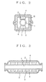
- FIG. 2 is a center section view of the water activating apparatus according to the embodiment
- FIG. 3 is a longitudinal section view thereof.
- Nd-Fe-B-type permanent magnets 3 are arranged so that the magnets of each pair are placed above and below the water flow tube 1 with the N pole and the S pole being opposed to each other.
- copper plates 10 of non-magnetic conductive metal are provided as a pair at the right and left sides of the water flow tube 1.
- the yokes 4 are provided as a pair outside the copper plates 10 so as to make a contact with the copper plates 10 and the permanent magnets 3.
- the above-described components are accommodated in a box 11.
- the outer surface of this box 11 is covered with a chrome metal plate, which is strongly diamagnetic.
- Permanent Magnet Type Nd-Fe-B (neodymium-iron-boron) type Residual magnetic flux density: 12,400 gausses Magnetic field: In-plane magnetic field The number of units: 8 (4 pairs) Distance between N-S magnetic poles: 26 mm Non-magnetic conductive metal plate Type: Copper Distance between polar plates: 26 mm Yoke Type: Iron Thickness: 5 mm Water flow tube Type: Hard polyvinyl chloride Size: Caliber 20 mm ⁇ Box Material: Hard polyurethane resin externally coated with chrome metal plate
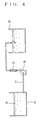
- FIGS. 2 and 3 With the use of the water activating apparatus according to the present invention illustrated in FIGS. 2 and 3 to form a configuration illustrated in FIG. 4, a water activating process was performed to compare processed water with untreated water in oxidation-reduction potential, pH (potential of hydrogen), the number of minus ions, BOD (biochemical oxygen demand), general viable cell count, etc.
- untreated raw water 16 of 200 l is put in a water tank 14 with a hard polyvinyl chloride tube 17 being installed thereon, and is then poured into a water tank 15 by a pump 18 provided on its way.
- An water activating apparatus 12 according to the present embodiment is provided between the pump 18 and the water tank 15. The water after a one-pass process was compared with the untreated water.
- the oxidation-reduction potential was reduced by approximately 81%, from 275 mV of the original tap water to 223 mV after the one-pass process. With this, the processed water absorbs electrons, thereby increasing its reducing power and bipolarity.
- water can be significantly activated with synergy of the magnetic force and the electronic force, thereby obtaining water of a far higher degree of activation than that obtained in the conventional scheme using only the magnetic force. Also, in the structure of the apparatus, a portion for generating a magnetic field and electrons does not make a contact directly with water. Therefore, the possibility of water leakage and the like can be totally eliminated. This activation achieves microclustered water, thereby obtaining good and highly-purified water.
Landscapes
- Life Sciences & Earth Sciences (AREA)
- Hydrology & Water Resources (AREA)
- Engineering & Computer Science (AREA)
- Environmental & Geological Engineering (AREA)
- Water Supply & Treatment (AREA)
- Chemical & Material Sciences (AREA)
- Organic Chemistry (AREA)
- Water Treatment By Electricity Or Magnetism (AREA)
Priority Applications (1)
| Application Number | Priority Date | Filing Date | Title |
|---|---|---|---|
| EP04005572A EP1574480A1 (de) | 2004-03-09 | 2004-03-09 | Verfahren und Vorrichtung zur Aktivierung von Wasser mit Permanentmagneten |
Applications Claiming Priority (1)
| Application Number | Priority Date | Filing Date | Title |
|---|---|---|---|
| EP04005572A EP1574480A1 (de) | 2004-03-09 | 2004-03-09 | Verfahren und Vorrichtung zur Aktivierung von Wasser mit Permanentmagneten |
Publications (1)
| Publication Number | Publication Date |
|---|---|
| EP1574480A1 true EP1574480A1 (de) | 2005-09-14 |
Family
ID=34814276
Family Applications (1)
| Application Number | Title | Priority Date | Filing Date |
|---|---|---|---|
| EP04005572A Withdrawn EP1574480A1 (de) | 2004-03-09 | 2004-03-09 | Verfahren und Vorrichtung zur Aktivierung von Wasser mit Permanentmagneten |
Country Status (1)
| Country | Link |
|---|---|
| EP (1) | EP1574480A1 (de) |
Cited By (6)
| Publication number | Priority date | Publication date | Assignee | Title |
|---|---|---|---|---|
| CN102863113A (zh) * | 2012-10-10 | 2013-01-09 | 苏润西 | 一种磁场与离子交换膜组成的离子分离装置和方法 |
| CN106904682A (zh) * | 2017-04-10 | 2017-06-30 | 中科圣泉(深圳)生物有限公司 | 一种非接触式分子低频共振活化水装置 |
| CN108699353A (zh) * | 2016-03-04 | 2018-10-23 | 神田智 | 涂覆液生成装置及涂覆装置 |
| CN112225329A (zh) * | 2020-11-02 | 2021-01-15 | 张贵宝 | 循环水活化装置 |
| CN113105061A (zh) * | 2021-04-15 | 2021-07-13 | 河北大学 | 一种在常压下制备超饱和长效磁化富氢溶液的装置及方法 |
| CN113582304A (zh) * | 2021-08-25 | 2021-11-02 | 蒋惠祥 | 活水装置、活水系统及活水方法 |
Citations (4)
| Publication number | Priority date | Publication date | Assignee | Title |
|---|---|---|---|---|
| DE3503691A1 (de) * | 1985-02-04 | 1986-08-07 | Heinrich 8673 Rehau Kunel | Magnet-aktivator |
| JPH11138173A (ja) * | 1997-11-11 | 1999-05-25 | Tadashi Mochizai | 水の活性化方法及びそのための装置 |
| JP2002086153A (ja) * | 2000-09-14 | 2002-03-26 | Tadashi Mochizai | 水の活性化方法及びそのための装置 |
| US20040031759A1 (en) * | 2002-02-13 | 2004-02-19 | Richard Gordon L. | Method and apparatus for separating lons from a fluid stream |
-
2004
- 2004-03-09 EP EP04005572A patent/EP1574480A1/de not_active Withdrawn
Patent Citations (4)
| Publication number | Priority date | Publication date | Assignee | Title |
|---|---|---|---|---|
| DE3503691A1 (de) * | 1985-02-04 | 1986-08-07 | Heinrich 8673 Rehau Kunel | Magnet-aktivator |
| JPH11138173A (ja) * | 1997-11-11 | 1999-05-25 | Tadashi Mochizai | 水の活性化方法及びそのための装置 |
| JP2002086153A (ja) * | 2000-09-14 | 2002-03-26 | Tadashi Mochizai | 水の活性化方法及びそのための装置 |
| US20040031759A1 (en) * | 2002-02-13 | 2004-02-19 | Richard Gordon L. | Method and apparatus for separating lons from a fluid stream |
Non-Patent Citations (2)
| Title |
|---|
| PATENT ABSTRACTS OF JAPAN vol. 1999, no. 10 31 August 1999 (1999-08-31) * |
| PATENT ABSTRACTS OF JAPAN vol. 2002, no. 07 3 July 2002 (2002-07-03) * |
Cited By (8)
| Publication number | Priority date | Publication date | Assignee | Title |
|---|---|---|---|---|
| CN102863113A (zh) * | 2012-10-10 | 2013-01-09 | 苏润西 | 一种磁场与离子交换膜组成的离子分离装置和方法 |
| CN102863113B (zh) * | 2012-10-10 | 2016-08-10 | 苏润西 | 一种磁场与离子交换膜组成的离子分离装置和方法 |
| CN108699353A (zh) * | 2016-03-04 | 2018-10-23 | 神田智 | 涂覆液生成装置及涂覆装置 |
| CN106904682A (zh) * | 2017-04-10 | 2017-06-30 | 中科圣泉(深圳)生物有限公司 | 一种非接触式分子低频共振活化水装置 |
| CN112225329A (zh) * | 2020-11-02 | 2021-01-15 | 张贵宝 | 循环水活化装置 |
| CN113105061A (zh) * | 2021-04-15 | 2021-07-13 | 河北大学 | 一种在常压下制备超饱和长效磁化富氢溶液的装置及方法 |
| CN113105061B (zh) * | 2021-04-15 | 2022-08-26 | 河北大学 | 一种在常压下制备超饱和长效磁化富氢溶液的装置及方法 |
| CN113582304A (zh) * | 2021-08-25 | 2021-11-02 | 蒋惠祥 | 活水装置、活水系统及活水方法 |
Similar Documents
| Publication | Publication Date | Title |
|---|---|---|
| CN1137854C (zh) | 水的磁化处理装置 | |
| KR20030074069A (ko) | 자기적으로 처리된 물을 생성하는 장치 및 액체 연료를자기적으로 처리하는 장치 | |
| JP3992583B2 (ja) | 水の活性化方法および活性化装置 | |
| US7090776B2 (en) | Method and apparatus for activating water | |
| EP1574480A1 (de) | Verfahren und Vorrichtung zur Aktivierung von Wasser mit Permanentmagneten | |
| US5118416A (en) | Permanent magnetic power cell circuit for treating fluids to control iron pipes | |
| US20100084274A1 (en) | Fluid treatment device for fluid activation | |
| KR100620433B1 (ko) | 물의 활성화 방법 및 그 장치 | |
| JP7113426B2 (ja) | 水の活性化装置及び活性化方法 | |
| JP4523015B2 (ja) | 水のイオン電荷化装置 | |
| EP2287515A2 (de) | Vorrichtung zur elektrobehandlung von flüssigkeiten | |
| JP4327847B2 (ja) | 流体の活性化装置 | |
| KR100821721B1 (ko) | 대용량 자화수 발생장치 | |
| JPH11128918A (ja) | 水処理装置 | |
| JP4637051B2 (ja) | 水の活性化方法および活性化装置 | |
| JP4791237B2 (ja) | 冷却水処理装置 | |
| JPH11156365A (ja) | 電磁場水処理装置 | |
| CN110759440A (zh) | 一种絮凝反应装置 | |
| CN210012637U (zh) | 一种具有三维电极的电解处理装置 | |
| WO2016203604A1 (ja) | 洗浄装置及びその洗浄方法 | |
| JP3215903U (ja) | 液体活性化装置及び洗浄液生成装置 | |
| JP2005238070A (ja) | 水の磁気処理装置 | |
| JPH11169859A (ja) | 電磁場水処理装置 | |
| JP3416591B2 (ja) | 水処理装置 | |
| JPH09294995A (ja) | 排水処理装置 |
Legal Events
| Date | Code | Title | Description |
|---|---|---|---|
| PUAI | Public reference made under article 153(3) epc to a published international application that has entered the european phase |
Free format text: ORIGINAL CODE: 0009012 |
|
| AK | Designated contracting states |
Kind code of ref document: A1 Designated state(s): AT BE BG CH CY CZ DE DK EE ES FI FR GB GR HU IE IT LI LU MC NL PL PT RO SE SI SK TR |
|
| AX | Request for extension of the european patent |
Extension state: AL LT LV MK |
|
| 17P | Request for examination filed |
Effective date: 20051130 |
|
| AKX | Designation fees paid |
Designated state(s): AT BE BG CH CY CZ DE DK EE ES FI FR GB GR HU IE IT LI LU MC NL PL PT RO SE SI SK TR |
|
| STAA | Information on the status of an ep patent application or granted ep patent |
Free format text: STATUS: THE APPLICATION IS DEEMED TO BE WITHDRAWN |
|
| 18D | Application deemed to be withdrawn |
Effective date: 20091107 |