The present invention relates to methods and apparatuses
for activating water and, particularly, to a method of activating
water over a wide range from supplied clean water and gray water
to drain water and an apparatus for activating such water.
A scheme of activating water by splitting molecular
population of water with the use of a magnetic force to reduce
the size of a cluster (molecular assembly) of water has been well
known. For example, there have been a system for activation in
which water reserved in a reservoir is processed by a filtration
unit and a magnetic processing unit (refer to Japanese Patent
Laid-Open Publication No. 2002-254082, pp. 2-6, FIG. 1), an
apparatus for activating a flow of water in which a permanent magnet
is attached to the outside of a water flow tube and an image magnet
is formed symmetrically to the surface of the water flow tube (refer
to Japanese Patent Laid-Open PublicationNo. 2002-192159, pp. 2-3,
FIG. 1), an apparatus in which counterclockwise magnetic lines
of force and clockwise magnetic lines of force are alternately
generated and a flow of water is allowed to pass through the generated
magnetic lines of force for activation (refer to Japanese Patent
Laid-Open Publication No. 2002-66566, pp. 3-5, FIG. 4), etc. As
such, in general, activation is performed by allowing water to
pass between the S pole and the N pole of at least a pair of magnets.
In order to more efficiently perform activation by using
these schemes, however, it is required to use strong magnets. Other
than intensifying the magnetic force, there is no way to improve
the efficiency of water activation. Therefore, the degree of
activation is disadvantageously low and insufficient.
In order to solve the above disadvantage, the inventor of
the present invention has previously suggested a water activating
method in which the S pole and the N pole are opposed to each other
and, for the purpose of efficient activation, a non-magnetic
conductive metal plate is used to cause an electromotive current
occurring in a direction perpendicular to a flow of water to
repulsively act, thereby acting electrons and also a magnetic force
upon the flow of water, and an apparatus for this method (refer
to Japanese Patent Laid-Open Publication No. 11-138173, pp. 2-5,
FIG. 1). This apparatus has a structural problem, however, that
a carbon electrode has to be fitted into the water flow tube, thereby
disadvantageously causing an inconvenience of adherence for the
purpose of preventing water leakage.
As has been described above, the conventional water
activating apparatuses have the problem that there is no way to
improve the efficiency of water activation other than intensifying
the magnetic force. In order to solve this problem, the inventor
has previously suggested the above-described method and apparatus,
which, however, have the problem in view of the structure for
preventing water leakage.
Therefore, an object of the present invention is to achieve
a water activating apparatus which solves the above-described
problems, the water activating apparatus having a relatively simple
structure without the possibility of water leakage and achieving
highly efficient activation, and is also to achieve an activating
method used for the water activating apparatus.
In order to attain the above object, a water activating
method according to the present invention is characterized in that
at least one pair of permanent magnets with an N pole and an S
pole thereof being opposed to each other is provided across a water
flow tube, concave yokes in a pair that are formed by molding magnetic
metal or magnetic ceramic are arranged so as to be opposed to each
other with a predetermined gap therebetween and each to
magnetically make a contact with a surface of one of the permanent
magnets opposite to a surface thereof that is opposed to another
one of the permanent magnets, a non-magnetic conductive metal layer
is laminated inside the concave yokes including the gap
therebetween and excluding contact areas that make a contact with
the permanent magnets, the non-magnetic conductive metal layer
being formed by single plating made of either one of metals of
copper, silver, and gold or composite plating made of the metals,
or a composite metal plate formed by laminating films made of the
metals, thereby improving an electric potential inside the pair
of the concave yokes, with water passing through the water flow
tube, an electromotive current occurring in a direction
perpendicular to a direction of a flow of water and a direction
of magnetic lines of force occurring between the permanent magnets
is caused to repulsively act by an electric potential inside the
yokes in a longitudinal direction of the water flow tube, thereby
performing a process by causing electrons and a magnetic force
occurring between the permanent magnets to act upon the flow of
water in the water flow tube.
With this, magnetic activation by the permanent magnets
and electrochemical activation by electrons are performed. Thus,
with synergy of the magnetic force and the electronic force, more
efficient activation can be achieved at a higher degree compared
with an activating scheme merely with the magnetic force. Also,
a water activating method without the possibility of water leakage
can be obtained.
Also, an apparatus according to the present invention is
characterized by including at least one pair of concave yokes formed
by molding magnetic metal or magnetic ceramic; an N pole formed
by a permanent magnet provided so as to magnetically make a contact
with an inner surface of one of the concave yokes; and an S pole
formed by a permanent magnet provided so as to magnetically make
a contact with an inner surface of another one of the concave yokes,
the concave yokes being arranged so as to have a predetermined
gap with the N pole and the S pole being opposed to each other,
a non-magnetic conductive metal layer being laminated inside the
concave yokes including the gap therebetween and excluding contact
areas that make a contact with the permanent magnets, the
non-magnetic conductive metal layer being formed by single plating
made of either one of metals of copper, silver, and gold or composite
plating made of the metals, or a composite metal plate formed by
laminating films made of the metals, and a non-magnetic water flow
tube being provided between the N pole and the S pole that are
opposed to each other to allow a flow of water to pass therethrough
in a direction perpendicular to a direction of magnetic lines of
force from the N pole to the S pole, thereby activating the flow
of water.
With this, magnetic activation by the permanent magnets
and electrochemical activation by electrons are performed. Thus,
with synergy of the magnetic force and the electronic force, more
efficient activation can be achieved at a higher degree compared
with an activating scheme merely with the magnetic force. Also,
a water activating apparatus without the possibility of water
leakage can be obtained.
Furthermore, the present activating apparatus is
characterized in that a box is provided for accommodating the
concave yokes including a part of the water flow tube, and an outer
surface of the box is covered with either one of chrome plating
and a chrome metal plate made of strong diamagnetic metal.
With this, it is possible to achieve a water activating
apparatus capable of blocking the magnetic lines of force without
external leakage and causing the magnetic force to more effectively
act upon the flow of water.
Still further, the present activating apparatus is
characterized in that the non-magnetic conductive metal layer is
formed by either one of composite plating and a composite metal
plate formed by metals of different electric potentials, with a
high-potential metal being positioned on a side of the water flow
tube.
With this, it is possible to achieve a water activating
apparatus capable of promoting emission of electrons by contact
cell reaction and causing electrons to more effectively act upon
the flow of water.
Still further, the present activating apparatus is
characterized in that the flow of water passing through the water
flow tube is kept from contact with the concave yokes and the
non-magnetic conductive metal layer.
With this, it is possible to achieve a water activating
apparatus in which the possibility of water leakage is completely
eliminated.
An activating apparatus according to the present embodiment
is described in detail below with reference to the drawings.
FIG. 1 is a perspective section view illustrating the
internal structure of a water activating apparatus according to
the present invention.
In FIG. 1, 1 denotes a water flow pipe, 2 denotes an N pole
of a permanent magnet, 3 denotes an S pole of another permanent
magnet, 4 denotes concave yokes, 5 denotes ends of each concave
yoke 4, 6 denotes polarities transferred to the ends of the concave
yokes 4, 7 denotes a direction of magnetic lines of force, 8 denotes
a direction of a flow of water, 9 denotes a direction of an
electromotive current, and 10 denotes a non-magnetic conductive
metal layer.
The N pole 2 of the permanent magnet and the S pole 3 of
the other permanent magnet are vertically arranged above and below
the water flow tube 1 so as to be opposed to each other. The concave
yokes 4 are formed by molding magnetic metal or magnetic ceramic,
with one yoke being attached to encase the N pole 2 of the permanent
magnet and the other yoke being attached to encase the S pole 3
of the other permanent magnet. The concave yokes 4 are vertically
opposed to each other, and have a gap therebetween so as not to
make a contact at their ends with each other.
Thus, since one side of the permanent magnet is attached
to the concave yoke 4, the polarity of that side of the permanent
magnet is transferred to both ends of the concave yoke 4 facing
the gap. Through such polarity transfer, the N pole 6 at the end
of one concave yoke 4 and the S pole 6 at the end of the other
concave yoke 4 are attracted to each other, thereby forming a
magnetic circuit preventing leakage of the magnetic lines of force
to the outside of the concave yokes 4.
With the above structure, when the flow of water passes
through the magnetic lines of force in the direction 8 indicated
by an arrow, an electromotive current occurs in the direction 9
indicated by another arrow which is horizontal and perpendicular
to the flow of water.
The electromotive current has an intensity E proportional
to a magnetic flux density B and a flow speed V of the flow of
water, which can be represented by the following equation:
E = kBV,
where E is the intensity of the electromotive current, k is a constant,
B is the magnetic flux density, and V is a flow speed of the flow
of water.
For the purpose of performing induction charging of the
electromotive current occurring in the above-described manner
without discharge loss and efficiently emitting electrons
occurring due to this charging into the flow of water, the
non-magnetic conductive metal layer 10 is provided inside the
concave yokes 4. The non-magnetic conductive metal layer 10 is
formed by metal with a high electric potential, such as single
plating made of either one of copper, silver, and gold that belong
to Group IB of the periodic table or composite plating made of
these metals, or a composite metal plate formed by laminating films
made of these metals. With the non-magnetic conductive metal
layer 10 having a property of pressing the magnetic lines of force
to the center, the magnetic lines of force become highly dense
and the magnetic flux density B becomes increased, thereby
increasing the occurrence of the electromotive current.
Furthermore, the electromotive current occurred is blocked and
cannot pass through the non-magnetic conductive metal layer 10.
Also, the non-magnetic conductive metal layer 10 is higher
in electric potential than magnetic metal or magnetic ceramic
forming the concave yokes 4. Therefore, with contact cell reaction,
the electric potential at the center of the inside of the
non-magnetic conductive metal layer 10 becomes further increased,
thereby more efficiently causing the electrons to repulsively act
for emission into the flow of water.
If being formed by composite metal or a composite metal
plate, the non-magnetic conductive metal layer 10 is formed by
jointing a high-potential metal and a low-potential metal together,
with the high-potential metal being positioned on a side of the
water flow tube 1. Thus, emission of more electrons are promoted.
The electrons emitted into the flow of water provide charges
to oxygen, which is a part of a molecule of water (H2O) and is
an electron acceptor, thereby increasing the bipolarity of water.
This widens the bond angle formed by the hydrogen atoms, and
therefore increases the density of water molecules and reduces
the size of a molecular assembly (cluster) of water. The flow
of water becomes negatively charged with its oxidation-reduction
potential being lowered, and thus becomes a return flow to promote
water activation.
The occurrence of clusters is caused by hydrogen bonding.
When the water becomes electronically rich, electrons in the
hydrogen atoms of the water molecule and free electrons repulsively
act each other. When this repulsive force becomes higher than
the van der Waals bond of force of water, hydrogen bonding is cut
out to produce microclusters, thereby activating the Brownian
movement of water molecules. Simultaneously, an electron emitted
into the flow of water is bonded to dissolved oxygen in the water
to form anionic oxygen (O + e- → O-), which reacts with the water
to yield hydroxyl radical (O- + H2O = 2OH), thereby slightly
alkalizing the water to be processed.
With this, by using the water activating apparatus according
to the present invention, magnetic activation by permanent magnets
and electrochemical activation by electrons are performed. Thus,
with synergy of a magnetic force and an electronic force, far
superior activation can be performed compared with an activating
scheme merely with a magnetic force.
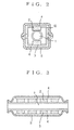
An embodiment of the water activating apparatus according
to the present invention is described below with reference to
FIGS. 2 and 3. FIG. 2 is a center section view of the water
activating apparatus according to the embodiment, and FIG. 3 is
a longitudinal section view thereof.
As illustrated in the drawings, four pairs of Nd-Fe-B-type
permanent magnets 3 are arranged so that the magnets of each pair
are placed above and below the water flow tube 1 with the N pole
and the S pole being opposed to each other. Also, copper plates 10
of non-magnetic conductive metal are provided as a pair at the
right and left sides of the water flow tube 1. Furthermore, the
yokes 4 are provided as a pair outside the copper plates 10 so
as to make a contact with the copper plates 10 and the permanent
magnets 3. The above-described components are accommodated in
a box 11. The outer surface of this box 11 is covered with a chrome
metal plate, which is strongly diamagnetic.
Specifications of the present embodiment are as shown in
Table 1.
| Permanent Magnet | Type: Nd-Fe-B (neodymium-iron-boron) type
Residual magnetic flux density: 12,400 gausses
Magnetic field: In-plane magnetic field
The number of units: 8 (4 pairs)
Distance between N-S magnetic poles: 26 mm |
| Non-magnetic conductive metal plate | Type: Copper
Distance between polar plates: 26 mm |
| Yoke | Type: Iron
Thickness: 5 mm |
| Water flow tube | Type: Hard polyvinyl chloride
Size: Caliber 20 mm |
| Box | Material: Hard polyurethane resin externally coated with chrome metal plate |
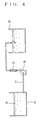
With the use of the water activating apparatus according
to the present invention illustrated in FIGS. 2 and 3 to form a
configuration illustrated in FIG. 4, a water activating process
was performed to compare processed water with untreated water in
oxidation-reduction potential, pH (potential of hydrogen), the
number of minus ions, BOD (biochemical oxygen demand), general
viable cell count, etc. In the configuration of FIG. 4, untreated
raw water 16 of 200 l is put in a water tank 14 with a hard polyvinyl
chloride tube 17 being installed thereon, and is then poured into
a water tank 15 by a pump 18 provided on its way. An water activating
apparatus 12 according to the present embodiment is provided
between the pump 18 and the water tank 15. The water after a one-pass
process was compared with the untreated water.
The results of the processing test were as shown in Table 2
through Table 5.
| Raw water: Tap water |
| | Oxidation-reduction potential |
| Untreated water | 275 mV |
| Water after one-pass process | 223 mV |
| Raw water: Tap water |
| | pH |
| Untreated water | 7.2 |
| Water after one-pass process | 7.8 |
| Raw water: Fish processing drain water |
| | BOD |
| Untreated water | 1500 mg |
| Water after one-pass process | 400 mg |
| Raw water: Gulf seawater |
| | Viable cell count | Coliform bacteria count |
| Untreated water | 480/ml | 6000/ml |
| Water after one-pass process | 48/ml | 0/ml |
As evident from the above Table 2, with the use of the water
activating apparatus according to the present invention, the
oxidation-reduction potential was reduced by approximately 81%,
from 275 mV of the original tap water to 223 mV after the one-pass
process. With this, the processed water absorbs electrons,
thereby increasing its reducing power and bipolarity.
Also, as evident from Table 3, pH was changed from 7.2 of
the original tap water to 7.8 after the one-pass process with more
alkalinity. This indicates a high occurrence of hydroxyl radical.
Furthermore, as evident from Table 4, the contaminated fish
processing drain water with BOD of 15000 mg/l was dramatically
improved to BOD of 400 mg/l after the one-pass process. Still
further, as evident from Table 5, almost all the viable cells and
coliform bacteria in the gulf seawater were eliminated by the
one-pass process. As such, the present apparatus is quite
effective in activating water and improving water quality.
As has been described in the foregoing, according to the
present invention, water can be significantly activated with
synergy of the magnetic force and the electronic force, thereby
obtaining water of a far higher degree of activation than that
obtained in the conventional scheme using only the magnetic force.
Also, in the structure of the apparatus, a portion for generating
a magnetic field and electrons does not make a contact directly
with water. Therefore, the possibility of water leakage and the
like can be totally eliminated. This activation achieves
microclustered water, thereby obtaining good and highly-purified
water.
Description of Reference Numerals
- 1
- water flow tube
- 2
- N pole of a permanent magnet
- 3
- S pole of the permanent magnet
- 4
- concave yoke
- 5
- end of the concave yoke
- 6
- transferred polarity of the concave yoke
- 7
- direction of magnetic lines of force
- 8
- direction of a flow of water
- 9
- direction of a electromotive current
- 10
- non-magnetic conductive metal layer
- 11
- box
- 12
- activating apparatus
- 14, 15
- water tank
- 16
- raw water
- 17
- hard polyvinyl chloride tube
- 18
- pump