EP1574469B1 - Méthode pour développer le régulateur d'un système antichoc de cabine d'ascenseur - Google Patents
Méthode pour développer le régulateur d'un système antichoc de cabine d'ascenseur Download PDFInfo
- Publication number
- EP1574469B1 EP1574469B1 EP20050001167 EP05001167A EP1574469B1 EP 1574469 B1 EP1574469 B1 EP 1574469B1 EP 20050001167 EP20050001167 EP 20050001167 EP 05001167 A EP05001167 A EP 05001167A EP 1574469 B1 EP1574469 B1 EP 1574469B1
- Authority
- EP
- European Patent Office
- Prior art keywords
- controller
- model
- acceleration
- cabin
- frequency responses
- Prior art date
- Legal status (The legal status is an assumption and is not a legal conclusion. Google has not performed a legal analysis and makes no representation as to the accuracy of the status listed.)
- Expired - Lifetime
Links
- 238000000034 method Methods 0.000 title claims description 25
- 238000013461 design Methods 0.000 title claims description 15
- 230000035939 shock Effects 0.000 title 1
- 230000001133 acceleration Effects 0.000 claims description 39
- 230000004044 response Effects 0.000 claims description 25
- 238000013016 damping Methods 0.000 claims description 14
- 238000012546 transfer Methods 0.000 claims description 10
- 238000005457 optimization Methods 0.000 claims description 6
- 230000001419 dependent effect Effects 0.000 claims description 5
- 239000011159 matrix material Substances 0.000 description 9
- 238000005259 measurement Methods 0.000 description 7
- 230000000694 effects Effects 0.000 description 4
- 238000001228 spectrum Methods 0.000 description 4
- 230000008878 coupling Effects 0.000 description 3
- 238000010168 coupling process Methods 0.000 description 3
- 238000005859 coupling reaction Methods 0.000 description 3
- 230000005540 biological transmission Effects 0.000 description 2
- 230000008859 change Effects 0.000 description 2
- 238000010586 diagram Methods 0.000 description 2
- 230000005284 excitation Effects 0.000 description 2
- 230000005484 gravity Effects 0.000 description 2
- 238000005096 rolling process Methods 0.000 description 2
- 230000003068 static effect Effects 0.000 description 2
- 230000008901 benefit Effects 0.000 description 1
- 238000004364 calculation method Methods 0.000 description 1
- 230000006835 compression Effects 0.000 description 1
- 238000007906 compression Methods 0.000 description 1
- 230000007423 decrease Effects 0.000 description 1
- 238000012938 design process Methods 0.000 description 1
- 238000011161 development Methods 0.000 description 1
- 230000018109 developmental process Effects 0.000 description 1
- 230000004069 differentiation Effects 0.000 description 1
- 229920001971 elastomer Polymers 0.000 description 1
- 239000000806 elastomer Substances 0.000 description 1
- 238000009413 insulation Methods 0.000 description 1
- 238000003754 machining Methods 0.000 description 1
- 230000009022 nonlinear effect Effects 0.000 description 1
- 230000036316 preload Effects 0.000 description 1
- 230000008569 process Effects 0.000 description 1
- 238000011160 research Methods 0.000 description 1
- 238000012360 testing method Methods 0.000 description 1
- 230000009466 transformation Effects 0.000 description 1
Images


Classifications
-
- B—PERFORMING OPERATIONS; TRANSPORTING
- B66—HOISTING; LIFTING; HAULING
- B66B—ELEVATORS; ESCALATORS OR MOVING WALKWAYS
- B66B7/00—Other common features of elevators
- B66B7/02—Guideways; Guides
- B66B7/04—Riding means, e.g. Shoes, Rollers, between car and guiding means, e.g. rails, ropes
- B66B7/041—Riding means, e.g. Shoes, Rollers, between car and guiding means, e.g. rails, ropes including active attenuation system for shocks, vibrations
-
- B—PERFORMING OPERATIONS; TRANSPORTING
- B66—HOISTING; LIFTING; HAULING
- B66B—ELEVATORS; ESCALATORS OR MOVING WALKWAYS
- B66B7/00—Other common features of elevators
- B66B7/02—Guideways; Guides
- B66B7/04—Riding means, e.g. Shoes, Rollers, between car and guiding means, e.g. rails, ropes
- B66B7/046—Rollers
Definitions
- the invention relates to a method for the design of a vibration damping controller on an elevator car, wherein the controller design is based on a model of the elevator car.
- a multi-size controller and another multi-size controller for maintaining the game on the guide rollers or the upright position of the elevator car are provided.
- the control signals of the two controllers are added together and control one actuator per roller guide and per horizontal direction.
- the controller design is based on a model of the elevator car, which takes into account the essential structural resonances.
- the disadvantage is that the overall model tends to great complexity, despite sophisticated methods for reducing the number of poles. As a result, the model-based controller also becomes complex.
- the invention aims to remedy this situation.
- the invention as characterized in claim 1 solves the problem of avoiding the disadvantages of the known method and to propose a simple method for the design of a regulator.
- an overall model of the elevator car with a known structure is specified. It is a so-called multi-body system (MBS) model, which includes several rigid bodies.
- MKS model describes the essential elastic structure of the elevator car with the guide rollers and the actuators as well as the force coupling with the guide rails.
- the model parameters are more or less well known or there are estimates, the parameters for the elevator car used to be identified or to be determined.
- the transfer functions or frequency responses of the model are compared with the measured transfer functions or frequency responses. Using an algorithm to optimize functions with several variables are used to modify the estimated model parameters to achieve the greatest possible match.
- the active vibration damping system of the elevator car itself can be used as a measuring device for the transmission functions or frequency responses to be measured. With the actuators, the elevator car is excited and with the acceleration sensors or with the position sensors, the answers are measured.
- This model-based design method of the controller ensures the best possible active vibration damping for the individual elevator cars with very different parameters.
- the above-mentioned identification method ensures that the result is the simplest and most consistent model of the elevator car.
- the controller based on this model has a better quality or a better control quality.
- the process is systematically writable and can be largely automated and carried out in a much shorter time.
- a robust multi-size controller is designed to reduce the acceleration and a position controller to maintain the game on the guide rollers.
- the acceleration controller has the behavior of a bandpass filter and the best effect in a medium Frequency range from about 1 Hz to 4 Hz. Below and above this frequency band, the gain and thus the efficiency of the acceleration controller is reduced.
- the effect of the acceleration controller is limited by the available clearance on the guide rollers and the position controller to be interpreted thereon.
- the position controller causes the elevator car to track an average of the rail profiles while the acceleration controller is causing a linear movement.
- This target conflict is solved by the two controllers in different frequency ranges are effective.
- the gain of the positioner is large at low frequencies and then decreases. That is, it has the property of a low-pass filter.
- the accelerator controller has a small gain at low frequencies.
- the effect of the acceleration controller is limited by the elasticity of the elevator car.
- the first structural resonance can occur, for example, at 12 Hz, this value being highly dependent on the design of the elevator car and can be significantly lower. Above the first structural resonance, the controller can no longer reduce the acceleration on the cabin body. There is even a risk that structural resonances are stimulated or that instability can occur. With knowledge of the dynamic system model of the controlled system, the controller can be designed so that this can be avoided.
- the MKS model must reproduce the essential characteristics of the elevator car with regard to ride comfort. Since it is only possible to work with linear models when identifying the parameters, all nonlinear effects must be neglected.
- the first natural frequencies of the elastic elevator car are so deep that they can overlap with the so-called rigid body natural frequencies of the entire cabin.
- At least two rigid bodies are required for modeling the elastic elevator car 1, namely the cab body 2 and the cab frame 3.
- Cabin body 2 and cab frame 3 are connected by means of elastomer springs 4.1 to 4.6, the so-called cab insulation 4. This reduces the transmission of structure-borne noise from the frame to the frame Cab body.
- a rigid elevator car it is sufficient to consider the cabin body and cabin frame as a whole as a whole.
- the transverse stiffness of cab body 2 and cab frame 3 is substantially less than the rigidity in the vertical direction.
- This can be modeled with the division into at least two rigid bodies, namely cabin bodies 2.1 and 2.2 and cabin frames 3.1 and 3.2.
- the at least two sub-bodies are horizontally coupled by springs 5, 6.1 and 6.2 and can be considered vertically connected as rigid.
- the guide rollers 7.1 to 7.8 with the proportional masses of levers and actuators can be modeled with at least 8 rigid bodies or even neglected. This depends on the associated natural frequencies of the guide rollers and on the upper limit of the frequency range considered. Since the natural frequency of the actuator-roller system in the controlled state can lead to instability, modeling with rigid bodies is preferred. These are only displaceable perpendicular to the footprint on the rail relative to the frame and coupled to the roller guide springs 8.1 to 8.8. In the other directions they are rigidly connected to the frame.
- Fig. 2 shown is the leadership behavior or the power coupling between guide rollers and guide rails important. To model essentially only the two horizontal force components are necessary. The vertical force component resulting from the rolling resistance can be neglected. The normal force results from the elastic compression of the roller covering 9.1 to 9.8. The axial or transverse force results from the angle between the straight line perpendicular to the roller axis and parallel to the rail and the actual direction of movement of the roller center.
- the force law ⁇ 1 ⁇ becomes invalid at the latest when the limits of the static friction force are reached and at a large slip angle ⁇ . This becomes faster at low driving speed and is about 90 degrees at standstill.
- the force law ⁇ 1 ⁇ only applies to the moving cab.
- v K and F RN can be considered constant if the preload force is significantly greater than the dynamic part of the normal force. This means that the roller force in the axial direction is proportional and opposite to the speed in the axial direction and inversely proportional to the driving speed of the elevator car.
- Transverse vibrations of the cabin are thus damped by the rollers as from a viscous damper, the effect is smaller with increasing speed.
- the guide rollers 7 are connected to a about an axis 10 'rotatable lever 10 to the cabin frame 3, wherein the roller guide spring 8 generates a force between the lever and the cabin frame.
- An actuator 11 generates a force which acts parallel to the roller guide spring.
- a position sensor 12 measures the position of the lever 10 and the guide roller 7, respectively.
- An acceleration sensor 13 measures the acceleration of the car frame 3 perpendicular to the contact surface of the roller covering 9 on the guide rail 14.
- the reference number of the respective element is as in FIG Fig. 1 shown (for example, at the elevator car 1 bottom right: 7.1.8.1.9.1,10.1,11.1,12.1,13.1).
- the number of required acceleration sensors 13 corresponds to the number of controlled axes, wherein at least three and at most six acceleration sensors are provided.
- the number of axles is reduced from eight to six, or from four to three axles, if only down active is controlled.
- An i is a triple of signals Fn i , Pn i , i for actuator force, position and acceleration.
- the index i is the consecutive numbering in the respective axis system and n stands for number of axes of the system.
- the frequency spectrum of the force signals and the measured position signals and acceleration signals are determined by Fourier transformation.
- the transfer functions in the frequency domain or frequency responses G i , j ( ⁇ ) with the angular frequency ⁇ as an argument are determined by dividing the spectra of the measurements by the associated spectrum of the force signal.
- i the index of the measurement
- j the index of the force.
- G P i , j ( ⁇ ) are the individual frequency responses from force to position and G a i , j ( ⁇ ) are the individual frequency responses of Power to acceleration.
- the matrix G P ( ⁇ ) contains all the frequency responses force to position and matrix G a ( ⁇ ) all
- Matrix G ( ⁇ ) arises from the vertical composition of G P ( ⁇ ) and G a ( ⁇ ).
- the vector ⁇ contains the derivatives of x after the time.
- y is a vector containing the measured quantities, ie positions and accelerations.
- the vector u contains the inputs (actuator forces) of the system.
- A, B, C and D are matrices which together form the so-called Jacobian matrix by which a linear system is completely described.
- G ⁇ ( ⁇ ) is a matrix with the same number of rows as measurements in vector y and the same number of columns as inputs in vector u and contains all frequency responses of the MKS model of the cabin.
- a Jacobian matrix contains all the partial derivatives of a system of equations. For a linear system of coupled 1st order differential equations, these are the constant coefficients of the A, B, C, and D matrices.
- the model contains a number of well known parameters such as dimensions and mass and a number of poorly known parameters such as spring rates and damping constants. It is important to identify these poorly known parameters.
- the identification is performed by comparing the frequency responses of the model with the measured frequency responses. With an optimization algorithm, the poorly known model parameters are changed until the minimum of the sum e of all deviations of the frequency responses of the model from the measured frequency responses is found.
- w ( ⁇ ) is a frequency-dependent weighting. It ensures that only important parts of the measured frequency responses are modeled in the model.
- An optimization algorithm can be briefly rewritten as follows: Given is a function with multiple variables. We are looking for a minimum or maximum of this function. An optimization algorithm searches for these extremes. There are many different algorithms, e.g. the method of fastest descent seeks the greatest gradient with the help of partial derivatives and finds local minima quickly, but can overlook others. Optimization is applied mathematics in many disciplines and an important area of scientific research.
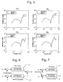
- Fig. 5 shows the frequency-dependent gains of the acceleration measured and of the identified model.
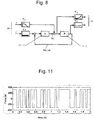
- Fig. 11 shows the force signal for excitation of the actuators 11.
- the excitation takes place with a so-called random binary signal, which is generated by means of a random generator, wherein the Amplitude of the signal fixed, for example, can be set to ⁇ 300 N and the spectrum is broad and evenly distributed.
- the model with the identified parameters forms the basis for the design of an optimal controller for active vibration damping.
- Controller structure and parameters depend on the characteristics of the track to be controlled, in this case the elevator car.
- the elevator car has a static and dynamic behavior which is described by the model.
- Important parameters are: masses and moments of inertia, geometry such as height (s), width (s), depth (s), track mass, etc., spring rates and damping values. If the parameters change, this has an influence on the behavior of the elevator car and thus on the settings of the vibration damping controller.
- a classic PID control proportional, integral and differential control
- three gains have to be set, which can be mastered manually.
- the controller for the present case has well over a hundred parameters, with a manual setting is practically no longer possible. The parameters must therefore be determined automatically. This is only possible with the aid of a model which describes the essential characteristics of the elevator car.
- a dynamic system is time-invariant if the descriptive parameters remain constant.
- a linear controller is time-invariant if system matrices A, B, C and D do not change. Controllers implemented on a digital computer are always time-discrete. That is, they make the inputs, calculations and outputs at fixed intervals.
- Fig. 8 shows the signal flow diagram of the H ⁇ -Entschsvons closed loop.
- the main advantage of the H ⁇ design process is that it can be automated.
- the H ⁇ is.
- Fig. 8 is a scheme to design the controller using the H ⁇ - method.
- w is the vector signal at the input and is composed of v and r.
- T consists of controller, control section and weighting functions.
- P6 or a6 constitute the closed-loop feedback, the position controller or the accelerometer separately designed.
- F6 is the output or the control signal of the controller.
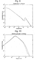
- Fig. 9 shows the course of the singular values of a position controller in the y-direction. This one has predominantly an integrating behavior.
- Fig. 10 shows the course of the singular values of an acceleration controller in the y-direction. This has a bandpass characteristic.
- Singular values are a measure of the overall gain of a matrix.
- An n x n matrix has n singular values.
Landscapes
- Cage And Drive Apparatuses For Elevators (AREA)
- Lift-Guide Devices, And Elevator Ropes And Cables (AREA)
- Elevator Control (AREA)
Claims (9)
- Procédé pour développer un régulateur pour l'amortissement des vibrations contre une cabine d'ascenseur (1), l'ébauche de régulateur se basant sur un modèle de la cabine d'ascenseur (1), un modèle global de la cabine d'ascenseur (1) comprenant des paramètres de modèle plus ou moins bien connus ou évalués étant utilisé, les paramètres pour la cabine d'ascenseur utilisée étant identifiés par comparaison des fonctions de transmission ou des couloirs de fréquences du modèle avec les fonctions de transmission mesurées ou avec les couloirs de fréquences mesurés et les paramètres de modèle étant modifiés pour coïncider le plus possible avec les couloirs de fréquences mesurés, le modèle comportant les paramètres identifiés servant de base au développement d'un régulateur optimal pour l'amortissement des vibrations actif et le système antivibrations actif de la cabine d'ascenseur (1) étant prévu lui-même comme dispositif de mesure pour les fonctions de transmission ou couloirs de fréquences à mesurer, la cabine d'ascenseur (1) étant activée par le biais d'actionneurs (11) et les réponses étant mesurées à l'aide de capteurs d'accélération (13) ou de capteurs de position (12).
- Procédé selon la revendication 1, caractérisé en ce que les paramètres de modèle sont modifiés à l'aide d'un algorithme d'optimisation jusqu'à ce que le minimum de la somme (e) de tous les écarts des couloirs de fréquences du modèle par rapport aux couloirs de fréquences mesurés soit trouvé.
- Procédé selon la revendication 2, caractérisé en ce que les écarts entre les couloirs de fréquences du modèle et les couloirs de fréquences mesurés sont pondérés lors du calcul de la somme (e) avec une valeur w(ω) dépendant de la fréquence.
- Procédé selon l'une quelconque des revendications précédentes, caractérisé en ce que le régulateur (17) est développé à l'aide du procédé H∞.
- Procédé selon la revendication 4, caractérisé en ce que le régulateur (17) comporte un régulateur de position (15) excitant les actionneurs (11) en fonction de la position de la cabine d'ascenseur (1), les éléments de guidage (7) prenant une position prédéfinie, et en ce que le régulateur (17) comporte un régulateur d'accélération (16) excitant les actionneurs (11) en fonction de l'accélération de la cabine d'ascenseur (1), les vibrations survenant contre la cabine d'ascenseur (1) étant jugulées.
- Procédé selon la revendication 5, caractérisé en ce que le régulateur de position (15) et le régulateur d'accélération (16) sont connectés en parallèle, les signaux de réglage du régulateur de position (15) et du régulateur d'accélération (16) étant additionnés et amenés aux actionneurs (11) sous la forme d'un signal de somme.
- Procédé selon la revendication 5, caractérisé en ce que le régulateur de position (15) et le régulateur d'accélération (16) sont connectés en série, le signal de réglage du régulateur de position (15) étant amené au régulateur d'accélération (16) sous la forme d'un signal d'entrée.
- Procédé selon l'une quelconque des revendications 5 à 7, caractérisé en ce que le régulateur de position (15) et le régulateur d'accélération (16) sont pour l'essentiel actifs dans différentes plages de fréquences.
- Procédé selon l'une quelconque des revendications précédentes, caractérisé en ce que le modèle de système à plusieurs corps (MKS), pour une cabine d'ascenseur élastique, comprend au moins deux corps décrivant le corps de cabine (2) ainsi que le châssis de cabine (3) ou, pour une cabine d'ascenseur (1) rigide, un corps de cabine (2) et un châssis de cabine (3) formant ensemble un corps.
Priority Applications (1)
| Application Number | Priority Date | Filing Date | Title |
|---|---|---|---|
| EP20050001167 EP1574469B1 (fr) | 2004-02-02 | 2005-01-21 | Méthode pour développer le régulateur d'un système antichoc de cabine d'ascenseur |
Applications Claiming Priority (3)
| Application Number | Priority Date | Filing Date | Title |
|---|---|---|---|
| EP04405064 | 2004-02-02 | ||
| EP04405064 | 2004-02-02 | ||
| EP20050001167 EP1574469B1 (fr) | 2004-02-02 | 2005-01-21 | Méthode pour développer le régulateur d'un système antichoc de cabine d'ascenseur |
Publications (2)
| Publication Number | Publication Date |
|---|---|
| EP1574469A1 EP1574469A1 (fr) | 2005-09-14 |
| EP1574469B1 true EP1574469B1 (fr) | 2014-03-12 |
Family
ID=34828590
Family Applications (1)
| Application Number | Title | Priority Date | Filing Date |
|---|---|---|---|
| EP20050001167 Expired - Lifetime EP1574469B1 (fr) | 2004-02-02 | 2005-01-21 | Méthode pour développer le régulateur d'un système antichoc de cabine d'ascenseur |
Country Status (1)
| Country | Link |
|---|---|
| EP (1) | EP1574469B1 (fr) |
Families Citing this family (2)
| Publication number | Priority date | Publication date | Assignee | Title |
|---|---|---|---|---|
| US9182753B2 (en) * | 2012-05-10 | 2015-11-10 | Mitsubishi Electric Research Laboratories, Inc. | Model-based learning control |
| JP6407445B2 (ja) * | 2015-08-27 | 2018-10-17 | 三菱電機株式会社 | エレベータ振動低減装置の異常検出装置、エレベータおよびエレベータ振動低減装置の異常検出方法 |
Family Cites Families (1)
| Publication number | Priority date | Publication date | Assignee | Title |
|---|---|---|---|---|
| US5321217A (en) * | 1990-07-18 | 1994-06-14 | Otis Elevator Company | Apparatus and method for controlling an elevator horizontal suspension |
-
2005
- 2005-01-21 EP EP20050001167 patent/EP1574469B1/fr not_active Expired - Lifetime
Also Published As
| Publication number | Publication date |
|---|---|
| EP1574469A1 (fr) | 2005-09-14 |
Similar Documents
| Publication | Publication Date | Title |
|---|---|---|
| EP3137872B1 (fr) | Banc d'essai à rouleaux et procédé d'exploitation pour un banc d'essai à rouleaux | |
| DE69517221T2 (de) | Vorrichtung und Verfahren zum Regeln der Dämpfungscharakteristiken von Fahrzeugstossdämpfern | |
| DE4115481C2 (de) | System zur Erhöhung des Fahrkomforts und der Fahrsicherheit | |
| EP3092471B1 (fr) | Procédé et dispositif de régulation d'un banc d'essai de chaîne cinématique | |
| DE112014001217B4 (de) | Verfahren und System zur Regelung einer Menge von semiaktiven Aktoren, die in einem Aufzug angeordnet sind | |
| DE4040376C2 (de) | Radaufhängungs-Regeleinrichtung | |
| EP0696729B1 (fr) | Procédé et dispositif de simulation de masse dans un banc d'essai fixe | |
| AT515712B1 (de) | Verfahren zur Nachbildung des Fahrzeugverhaltens und Fahrzeugprüfstand | |
| DE102008041745B4 (de) | Verfahren und Vorrichtung zum Prüfen wenigstens eines Schwingungsdämpfers eines Kraftfahrzeugs im eingebauten Zustand | |
| DE102007051218A1 (de) | Verfahren und Regelungssystem/Regelungskomponente zur Bestimmung von dynamischen Nick-, Wank- und/oder Hubachsen | |
| DE112015003800T5 (de) | Signalverarbeitungsvorrichtung, Signalverarbeitungsverfahren, Vorrichtung zur Steuerung einer Federung und Verfahren zur Steuerung einer Federung | |
| DE4015221A1 (de) | Vibrationssteuervorrichtung fuer eine fahrzeugkarosserie | |
| EP1574469B1 (fr) | Méthode pour développer le régulateur d'un système antichoc de cabine d'ascenseur | |
| AT522480B1 (de) | Verfahren zum Betreiben einer Bearbeitungsanlage | |
| DE69211040T2 (de) | Aufzugsschienenquerschnittbewertung und Aufzugssteuerungsverfahren | |
| DE4303039C2 (de) | Semiaktive Aufhängungssteuervorrichtung nach dem Skyhook-Prinzip | |
| DE102016123420B4 (de) | Verfahren und Steuerungseinrichtung zur Einstellung der Dämpfkraft eines Stoßdämpfers | |
| DE69108122T2 (de) | Dämpfungsvorrichtungen. | |
| DE102017106559B4 (de) | Auslegung oder Durchführung einer Bewegungsaufgabe einer bewegten Masse in einer mechanischen Anlage entlang zumindest einer Bewegungsachse | |
| AT519997B1 (de) | Ermittlung einer Fahrzeuglängsbeschleunigung am Prüfstand | |
| DE112013006705B4 (de) | Verfahren und System zum Steuern eines Satzes semi-aktiver Betätigungselemente, die in einem Aufzugsystem installiert sind | |
| EP3098654A1 (fr) | Procédé de réglage d'un système actif d'isolation des vibrations | |
| DE102020215163B4 (de) | Verfahren zum Überwachen der Funktionsfähigkeit eines Stoßdämpfers eines Kraftfahrzeugs | |
| DE102009003919A1 (de) | Verfahren zur Verhinderung der Schwingungsanregung eines durch einen Antrieb bewegbaren Maschinenelements | |
| EP1547956B1 (fr) | Dispositif et méthode pour la réduction des vibrations d'un cage d'ascenseur |
Legal Events
| Date | Code | Title | Description |
|---|---|---|---|
| PUAI | Public reference made under article 153(3) epc to a published international application that has entered the european phase |
Free format text: ORIGINAL CODE: 0009012 |
|
| AK | Designated contracting states |
Kind code of ref document: A1 Designated state(s): AT BE BG CH CY CZ DE DK EE ES FI FR GB GR HU IE IS IT LI LT LU MC NL PL PT RO SE SI SK TR |
|
| AX | Request for extension of the european patent |
Extension state: AL BA HR LV MK YU |
|
| 17P | Request for examination filed |
Effective date: 20060227 |
|
| AKX | Designation fees paid |
Designated state(s): AT CH DE FR GB LI |
|
| REG | Reference to a national code |
Ref country code: HK Ref legal event code: DE Ref document number: 1082720 Country of ref document: HK |
|
| 17Q | First examination report despatched |
Effective date: 20130701 |
|
| GRAP | Despatch of communication of intention to grant a patent |
Free format text: ORIGINAL CODE: EPIDOSNIGR1 |
|
| INTG | Intention to grant announced |
Effective date: 20131128 |
|
| GRAS | Grant fee paid |
Free format text: ORIGINAL CODE: EPIDOSNIGR3 |
|
| GRAA | (expected) grant |
Free format text: ORIGINAL CODE: 0009210 |
|
| AK | Designated contracting states |
Kind code of ref document: B1 Designated state(s): AT CH DE FR GB LI |
|
| REG | Reference to a national code |
Ref country code: GB Ref legal event code: FG4D Free format text: NOT ENGLISH |
|
| REG | Reference to a national code |
Ref country code: CH Ref legal event code: EP |
|
| REG | Reference to a national code |
Ref country code: AT Ref legal event code: REF Ref document number: 656149 Country of ref document: AT Kind code of ref document: T Effective date: 20140315 |
|
| REG | Reference to a national code |
Ref country code: DE Ref legal event code: R096 Ref document number: 502005014230 Country of ref document: DE Effective date: 20140417 |
|
| REG | Reference to a national code |
Ref country code: HK Ref legal event code: GR Ref document number: 1082720 Country of ref document: HK |
|
| REG | Reference to a national code |
Ref country code: DE Ref legal event code: R097 Ref document number: 502005014230 Country of ref document: DE |
|
| PLBE | No opposition filed within time limit |
Free format text: ORIGINAL CODE: 0009261 |
|
| STAA | Information on the status of an ep patent application or granted ep patent |
Free format text: STATUS: NO OPPOSITION FILED WITHIN TIME LIMIT |
|
| 26N | No opposition filed |
Effective date: 20141215 |
|
| REG | Reference to a national code |
Ref country code: DE Ref legal event code: R097 Ref document number: 502005014230 Country of ref document: DE Effective date: 20141215 |
|
| REG | Reference to a national code |
Ref country code: FR Ref legal event code: PLFP Year of fee payment: 12 |
|
| REG | Reference to a national code |
Ref country code: AT Ref legal event code: MM01 Ref document number: 656149 Country of ref document: AT Kind code of ref document: T Effective date: 20150121 |
|
| PGFP | Annual fee paid to national office [announced via postgrant information from national office to epo] |
Ref country code: CH Payment date: 20160125 Year of fee payment: 12 |
|
| PG25 | Lapsed in a contracting state [announced via postgrant information from national office to epo] |
Ref country code: AT Free format text: LAPSE BECAUSE OF NON-PAYMENT OF DUE FEES Effective date: 20150121 |
|
| REG | Reference to a national code |
Ref country code: FR Ref legal event code: PLFP Year of fee payment: 13 |
|
| REG | Reference to a national code |
Ref country code: CH Ref legal event code: PL |
|
| PG25 | Lapsed in a contracting state [announced via postgrant information from national office to epo] |
Ref country code: LI Free format text: LAPSE BECAUSE OF NON-PAYMENT OF DUE FEES Effective date: 20170131 Ref country code: CH Free format text: LAPSE BECAUSE OF NON-PAYMENT OF DUE FEES Effective date: 20170131 |
|
| REG | Reference to a national code |
Ref country code: FR Ref legal event code: PLFP Year of fee payment: 14 |
|
| PGFP | Annual fee paid to national office [announced via postgrant information from national office to epo] |
Ref country code: GB Payment date: 20190121 Year of fee payment: 15 Ref country code: FR Payment date: 20190123 Year of fee payment: 15 Ref country code: DE Payment date: 20190123 Year of fee payment: 15 |
|
| REG | Reference to a national code |
Ref country code: DE Ref legal event code: R119 Ref document number: 502005014230 Country of ref document: DE |
|
| GBPC | Gb: european patent ceased through non-payment of renewal fee |
Effective date: 20200121 |
|
| PG25 | Lapsed in a contracting state [announced via postgrant information from national office to epo] |
Ref country code: FR Free format text: LAPSE BECAUSE OF NON-PAYMENT OF DUE FEES Effective date: 20200131 Ref country code: DE Free format text: LAPSE BECAUSE OF NON-PAYMENT OF DUE FEES Effective date: 20200801 Ref country code: GB Free format text: LAPSE BECAUSE OF NON-PAYMENT OF DUE FEES Effective date: 20200121 |