EP1574469A1 - Méthode pour développer le régulateur d'un système antichoc de cabine d'ascenseur - Google Patents
Méthode pour développer le régulateur d'un système antichoc de cabine d'ascenseur Download PDFInfo
- Publication number
- EP1574469A1 EP1574469A1 EP05001167A EP05001167A EP1574469A1 EP 1574469 A1 EP1574469 A1 EP 1574469A1 EP 05001167 A EP05001167 A EP 05001167A EP 05001167 A EP05001167 A EP 05001167A EP 1574469 A1 EP1574469 A1 EP 1574469A1
- Authority
- EP
- European Patent Office
- Prior art keywords
- elevator car
- controller
- model
- acceleration
- parameters
- Prior art date
- Legal status (The legal status is an assumption and is not a legal conclusion. Google has not performed a legal analysis and makes no representation as to the accuracy of the status listed.)
- Granted
Links
- 238000013461 design Methods 0.000 title claims abstract description 18
- 238000000034 method Methods 0.000 title claims description 25
- 230000035939 shock Effects 0.000 title 1
- 230000004044 response Effects 0.000 claims abstract description 28
- 238000013016 damping Methods 0.000 claims abstract description 15
- 230000001133 acceleration Effects 0.000 claims description 38
- 230000005540 biological transmission Effects 0.000 claims description 6
- 238000005457 optimization Methods 0.000 claims description 6
- 230000001419 dependent effect Effects 0.000 claims description 5
- 238000004364 calculation method Methods 0.000 claims description 2
- 230000008569 process Effects 0.000 claims description 2
- 238000012546 transfer Methods 0.000 abstract description 9
- 239000011159 matrix material Substances 0.000 description 9
- 238000005259 measurement Methods 0.000 description 6
- 230000000694 effects Effects 0.000 description 4
- 238000001228 spectrum Methods 0.000 description 4
- 230000008878 coupling Effects 0.000 description 3
- 238000010168 coupling process Methods 0.000 description 3
- 238000005859 coupling reaction Methods 0.000 description 3
- 230000005284 excitation Effects 0.000 description 3
- 230000008859 change Effects 0.000 description 2
- 238000010586 diagram Methods 0.000 description 2
- 230000033001 locomotion Effects 0.000 description 2
- 230000001105 regulatory effect Effects 0.000 description 2
- 238000005096 rolling process Methods 0.000 description 2
- 230000003068 static effect Effects 0.000 description 2
- 230000008901 benefit Effects 0.000 description 1
- 230000006835 compression Effects 0.000 description 1
- 238000007906 compression Methods 0.000 description 1
- 238000010276 construction Methods 0.000 description 1
- 230000007423 decrease Effects 0.000 description 1
- 238000012938 design process Methods 0.000 description 1
- 238000011161 development Methods 0.000 description 1
- 230000018109 developmental process Effects 0.000 description 1
- 230000004069 differentiation Effects 0.000 description 1
- 229920001971 elastomer Polymers 0.000 description 1
- 239000000806 elastomer Substances 0.000 description 1
- 230000005484 gravity Effects 0.000 description 1
- 238000009413 insulation Methods 0.000 description 1
- 230000009022 nonlinear effect Effects 0.000 description 1
- 230000036316 preload Effects 0.000 description 1
- 230000009467 reduction Effects 0.000 description 1
- 230000002787 reinforcement Effects 0.000 description 1
- 238000011160 research Methods 0.000 description 1
- 238000012360 testing method Methods 0.000 description 1
- 230000009466 transformation Effects 0.000 description 1
Images


Classifications
-
- B—PERFORMING OPERATIONS; TRANSPORTING
- B66—HOISTING; LIFTING; HAULING
- B66B—ELEVATORS; ESCALATORS OR MOVING WALKWAYS
- B66B7/00—Other common features of elevators
- B66B7/02—Guideways; Guides
- B66B7/04—Riding means, e.g. Shoes, Rollers, between car and guiding means, e.g. rails, ropes
- B66B7/041—Riding means, e.g. Shoes, Rollers, between car and guiding means, e.g. rails, ropes including active attenuation system for shocks, vibrations
-
- B—PERFORMING OPERATIONS; TRANSPORTING
- B66—HOISTING; LIFTING; HAULING
- B66B—ELEVATORS; ESCALATORS OR MOVING WALKWAYS
- B66B7/00—Other common features of elevators
- B66B7/02—Guideways; Guides
- B66B7/04—Riding means, e.g. Shoes, Rollers, between car and guiding means, e.g. rails, ropes
- B66B7/046—Rollers
Definitions
- the invention relates to a method for the design of a Regulator for vibration damping in an elevator car, wherein the regulator design is based on a model of the elevator cabin.
- Patent EP 0 731 051 B1 discloses a device and a method for vibration damping on a Elevator car became known. Transverse to the direction of travel occurring vibrations or accelerations are through a quick scheme reduced, so they in the Elevator car are no longer noticeable. To capture the Measurements are arranged on the cabin frame inertial sensors. In addition, a slow position controller leads the Elevator cabin with one-sided imbalance to the Guide rails automatically in a central position, wherein Position sensors that supply measured values to position controllers.
- the elevator car is a multi-size controller and another Multi-size controller for maintaining the game to the Guide rollers or the upright position of the elevator car intended.
- the control signals of the two controllers are added and control one actuator per roller guide and per Horizontal direction.
- the controller design is based on a model of the elevator car, which takes into account the essential structural resonances.
- the disadvantage is that the overall model is too complex tends, despite sophisticated methods for reducing the number Poles. As a result, the model-based controller becomes also complex.
- the invention aims to remedy this situation.
- the invention how it is characterized in claim 1, solves the problem, the Disadvantages of the known method to avoid and a simple procedure for the design of a controller propose.
- a Overall model of the elevator car with known structure specified It is a so-called Multibody (MBS) model, which has several rigid bodies includes.
- MKS Multibody
- the MKS model describes the essential elastic Structure of the elevator car with the guide rollers and the Actuators and the power coupling with the guide rails.
- the model parameters are more or less well known or there are estimates, the parameters for the used to identify or determine the elevator car used are.
- the transfer functions or Frequency responses of the model with the measured Transmission functions or frequency responses compared.
- Help of an algorithm to optimize functions with several variables are the estimated model parameters changed in order to achieve the greatest possible agreement.
- the active vibration damping system of the elevator car itself is usable.
- the actuators is the elevator car stimulated and with the acceleration sensors or with the Position sensors are measured the answers.
- This model-based design method of the controller ensures the best possible active vibration damping for the individual elevator cabins with very different ones Parameters.
- a robust multi-size controller is designed for reduction acceleration and a position regulator for Maintaining the game on the leadership roles.
- the acceleration controller has the behavior of a Bandpass filters and the best effect in a medium Frequency range from about 1 Hz to 4 Hz. Below and above this frequency band is the gain and thus reduces the effectiveness of the acceleration regulator.
- the position controller causes the elevator car an average of the rail profiles follows while the Accelerator causes a rectilinear motion. This conflict of objectives is resolved by turning the two knobs in different frequency ranges are effective.
- the Gain of the positioner is at low frequencies big and then decreases. That is, he has the property a low-pass filter. Conversely, the Acceleration controller at low frequencies a small Gain.
- the first structural resonance can For example, at 12 Hz, this value is strong depends on the construction of the elevator car and clearly can be lower. Above the first structural resonance can the controller no longer accelerates the car body to reduce. There is even a risk that Structural resonances are stimulated, or that instability can occur. With knowledge of the dynamic system model the controller, the controller can be designed so that this can be avoided.
- the MKS model must have the essential characteristics of Regulate elevator car regarding ride comfort. Since at the Identification of parameters only with linear models All nonlinear effects must be able to be worked be ignored.
- the first natural frequencies of the elastic elevator cabins are so deep that they are with the so-called rigid body natural frequencies of the entire cabin can overlap.
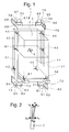
- Fig. 1 are for modeling the elastic Elevator car 1 at least two rigid bodies required namely cabin body 2 and cabin frame 3.
- Cabin body 2 and cabin frame 3 are by means of elastomer springs 4.1 to 4.6, the so-called cabin insulation 4 connected. This is reduced the transmission of structure-borne noise from the frame to the Cab body.
- cabin body and cabin frame As shown in Fig. 1 are for modeling the elastic Elevator car 1 at least two rigid bodies required namely cabin body 2 and cabin frame 3.
- Cabin body 2 and cabin frame 3 are by means of elastomer springs 4.1 to 4.6, the so-called cabin insulation 4 connected. This is reduced
- the transverse rigidity of cabin body 2 and cab frame 3 is much lower than the stiffness in Vertical direction. This can be done with the division in each at least two rigid bodies, namely cabin body 2.1 and 2.2 and cabin frames 3.1 and 3.2 are modeled.
- the at least two sub-bodies are horizontal by springs 5, 6.1 and 6.2 coupled and can be connected vertically as rigid to be viewed as.
- the guide rollers 7.1 to 7.8 with the proportionate masses of Levers and actuators can work with at least 8 rigid bodies modeled or neglected. This is dependent from the associated natural frequencies of the guide rollers and considered from the upper limit of the frequency range of becomes. Since the natural frequency of the actuator-roller system in Regulated condition can lead to instability, the Modeling with rigid bodies is preferred. These are only perpendicular to the footprint on the rail opposite the Sliding frame and with the roller guide springs 8.1 bis 8.8 coupled. In the other directions they are rigid with connected to the frame.
- the leadership behavior or the Force coupling between guide rollers and guide rails important. To model are essentially only the two horizontal force components necessary. The vertical one Force component that results from the rolling resistance can be ignored. The normal force results from the elastic compression of the roller covering 9.1 to 9.8. The Axial or lateral force results from the angle between the Straight lines perpendicular to the roll axis and parallel to the rail and the actual direction of movement of the Roll center.
- v K and F RN can be considered constant if the preload force is significantly greater than the dynamic part of the normal force. This means that the roller force in the axial direction is proportional and opposite to the speed in the axial direction and inversely proportional to the driving speed of the elevator car.
- Transverse vibrations of the cabin are thus due to the roles steamed as from a viscous damper, with the effect becomes smaller with increasing travel speed.
- the guide rollers 7 with a order an axle 10 'rotatable lever 10 with the cab frame 3 connected, wherein the roller guide spring 8 a force generated between the lever and cab frame.
- An actuator 11 generates a force parallel to the roller guide spring acts.
- a position sensor 12 measures the position of the lever 10 and the guide roller 7.
- An acceleration sensor 13th measures the acceleration of the cabin frame 3 perpendicular to Footprint of the roller lining 9 on the guide rail 14.
- the reference number of the respective element applies as in Fig. 1 shown (for example, on the elevator car 1 below right: 7.1.8.1.9.1,10.1,11.1,12.1,13.1).
- the Number of required acceleration sensors 13 corresponds the number of controlled axles, with at least three and at most six acceleration sensors are provided.
- an i is a triple of signals Fn i , Pn i , i for actuator force, position and acceleration.
- the index i is the consecutive numbering in the respective axis system and n stands for number of axes of the system.
- one or more actuators are actuated with a force signal as shown in FIG. 11, and the elevator car 1 is excited to vibrations transverse to the direction of travel in such a way that clearly measurable signals are produced in the position sensors 12 and in the acceleration sensors 13. So that the correlation of the measurements with the force signals can be reliably determined, usually only one actuator or actuator pair is driven. As shown in Table 1, at least as many test drives are necessary as active axles are provided.
- the frequency spectrum of the force signals and the measured position signals and acceleration signals are determined by Fourier transformation.
- the transfer functions in the frequency domain or frequency responses G i , j ( ⁇ ) with the angular frequency ⁇ as an argument are determined by dividing the spectra of the measurements by the associated spectrum of the force signal.
- i the index of the measurement
- j the index of the force.
- G P i . j ( ⁇ ) P i ( ⁇ ) F j ( ⁇ )
- G a i . j ( ⁇ ) a i ( ⁇ ) F j ( ⁇ )
- G P i , j ( ⁇ ) are the individual frequency responses from force to position and G a i , j ( ⁇ ) are the individual frequency responses from force to acceleration.
- the matrix G P ( ⁇ ) contains all frequency responses force to position and matrix G a ( ⁇ ) all frequency responses force to acceleration.
- Matrix G ( ⁇ ) arises from the vertical composition of G P ( ⁇ ) and G a ( ⁇ ).
- the vector x ⁇ contains the derivatives of x after the time.
- y is a vector containing the measured quantities, ie positions and accelerations.
- the vector u contains the inputs (actuator forces) of the system.
- A, B, C and D are matrices which together form the so-called Jacobian matrix by which a linear system is completely described.
- G ⁇ ( ⁇ ) is a matrix with the same number of rows as measurements in vector y and the same number of columns as inputs in vector u and contains all frequency responses of the MKS model of the cabin.
- a Jacobian matrix contains all partial derivatives of a System of equations.
- Coupled differential equations of 1st order are the constant coefficients of the A, B, C and D matrices.
- the model contains a number of well known parameters such as dimensions and mass and a number of poorly known parameters such as spring rates and damping constants. It is important to identify these poorly known parameters. The identification is performed by comparing the frequency responses of the model with the measured frequency responses. With an optimization algorithm, the poorly known model parameters are changed until the minimum of the sum e of all deviations of the frequency responses of the model from the measured frequency responses is found.
- w ( ⁇ ) is a frequency-dependent weighting. It ensures that only important parts of the measured frequency responses are modeled in the model.
- An optimization algorithm can briefly rewrite as follows Given is a function with multiple variables. We are looking for a minimum or maximum of this function. One Optimization algorithm searches for these extremes. There are many different algorithms, e.g. the method of the fastest Descent seeks the greatest gradient with the help of partial derivatives and finds local minima quickly, can but others overlook it. Optimization is in many Subject areas applied mathematics and an important area scientific research.
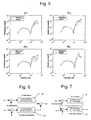
- Fig. 5 shows the frequency-dependent gains of the acceleration measured and of the identified model.
- means magnitude or amplitude of the transfer function or the frequency response force to acceleration with output acceleration of axis 1 and with input force of axis 1.
- the 11 shows the force signal for excitation of the actuators 11.
- the excitation takes place with a so-called Random Binary Signal generated by a random generator, the Amplitude of the signal fixed, for example to ⁇ 300 N. can be adjusted and the spectrum wide and is evenly distributed.
- the model with the identified parameters forms the Basis for the design of an optimal controller for active Vibration damping. Controller structure and parameters are depending on the characteristics of the track to be regulated, in this case of the elevator car.
- the elevator car has a static and dynamic behavior caused by the Model is described. Important parameters are: masses and Moments of inertia, geometry such as height (s), Width (s), depth (s), track gauge, etc., spring rates and Attenuation values. If the parameters change, so does that Influence on the behavior of the elevator car and thus on the settings of the vibration damping controller.
- at a classic PID controller proportional, integral and Differential control
- the regulator for the present case has well over a hundred parameters, with a Manual adjustment is practically impossible. The Parameters must therefore be determined automatically. This is only with the help of a model that is the essential Describes characteristics of the elevator car, possible.
- a dynamic system is time-invariant when the descriptive parameters remain constant.
- a linear one Controller is time-invariant when system matrices A, B, C and D not change. Controller on a digital computer are realized are always time-discrete. That means, you make the inputs, calculations and outputs in fixed Intervals.
- Fig. 8 shows the signal flow scheme of the closed-loop H ⁇ drafting process.
- the main advantage of the H ⁇ design process is that it can be automated. Standard minimizes the system to be controlled with a closed loop -
- the H ⁇ is.
- the H ⁇ - norm of a matrix A with m ⁇ n elements is given by:
- Fig. 8 is a diagram for designing the regulator with the H ⁇ method.
- w is the vector signal at the input and is composed of v and r.
- T consists of controller, control section and weighting functions.
- P6 or a6 constitute the closed-loop feedback, the position controller or the accelerometer separately designed.
- F6 is the output or the control signal of the controller.
- Singular values are a measure of the overall gain of a Matrix.
- An n x n matrix has n singular values.
Landscapes
- Cage And Drive Apparatuses For Elevators (AREA)
- Lift-Guide Devices, And Elevator Ropes And Cables (AREA)
- Elevator Control (AREA)
Priority Applications (1)
| Application Number | Priority Date | Filing Date | Title |
|---|---|---|---|
| EP20050001167 EP1574469B1 (fr) | 2004-02-02 | 2005-01-21 | Méthode pour développer le régulateur d'un système antichoc de cabine d'ascenseur |
Applications Claiming Priority (3)
| Application Number | Priority Date | Filing Date | Title |
|---|---|---|---|
| EP04405064 | 2004-02-02 | ||
| EP04405064 | 2004-02-02 | ||
| EP20050001167 EP1574469B1 (fr) | 2004-02-02 | 2005-01-21 | Méthode pour développer le régulateur d'un système antichoc de cabine d'ascenseur |
Publications (2)
| Publication Number | Publication Date |
|---|---|
| EP1574469A1 true EP1574469A1 (fr) | 2005-09-14 |
| EP1574469B1 EP1574469B1 (fr) | 2014-03-12 |
Family
ID=34828590
Family Applications (1)
| Application Number | Title | Priority Date | Filing Date |
|---|---|---|---|
| EP20050001167 Expired - Lifetime EP1574469B1 (fr) | 2004-02-02 | 2005-01-21 | Méthode pour développer le régulateur d'un système antichoc de cabine d'ascenseur |
Country Status (1)
| Country | Link |
|---|---|
| EP (1) | EP1574469B1 (fr) |
Cited By (2)
| Publication number | Priority date | Publication date | Assignee | Title |
|---|---|---|---|---|
| WO2013168749A1 (fr) * | 2012-05-10 | 2013-11-14 | Mitsubishi Electric Corporation | Système de commande et procede de commande du fonctionnement d'un système |
| CN107922144A (zh) * | 2015-08-27 | 2018-04-17 | 三菱电机株式会社 | 电梯减振装置的异常检测装置、电梯及电梯减振装置的异常检测方法 |
Citations (1)
| Publication number | Priority date | Publication date | Assignee | Title |
|---|---|---|---|---|
| US5321217A (en) * | 1990-07-18 | 1994-06-14 | Otis Elevator Company | Apparatus and method for controlling an elevator horizontal suspension |
-
2005
- 2005-01-21 EP EP20050001167 patent/EP1574469B1/fr not_active Expired - Lifetime
Patent Citations (1)
| Publication number | Priority date | Publication date | Assignee | Title |
|---|---|---|---|---|
| US5321217A (en) * | 1990-07-18 | 1994-06-14 | Otis Elevator Company | Apparatus and method for controlling an elevator horizontal suspension |
Non-Patent Citations (1)
| Title |
|---|
| MARRA M A ET AL: "VIBRATION CONTROL FOR MACHINING USING H TECHNIQUES", PROCEEDINGS OF SOUTHEASTCON. RALEIGH, MAR. 26 - 29, 1995, NEW YORK, IEEE, US, 26 March 1995 (1995-03-26), pages 436 - 442, XP000538678, ISBN: 0-7803-2643-1 * |
Cited By (3)
| Publication number | Priority date | Publication date | Assignee | Title |
|---|---|---|---|---|
| WO2013168749A1 (fr) * | 2012-05-10 | 2013-11-14 | Mitsubishi Electric Corporation | Système de commande et procede de commande du fonctionnement d'un système |
| CN107922144A (zh) * | 2015-08-27 | 2018-04-17 | 三菱电机株式会社 | 电梯减振装置的异常检测装置、电梯及电梯减振装置的异常检测方法 |
| CN107922144B (zh) * | 2015-08-27 | 2020-10-27 | 三菱电机株式会社 | 电梯减振装置的异常检测装置及方法、电梯 |
Also Published As
| Publication number | Publication date |
|---|---|
| EP1574469B1 (fr) | 2014-03-12 |
Similar Documents
| Publication | Publication Date | Title |
|---|---|---|
| EP3137872B1 (fr) | Banc d'essai à rouleaux et procédé d'exploitation pour un banc d'essai à rouleaux | |
| DE69517221T2 (de) | Vorrichtung und Verfahren zum Regeln der Dämpfungscharakteristiken von Fahrzeugstossdämpfern | |
| DE112010005840B4 (de) | Fahrzeugregelungsvorrichtung | |
| DE4115481C2 (de) | System zur Erhöhung des Fahrkomforts und der Fahrsicherheit | |
| EP3092471B1 (fr) | Procédé et dispositif de régulation d'un banc d'essai de chaîne cinématique | |
| DE112014001217B4 (de) | Verfahren und System zur Regelung einer Menge von semiaktiven Aktoren, die in einem Aufzug angeordnet sind | |
| DE4040376C2 (de) | Radaufhängungs-Regeleinrichtung | |
| DE69710811T2 (de) | Rechengerät für die relative Geschwindigkeit zwischen gefederter und nicht gefederter Struktur eines Fahrzeuges | |
| DE112007003699B4 (de) | Türsteuervorrichtung für einen Aufzug | |
| DE102010003205A1 (de) | Verfahren zur Bestimmung der vertikalen Beschleunigung, der longitudinalen Winkelbeschleunigung und der transversalen Winkelbeschleunigung eines Körpers, insbesondere eines Kraftfahrzeugs | |
| EP0696729B1 (fr) | Procédé et dispositif de simulation de masse dans un banc d'essai fixe | |
| AT515712B1 (de) | Verfahren zur Nachbildung des Fahrzeugverhaltens und Fahrzeugprüfstand | |
| DE112015003800T5 (de) | Signalverarbeitungsvorrichtung, Signalverarbeitungsverfahren, Vorrichtung zur Steuerung einer Federung und Verfahren zur Steuerung einer Federung | |
| DE102007051218A1 (de) | Verfahren und Regelungssystem/Regelungskomponente zur Bestimmung von dynamischen Nick-, Wank- und/oder Hubachsen | |
| DE112015003809T5 (de) | Vorrichtung und Verfahren zur Steuerung einer Federung und Programm | |
| DE4015221A1 (de) | Vibrationssteuervorrichtung fuer eine fahrzeugkarosserie | |
| DE102019118904A1 (de) | Dämpfungsvorrichtung eines Fahrzeugs und zugeordnetes Verfahren | |
| AT522480B1 (de) | Verfahren zum Betreiben einer Bearbeitungsanlage | |
| EP1574469B1 (fr) | Méthode pour développer le régulateur d'un système antichoc de cabine d'ascenseur | |
| DE4303039C2 (de) | Semiaktive Aufhängungssteuervorrichtung nach dem Skyhook-Prinzip | |
| DE69211040T2 (de) | Aufzugsschienenquerschnittbewertung und Aufzugssteuerungsverfahren | |
| DE69108122T2 (de) | Dämpfungsvorrichtungen. | |
| DE102016123420A1 (de) | Verfahren und Steuerungseinrichtung zur Einstellung der Dämpfkraft eines Stoßdämpfers | |
| DE102017106559B4 (de) | Auslegung oder Durchführung einer Bewegungsaufgabe einer bewegten Masse in einer mechanischen Anlage entlang zumindest einer Bewegungsachse | |
| AT519997B1 (de) | Ermittlung einer Fahrzeuglängsbeschleunigung am Prüfstand |
Legal Events
| Date | Code | Title | Description |
|---|---|---|---|
| PUAI | Public reference made under article 153(3) epc to a published international application that has entered the european phase |
Free format text: ORIGINAL CODE: 0009012 |
|
| AK | Designated contracting states |
Kind code of ref document: A1 Designated state(s): AT BE BG CH CY CZ DE DK EE ES FI FR GB GR HU IE IS IT LI LT LU MC NL PL PT RO SE SI SK TR |
|
| AX | Request for extension of the european patent |
Extension state: AL BA HR LV MK YU |
|
| 17P | Request for examination filed |
Effective date: 20060227 |
|
| AKX | Designation fees paid |
Designated state(s): AT CH DE FR GB LI |
|
| REG | Reference to a national code |
Ref country code: HK Ref legal event code: DE Ref document number: 1082720 Country of ref document: HK |
|
| 17Q | First examination report despatched |
Effective date: 20130701 |
|
| GRAP | Despatch of communication of intention to grant a patent |
Free format text: ORIGINAL CODE: EPIDOSNIGR1 |
|
| INTG | Intention to grant announced |
Effective date: 20131128 |
|
| GRAS | Grant fee paid |
Free format text: ORIGINAL CODE: EPIDOSNIGR3 |
|
| GRAA | (expected) grant |
Free format text: ORIGINAL CODE: 0009210 |
|
| AK | Designated contracting states |
Kind code of ref document: B1 Designated state(s): AT CH DE FR GB LI |
|
| REG | Reference to a national code |
Ref country code: GB Ref legal event code: FG4D Free format text: NOT ENGLISH |
|
| REG | Reference to a national code |
Ref country code: CH Ref legal event code: EP |
|
| REG | Reference to a national code |
Ref country code: AT Ref legal event code: REF Ref document number: 656149 Country of ref document: AT Kind code of ref document: T Effective date: 20140315 |
|
| REG | Reference to a national code |
Ref country code: DE Ref legal event code: R096 Ref document number: 502005014230 Country of ref document: DE Effective date: 20140417 |
|
| REG | Reference to a national code |
Ref country code: HK Ref legal event code: GR Ref document number: 1082720 Country of ref document: HK |
|
| REG | Reference to a national code |
Ref country code: DE Ref legal event code: R097 Ref document number: 502005014230 Country of ref document: DE |
|
| PLBE | No opposition filed within time limit |
Free format text: ORIGINAL CODE: 0009261 |
|
| STAA | Information on the status of an ep patent application or granted ep patent |
Free format text: STATUS: NO OPPOSITION FILED WITHIN TIME LIMIT |
|
| 26N | No opposition filed |
Effective date: 20141215 |
|
| REG | Reference to a national code |
Ref country code: DE Ref legal event code: R097 Ref document number: 502005014230 Country of ref document: DE Effective date: 20141215 |
|
| REG | Reference to a national code |
Ref country code: FR Ref legal event code: PLFP Year of fee payment: 12 |
|
| REG | Reference to a national code |
Ref country code: AT Ref legal event code: MM01 Ref document number: 656149 Country of ref document: AT Kind code of ref document: T Effective date: 20150121 |
|
| PGFP | Annual fee paid to national office [announced via postgrant information from national office to epo] |
Ref country code: CH Payment date: 20160125 Year of fee payment: 12 |
|
| PG25 | Lapsed in a contracting state [announced via postgrant information from national office to epo] |
Ref country code: AT Free format text: LAPSE BECAUSE OF NON-PAYMENT OF DUE FEES Effective date: 20150121 |
|
| REG | Reference to a national code |
Ref country code: FR Ref legal event code: PLFP Year of fee payment: 13 |
|
| REG | Reference to a national code |
Ref country code: CH Ref legal event code: PL |
|
| PG25 | Lapsed in a contracting state [announced via postgrant information from national office to epo] |
Ref country code: LI Free format text: LAPSE BECAUSE OF NON-PAYMENT OF DUE FEES Effective date: 20170131 Ref country code: CH Free format text: LAPSE BECAUSE OF NON-PAYMENT OF DUE FEES Effective date: 20170131 |
|
| REG | Reference to a national code |
Ref country code: FR Ref legal event code: PLFP Year of fee payment: 14 |
|
| PGFP | Annual fee paid to national office [announced via postgrant information from national office to epo] |
Ref country code: GB Payment date: 20190121 Year of fee payment: 15 Ref country code: FR Payment date: 20190123 Year of fee payment: 15 Ref country code: DE Payment date: 20190123 Year of fee payment: 15 |
|
| REG | Reference to a national code |
Ref country code: DE Ref legal event code: R119 Ref document number: 502005014230 Country of ref document: DE |
|
| GBPC | Gb: european patent ceased through non-payment of renewal fee |
Effective date: 20200121 |
|
| PG25 | Lapsed in a contracting state [announced via postgrant information from national office to epo] |
Ref country code: FR Free format text: LAPSE BECAUSE OF NON-PAYMENT OF DUE FEES Effective date: 20200131 Ref country code: DE Free format text: LAPSE BECAUSE OF NON-PAYMENT OF DUE FEES Effective date: 20200801 Ref country code: GB Free format text: LAPSE BECAUSE OF NON-PAYMENT OF DUE FEES Effective date: 20200121 |