EP1574469A1 - Design method for the controller design of an active elevator car shock attenuation system - Google Patents
Design method for the controller design of an active elevator car shock attenuation system Download PDFInfo
- Publication number
- EP1574469A1 EP1574469A1 EP05001167A EP05001167A EP1574469A1 EP 1574469 A1 EP1574469 A1 EP 1574469A1 EP 05001167 A EP05001167 A EP 05001167A EP 05001167 A EP05001167 A EP 05001167A EP 1574469 A1 EP1574469 A1 EP 1574469A1
- Authority
- EP
- European Patent Office
- Prior art keywords
- elevator car
- controller
- model
- acceleration
- parameters
- Prior art date
- Legal status (The legal status is an assumption and is not a legal conclusion. Google has not performed a legal analysis and makes no representation as to the accuracy of the status listed.)
- Granted
Links
- 238000013461 design Methods 0.000 title claims abstract description 18
- 238000000034 method Methods 0.000 title claims description 25
- 230000035939 shock Effects 0.000 title 1
- 230000004044 response Effects 0.000 claims abstract description 28
- 238000013016 damping Methods 0.000 claims abstract description 15
- 230000001133 acceleration Effects 0.000 claims description 38
- 230000005540 biological transmission Effects 0.000 claims description 6
- 238000005457 optimization Methods 0.000 claims description 6
- 230000001419 dependent effect Effects 0.000 claims description 5
- 238000004364 calculation method Methods 0.000 claims description 2
- 230000008569 process Effects 0.000 claims description 2
- 238000012546 transfer Methods 0.000 abstract description 9
- 239000011159 matrix material Substances 0.000 description 9
- 238000005259 measurement Methods 0.000 description 6
- 230000000694 effects Effects 0.000 description 4
- 238000001228 spectrum Methods 0.000 description 4
- 230000008878 coupling Effects 0.000 description 3
- 238000010168 coupling process Methods 0.000 description 3
- 238000005859 coupling reaction Methods 0.000 description 3
- 230000005284 excitation Effects 0.000 description 3
- 230000008859 change Effects 0.000 description 2
- 238000010586 diagram Methods 0.000 description 2
- 230000033001 locomotion Effects 0.000 description 2
- 230000001105 regulatory effect Effects 0.000 description 2
- 238000005096 rolling process Methods 0.000 description 2
- 230000003068 static effect Effects 0.000 description 2
- 230000008901 benefit Effects 0.000 description 1
- 230000006835 compression Effects 0.000 description 1
- 238000007906 compression Methods 0.000 description 1
- 238000010276 construction Methods 0.000 description 1
- 230000007423 decrease Effects 0.000 description 1
- 238000012938 design process Methods 0.000 description 1
- 238000011161 development Methods 0.000 description 1
- 230000018109 developmental process Effects 0.000 description 1
- 230000004069 differentiation Effects 0.000 description 1
- 229920001971 elastomer Polymers 0.000 description 1
- 239000000806 elastomer Substances 0.000 description 1
- 230000005484 gravity Effects 0.000 description 1
- 238000009413 insulation Methods 0.000 description 1
- 230000009022 nonlinear effect Effects 0.000 description 1
- 230000036316 preload Effects 0.000 description 1
- 230000009467 reduction Effects 0.000 description 1
- 230000002787 reinforcement Effects 0.000 description 1
- 238000011160 research Methods 0.000 description 1
- 238000012360 testing method Methods 0.000 description 1
- 230000009466 transformation Effects 0.000 description 1
Images


Classifications
-
- B—PERFORMING OPERATIONS; TRANSPORTING
- B66—HOISTING; LIFTING; HAULING
- B66B—ELEVATORS; ESCALATORS OR MOVING WALKWAYS
- B66B7/00—Other common features of elevators
- B66B7/02—Guideways; Guides
- B66B7/04—Riding means, e.g. Shoes, Rollers, between car and guiding means, e.g. rails, ropes
- B66B7/041—Riding means, e.g. Shoes, Rollers, between car and guiding means, e.g. rails, ropes including active attenuation system for shocks, vibrations
-
- B—PERFORMING OPERATIONS; TRANSPORTING
- B66—HOISTING; LIFTING; HAULING
- B66B—ELEVATORS; ESCALATORS OR MOVING WALKWAYS
- B66B7/00—Other common features of elevators
- B66B7/02—Guideways; Guides
- B66B7/04—Riding means, e.g. Shoes, Rollers, between car and guiding means, e.g. rails, ropes
- B66B7/046—Rollers
Definitions
- the invention relates to a method for the design of a Regulator for vibration damping in an elevator car, wherein the regulator design is based on a model of the elevator cabin.
- Patent EP 0 731 051 B1 discloses a device and a method for vibration damping on a Elevator car became known. Transverse to the direction of travel occurring vibrations or accelerations are through a quick scheme reduced, so they in the Elevator car are no longer noticeable. To capture the Measurements are arranged on the cabin frame inertial sensors. In addition, a slow position controller leads the Elevator cabin with one-sided imbalance to the Guide rails automatically in a central position, wherein Position sensors that supply measured values to position controllers.
- the elevator car is a multi-size controller and another Multi-size controller for maintaining the game to the Guide rollers or the upright position of the elevator car intended.
- the control signals of the two controllers are added and control one actuator per roller guide and per Horizontal direction.
- the controller design is based on a model of the elevator car, which takes into account the essential structural resonances.
- the disadvantage is that the overall model is too complex tends, despite sophisticated methods for reducing the number Poles. As a result, the model-based controller becomes also complex.
- the invention aims to remedy this situation.
- the invention how it is characterized in claim 1, solves the problem, the Disadvantages of the known method to avoid and a simple procedure for the design of a controller propose.
- a Overall model of the elevator car with known structure specified It is a so-called Multibody (MBS) model, which has several rigid bodies includes.
- MKS Multibody
- the MKS model describes the essential elastic Structure of the elevator car with the guide rollers and the Actuators and the power coupling with the guide rails.
- the model parameters are more or less well known or there are estimates, the parameters for the used to identify or determine the elevator car used are.
- the transfer functions or Frequency responses of the model with the measured Transmission functions or frequency responses compared.
- Help of an algorithm to optimize functions with several variables are the estimated model parameters changed in order to achieve the greatest possible agreement.
- the active vibration damping system of the elevator car itself is usable.
- the actuators is the elevator car stimulated and with the acceleration sensors or with the Position sensors are measured the answers.
- This model-based design method of the controller ensures the best possible active vibration damping for the individual elevator cabins with very different ones Parameters.
- a robust multi-size controller is designed for reduction acceleration and a position regulator for Maintaining the game on the leadership roles.
- the acceleration controller has the behavior of a Bandpass filters and the best effect in a medium Frequency range from about 1 Hz to 4 Hz. Below and above this frequency band is the gain and thus reduces the effectiveness of the acceleration regulator.
- the position controller causes the elevator car an average of the rail profiles follows while the Accelerator causes a rectilinear motion. This conflict of objectives is resolved by turning the two knobs in different frequency ranges are effective.
- the Gain of the positioner is at low frequencies big and then decreases. That is, he has the property a low-pass filter. Conversely, the Acceleration controller at low frequencies a small Gain.
- the first structural resonance can For example, at 12 Hz, this value is strong depends on the construction of the elevator car and clearly can be lower. Above the first structural resonance can the controller no longer accelerates the car body to reduce. There is even a risk that Structural resonances are stimulated, or that instability can occur. With knowledge of the dynamic system model the controller, the controller can be designed so that this can be avoided.
- the MKS model must have the essential characteristics of Regulate elevator car regarding ride comfort. Since at the Identification of parameters only with linear models All nonlinear effects must be able to be worked be ignored.
- the first natural frequencies of the elastic elevator cabins are so deep that they are with the so-called rigid body natural frequencies of the entire cabin can overlap.
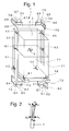
- Fig. 1 are for modeling the elastic Elevator car 1 at least two rigid bodies required namely cabin body 2 and cabin frame 3.
- Cabin body 2 and cabin frame 3 are by means of elastomer springs 4.1 to 4.6, the so-called cabin insulation 4 connected. This is reduced the transmission of structure-borne noise from the frame to the Cab body.
- cabin body and cabin frame As shown in Fig. 1 are for modeling the elastic Elevator car 1 at least two rigid bodies required namely cabin body 2 and cabin frame 3.
- Cabin body 2 and cabin frame 3 are by means of elastomer springs 4.1 to 4.6, the so-called cabin insulation 4 connected. This is reduced
- the transverse rigidity of cabin body 2 and cab frame 3 is much lower than the stiffness in Vertical direction. This can be done with the division in each at least two rigid bodies, namely cabin body 2.1 and 2.2 and cabin frames 3.1 and 3.2 are modeled.
- the at least two sub-bodies are horizontal by springs 5, 6.1 and 6.2 coupled and can be connected vertically as rigid to be viewed as.
- the guide rollers 7.1 to 7.8 with the proportionate masses of Levers and actuators can work with at least 8 rigid bodies modeled or neglected. This is dependent from the associated natural frequencies of the guide rollers and considered from the upper limit of the frequency range of becomes. Since the natural frequency of the actuator-roller system in Regulated condition can lead to instability, the Modeling with rigid bodies is preferred. These are only perpendicular to the footprint on the rail opposite the Sliding frame and with the roller guide springs 8.1 bis 8.8 coupled. In the other directions they are rigid with connected to the frame.
- the leadership behavior or the Force coupling between guide rollers and guide rails important. To model are essentially only the two horizontal force components necessary. The vertical one Force component that results from the rolling resistance can be ignored. The normal force results from the elastic compression of the roller covering 9.1 to 9.8. The Axial or lateral force results from the angle between the Straight lines perpendicular to the roll axis and parallel to the rail and the actual direction of movement of the Roll center.
- v K and F RN can be considered constant if the preload force is significantly greater than the dynamic part of the normal force. This means that the roller force in the axial direction is proportional and opposite to the speed in the axial direction and inversely proportional to the driving speed of the elevator car.
- Transverse vibrations of the cabin are thus due to the roles steamed as from a viscous damper, with the effect becomes smaller with increasing travel speed.
- the guide rollers 7 with a order an axle 10 'rotatable lever 10 with the cab frame 3 connected, wherein the roller guide spring 8 a force generated between the lever and cab frame.
- An actuator 11 generates a force parallel to the roller guide spring acts.
- a position sensor 12 measures the position of the lever 10 and the guide roller 7.
- An acceleration sensor 13th measures the acceleration of the cabin frame 3 perpendicular to Footprint of the roller lining 9 on the guide rail 14.
- the reference number of the respective element applies as in Fig. 1 shown (for example, on the elevator car 1 below right: 7.1.8.1.9.1,10.1,11.1,12.1,13.1).
- the Number of required acceleration sensors 13 corresponds the number of controlled axles, with at least three and at most six acceleration sensors are provided.
- an i is a triple of signals Fn i , Pn i , i for actuator force, position and acceleration.
- the index i is the consecutive numbering in the respective axis system and n stands for number of axes of the system.
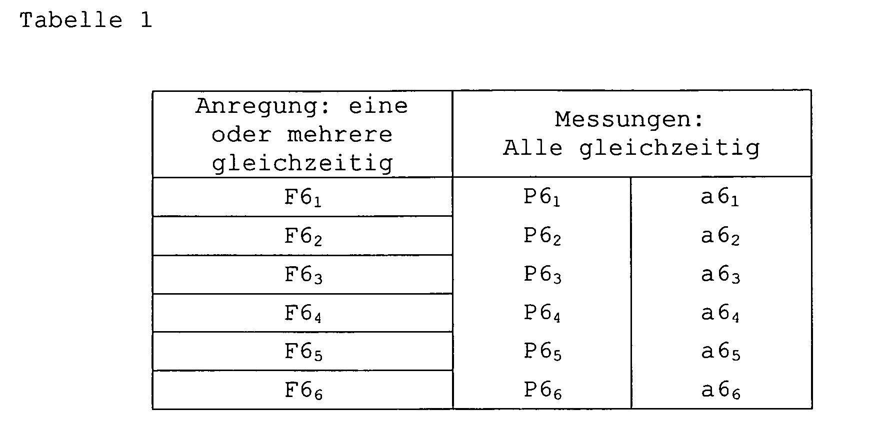
- one or more actuators are actuated with a force signal as shown in FIG. 11, and the elevator car 1 is excited to vibrations transverse to the direction of travel in such a way that clearly measurable signals are produced in the position sensors 12 and in the acceleration sensors 13. So that the correlation of the measurements with the force signals can be reliably determined, usually only one actuator or actuator pair is driven. As shown in Table 1, at least as many test drives are necessary as active axles are provided.
- the frequency spectrum of the force signals and the measured position signals and acceleration signals are determined by Fourier transformation.
- the transfer functions in the frequency domain or frequency responses G i , j ( ⁇ ) with the angular frequency ⁇ as an argument are determined by dividing the spectra of the measurements by the associated spectrum of the force signal.
- i the index of the measurement
- j the index of the force.
- G P i . j ( ⁇ ) P i ( ⁇ ) F j ( ⁇ )
- G a i . j ( ⁇ ) a i ( ⁇ ) F j ( ⁇ )
- G P i , j ( ⁇ ) are the individual frequency responses from force to position and G a i , j ( ⁇ ) are the individual frequency responses from force to acceleration.
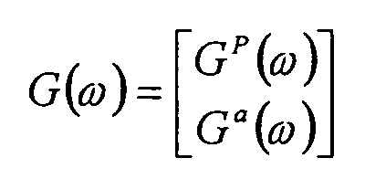
- the matrix G P ( ⁇ ) contains all frequency responses force to position and matrix G a ( ⁇ ) all frequency responses force to acceleration.
- Matrix G ( ⁇ ) arises from the vertical composition of G P ( ⁇ ) and G a ( ⁇ ).
- the vector x ⁇ contains the derivatives of x after the time.
- y is a vector containing the measured quantities, ie positions and accelerations.
- the vector u contains the inputs (actuator forces) of the system.
- A, B, C and D are matrices which together form the so-called Jacobian matrix by which a linear system is completely described.
- G ⁇ ( ⁇ ) is a matrix with the same number of rows as measurements in vector y and the same number of columns as inputs in vector u and contains all frequency responses of the MKS model of the cabin.
- a Jacobian matrix contains all partial derivatives of a System of equations.
- Coupled differential equations of 1st order are the constant coefficients of the A, B, C and D matrices.
- the model contains a number of well known parameters such as dimensions and mass and a number of poorly known parameters such as spring rates and damping constants. It is important to identify these poorly known parameters. The identification is performed by comparing the frequency responses of the model with the measured frequency responses. With an optimization algorithm, the poorly known model parameters are changed until the minimum of the sum e of all deviations of the frequency responses of the model from the measured frequency responses is found.
- w ( ⁇ ) is a frequency-dependent weighting. It ensures that only important parts of the measured frequency responses are modeled in the model.
- An optimization algorithm can briefly rewrite as follows Given is a function with multiple variables. We are looking for a minimum or maximum of this function. One Optimization algorithm searches for these extremes. There are many different algorithms, e.g. the method of the fastest Descent seeks the greatest gradient with the help of partial derivatives and finds local minima quickly, can but others overlook it. Optimization is in many Subject areas applied mathematics and an important area scientific research.
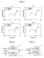
- Fig. 5 shows the frequency-dependent gains of the acceleration measured and of the identified model.
- means magnitude or amplitude of the transfer function or the frequency response force to acceleration with output acceleration of axis 1 and with input force of axis 1.
- the 11 shows the force signal for excitation of the actuators 11.
- the excitation takes place with a so-called Random Binary Signal generated by a random generator, the Amplitude of the signal fixed, for example to ⁇ 300 N. can be adjusted and the spectrum wide and is evenly distributed.
- the model with the identified parameters forms the Basis for the design of an optimal controller for active Vibration damping. Controller structure and parameters are depending on the characteristics of the track to be regulated, in this case of the elevator car.
- the elevator car has a static and dynamic behavior caused by the Model is described. Important parameters are: masses and Moments of inertia, geometry such as height (s), Width (s), depth (s), track gauge, etc., spring rates and Attenuation values. If the parameters change, so does that Influence on the behavior of the elevator car and thus on the settings of the vibration damping controller.
- at a classic PID controller proportional, integral and Differential control
- the regulator for the present case has well over a hundred parameters, with a Manual adjustment is practically impossible. The Parameters must therefore be determined automatically. This is only with the help of a model that is the essential Describes characteristics of the elevator car, possible.
- a dynamic system is time-invariant when the descriptive parameters remain constant.
- a linear one Controller is time-invariant when system matrices A, B, C and D not change. Controller on a digital computer are realized are always time-discrete. That means, you make the inputs, calculations and outputs in fixed Intervals.
- Fig. 8 shows the signal flow scheme of the closed-loop H ⁇ drafting process.
- the main advantage of the H ⁇ design process is that it can be automated. Standard minimizes the system to be controlled with a closed loop -
- the H ⁇ is.
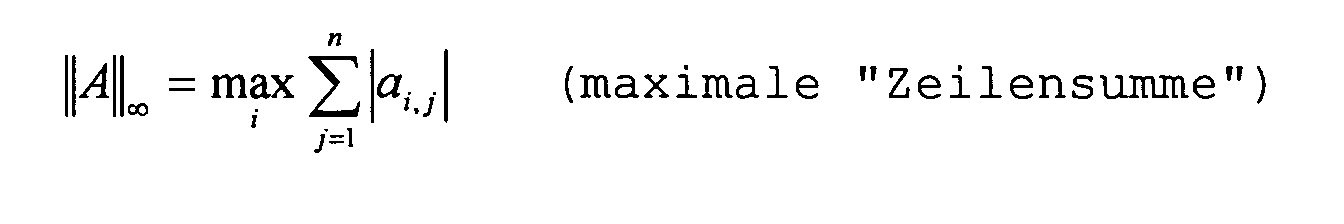
- the H ⁇ - norm of a matrix A with m ⁇ n elements is given by:
- Fig. 8 is a diagram for designing the regulator with the H ⁇ method.
- w is the vector signal at the input and is composed of v and r.
- T consists of controller, control section and weighting functions.
- P6 or a6 constitute the closed-loop feedback, the position controller or the accelerometer separately designed.
- F6 is the output or the control signal of the controller.
- Singular values are a measure of the overall gain of a Matrix.
- An n x n matrix has n singular values.
Landscapes
- Cage And Drive Apparatuses For Elevators (AREA)
- Lift-Guide Devices, And Elevator Ropes And Cables (AREA)
- Elevator Control (AREA)
Abstract
Description
Die Erfindung betrifft ein Verfahren für den Entwurf eines Reglers zur Schwingungsdämpfung an einer Aufzugskabine, wobei der Reglerentwurf auf einem Modell der Aufzugskabine basiert.The invention relates to a method for the design of a Regulator for vibration damping in an elevator car, wherein the regulator design is based on a model of the elevator cabin.
Mit der Patentschrift EP 0 731 051 B1 ist eine Einrichtung
und ein Verfahren zur Schwingungsdämpfung an einer
Aufzugskabine bekannt geworden. Quer zur Fahrtrichtung
auftretende Schwingungen bzw. Beschleunigungen werden durch
eine schnelle Regelung reduziert, sodass sie in der
Aufzugskabine nicht mehr spürbar sind. Zur Erfassung der
Messwerte sind am Kabinenrahmen Trägheitssensoren angeordnet.
Ausserdem führt ein langsamer Positionsregler die
Aufzugskabine bei einseitiger Schieflage gegenüber den
Führungsschienen selbsttätig in eine Mittellage nach, wobei
Positionssensoren die Messwerte an Positionsregler liefern.
Zur Reduktion der Schwingungen bzw. der Beschleunigungen an der Aufzugskabine sind ein Mehrgrössenregler und ein weiterer Mehrgrössenregler zur Aufrechthaltung des Spiels an den Führungsrollen bzw. der aufrechten Lage der Aufzugskabine vorgesehen. Die Stellsignale der beiden Regler werden addiert und steuern je einen Aktuator pro Rollenführung und pro Horizontalrichtung. To reduce the vibrations or accelerations The elevator car is a multi-size controller and another Multi-size controller for maintaining the game to the Guide rollers or the upright position of the elevator car intended. The control signals of the two controllers are added and control one actuator per roller guide and per Horizontal direction.
Der Reglerentwurf basiert auf einem Modell der Aufzugskabine, welches die wesentlichen Strukturresonanzen berücksichtigt.The controller design is based on a model of the elevator car, which takes into account the essential structural resonances.
Nachteilig ist, dass das Gesamtmodell zu grosser Komplexität neigt, trotz ausgefeilter Methoden zur Reduktion der Anzahl Pole. Als Folge davon wird der modellbasierte Regler ebenfalls komplex.The disadvantage is that the overall model is too complex tends, despite sophisticated methods for reducing the number Poles. As a result, the model-based controller becomes also complex.
Hier will die Erfindung Abhilfe schaffen. Die Erfindung, wie
sie in Anspruch 1 gekennzeichnet ist, löst die Aufgabe, die
Nachteile des bekannten Verfahrens zu vermeiden und ein
einfaches Verfahren für den Entwurf eines Reglers
vorzuschlagen.The invention aims to remedy this situation. The invention, how
it is characterized in
Vorteilhafte Weiterbildungen der Erfindung sind in den abhängigen Patentansprüchen angegeben.Advantageous developments of the invention are in the specified dependent claims.
Vorteilhafterweise wird beim erfindungsgemässen Verfahren ein Gesamtmodell der Aufzugskabine mit bekannter Struktur vorgegeben. Es handelt sich dabei um ein sogenanntes Mehrkörpersystem (MKS) Modell, welches mehrere starre Körper umfasst. Das MKS Modell beschreibt die wesentliche elastische Struktur der Aufzugskabine mit den Führungsrollen und den Aktuatoren sowie die Kraftkoppelung mit den Führungsschienen. Die Modellparameter sind mehr oder weniger gut bekannt oder es liegen Schätzungen vor, wobei die Parameter für die verwendete Aufzugskabine zu identifizieren bzw. zu bestimmen sind. Dabei werden die Übertragungsfunktionen bzw. Frequenzgänge des Modells mit den gemessenen Übertragungsfunktionen bzw. Frequenzgängen verglichen. Mit Hilfe eines Algorithmus zur Optimierung von Funktionen mit mehreren Variablen werden die geschätzten Modellparameter verändert um grösstmögliche Übereinstimmung zu erzielen.Advantageously, in the inventive method a Overall model of the elevator car with known structure specified. It is a so-called Multibody (MBS) model, which has several rigid bodies includes. The MKS model describes the essential elastic Structure of the elevator car with the guide rollers and the Actuators and the power coupling with the guide rails. The model parameters are more or less well known or there are estimates, the parameters for the used to identify or determine the elevator car used are. The transfer functions or Frequency responses of the model with the measured Transmission functions or frequency responses compared. With Help of an algorithm to optimize functions with several variables are the estimated model parameters changed in order to achieve the greatest possible agreement.
Weiter vorteilhaft ist, dass als Messeinrichtung für die zu messenden Übertragungsfunktionen bzw. Frequenzgänge das aktive Schwingungsdämpfungssystem der Aufzugskabine selbst verwendbar ist. Mit den Aktuatoren wird die Aufzugskabine angeregt und mit den Beschleunigungssensoren bzw. mit den Positionssensoren werden die Antworten gemessen.Next advantageous is that as a measuring device for the measuring transmission functions or frequency responses the active vibration damping system of the elevator car itself is usable. With the actuators is the elevator car stimulated and with the acceleration sensors or with the Position sensors are measured the answers.
Diese modellbasierte Entwurfsmethode des Reglers gewährleistet die bestmögliche aktive Schwingungsdämpfung für die einzelnen Aufzugskabinen mit sehr unterschiedlichen Parametern.This model-based design method of the controller ensures the best possible active vibration damping for the individual elevator cabins with very different ones Parameters.
Mit oben genanntem Identifikationsverfahren wird sichergestellt, dass als Resultat das einfachste und konsistenteste Modell der Aufzugskabine vorliegt. Vorteilhafterweise hat der auf diesem Modell basierende Regler eine bessere Güte bzw. eine bessere Regelqualität. Ausserdem ist das Verfahren systematisch beschreibbar und lässt sich weitgehend automatisieren und in wesentlich kürzerer Zeit durchführen.With above-mentioned identification method is ensured that as a result the simplest and most most consistent model of the elevator car is present. Advantageously, based on this model Controller better quality and better control quality. In addition, the method is systematically writable and is largely automated and essential perform a shorter time.
Basierend auf dem MKS Modell mit identifizierten Parametern wird ein robuster Mehrgrössenregler entworfen zur Reduktion der Beschleunigung und ein Positionsregler zur Aufrechterhaltung des Spiels an den Führungsrollen.Based on the MKS model with identified parameters a robust multi-size controller is designed for reduction acceleration and a position regulator for Maintaining the game on the leadership roles.
Der Beschleunigungsregler hat das Verhalten eines Bandpassfilters und die beste Wirkung in einem mittleren Frequenzbereich von etwa 1 Hz bis 4 Hz. Unterhalb und oberhalb dieses Frequenzbandes wird die Verstärkung und damit die Wirksamkeit des Beschleunigungsreglers reduziert.The acceleration controller has the behavior of a Bandpass filters and the best effect in a medium Frequency range from about 1 Hz to 4 Hz. Below and above this frequency band is the gain and thus reduces the effectiveness of the acceleration regulator.
Im tiefen Frequenzbereich wird die Wirkung des Beschleunigungsreglers durch das verfügbare Spiel an den Führungsrollen und den darauf auszulegenden Positionsregler begrenzt. Der Positionsregler bewirkt, dass die Aufzugskabine einem Mittelwert der Schienenprofile folgt, während der Beschleunigungsregler eine geradlinige Bewegung bewirkt. Dieser Zielkonflikt wird gelöst, indem die beiden Regler in unterschiedlichen Frequenzbereichen wirksam sind. Die Verstärkung des Positionsreglers ist bei tiefen Frequenzen gross und nimmt dann ab. Das heisst, er hat die Eigenschaft eines Tiefpassfilters. Umgekehrt hat der Beschleunigungsregler bei tiefen Frequenzen eine kleine Verstärkung.In the low frequency range, the effect of the Acceleration controller through the available game to the Guide rollers and the position controller to be interpreted thereon limited. The position controller causes the elevator car an average of the rail profiles follows while the Accelerator causes a rectilinear motion. This conflict of objectives is resolved by turning the two knobs in different frequency ranges are effective. The Gain of the positioner is at low frequencies big and then decreases. That is, he has the property a low-pass filter. Conversely, the Acceleration controller at low frequencies a small Gain.
Im hohen Frequenzbereich wird die Wirkung des Beschleunigungsreglers durch die Elastizität der Aufzugskabine begrenzt. Die erste Strukturresonanz kann beispielsweise bei 12 Hz auftreten, wobei dieser Wert stark von der Bauweise der Aufzugskabine abhängig ist und deutlich tiefer liegen kann. Oberhalb der ersten Strukturresonanz kann der Regler die Beschleunigung am Kabinenkörper nicht mehr reduzieren. Es besteht sogar die Gefahr, dass Strukturresonanzen angeregt werden, oder dass Instabilität auftreten kann. Mit Kenntnis des dynamischen Systemmodells der Regelstrecke kann der Regler so ausgelegt werden, dass dies vermieden werden kann. In the high frequency range, the effect of the Acceleration controller by the elasticity of the Elevator car limited. The first structural resonance can For example, at 12 Hz, this value is strong depends on the construction of the elevator car and clearly can be lower. Above the first structural resonance can the controller no longer accelerates the car body to reduce. There is even a risk that Structural resonances are stimulated, or that instability can occur. With knowledge of the dynamic system model the controller, the controller can be designed so that this can be avoided.
Anhand der beiliegenden Figuren wird die vorliegende Erfindung näher erläutert:With reference to the accompanying figures, the present Invention explained in more detail:
Es zeigen:
ein Mehrkörpersystem (MKS) Modell einer Aufzugskabine,
eine Führungsrolle mit Rollenkräften,
ein Stellglied mit Führungsrolle, Aktuator und Sensoren,
eine schematische Darstellung der geregelten Achsen,
die Verstärkung der gemessenen Beschleunigung und des identifizierten Modells,
einen optimierten Regler mit den identifizierten Parametern zur aktiven Schwingungsdämpfung,
Signalflussschema für den Entwurf eines H ∞-Reglers mit Regler und Regelstrecke,
den Verlauf der Singularwerte eines Positionsreglers in y-Richtung,
den Verlauf der Singularwerte eines Beschleunigungsreglers in y-Richtung und
a multi-body system (MBS) model of an elevator car,
a leadership role with role forces,
an actuator with guide roller, actuator and sensors,
a schematic representation of the controlled axes,
the gain of the measured acceleration and the identified model,
an optimized controller with the identified parameters for active vibration damping,
Signal flow diagram for the design of H ∞ knob with controller and control loop,
the course of the singular values of a position controller in the y-direction,
the course of the singular values of an acceleration controller in the y-direction and
Das MKS Modell muss die wesentlichen Eigenschaften der Aufzugskabine bezüglich Fahrkomfort wiedergeben. Da bei der Identifikation der Parameter nur mit linearen Modellen gearbeitet werden kann, müssen alle nichtlinearen Effekte vernachlässigt werden. Die ersten Eigenfrequenzen der elastischen Aufzugkabine liegen so tief, dass sie sich mit den sogenannten Starrkörper-Eigenfrequenzen der Gesamtkabine überschneiden können.The MKS model must have the essential characteristics of Regulate elevator car regarding ride comfort. Since at the Identification of parameters only with linear models All nonlinear effects must be able to be worked be ignored. The first natural frequencies of the elastic elevator cabins are so deep that they are with the so-called rigid body natural frequencies of the entire cabin can overlap.
Wie in Fig. 1 gezeigt sind zur Modellierung der elastischen
Aufzugskabine 1 mindestens zwei starre Körper erforderlich,
nämlich Kabinenkörper 2 und Kabinenrahmen 3. Kabinenkörper 2
und Kabinenrahmen 3 sind mittels Elastomerfedern 4.1 bis 4.6,
der sogenannten Kabinenisolation 4 verbunden. Diese reduziert
die Übertragung von Körperschall vom Rahmen auf den
Kabinenkörper. Zur Modellierung einer starren Aufzugskabine 1
genügt es, Kabinenkörper und Kabinenrahmen gesamthaft als
einen Körper zu betrachten.As shown in Fig. 1 are for modeling the
Die Quersteifigkeit von Kabinenkörper 2 und von Kabinenrahmen
3 ist wesentlich geringer als die Steifigkeit in
Vertikalrichtung. Dies kann mit der Aufteilung in je
mindestens zwei Starrkörper, nämlich Kabinenkörper 2.1 und
2.2 und Kabinenrahmen 3.1 und 3.2 modelliert werden. Die
mindestens zwei Teilkörper sind horizontal durch Federn 5,
6.1 und 6.2 gekoppelt und können vertikal als starr verbunden
betrachtet werden.The transverse rigidity of
Die Führungsrollen 7.1 bis 7.8 mit den anteiligen Massen von Hebeln und Aktuatoren können mit mindestens 8 Starrkörpern modelliert oder auch vernachlässigt werden. Dies ist abhängig von den zugehörigen Eigenfrequenzen der Führungsrollen und von der oberen Grenze des Frequenzbereiches der betrachtet wird. Da die Eigenfrequenz des Aktuator-Rolle-Systems im geregelten Zustand zu Instabilität führen kann, wird die Modellierung mit Starrkörpern bevorzugt. Diese sind nur senkrecht zur Aufstandsfläche an der Schiene gegenüber dem Rahmen verschiebbar und mit den Rollenführungsfedern 8.1 bis 8.8 gekoppelt. In den anderen Richtungen sind sie starr mit dem Rahmen verbunden.The guide rollers 7.1 to 7.8 with the proportionate masses of Levers and actuators can work with at least 8 rigid bodies modeled or neglected. This is dependent from the associated natural frequencies of the guide rollers and considered from the upper limit of the frequency range of becomes. Since the natural frequency of the actuator-roller system in Regulated condition can lead to instability, the Modeling with rigid bodies is preferred. These are only perpendicular to the footprint on the rail opposite the Sliding frame and with the roller guide springs 8.1 bis 8.8 coupled. In the other directions they are rigid with connected to the frame.
Wie in Fig. 2 gezeigt ist das Führungsverhalten bzw. die Kraftkoppelung zwischen Führungsrollen und Führungsschienen wichtig. Zur Modellbildung sind im wesentlichen nur die zwei horizontalen Kraftkomponenten notwendig. Die vertikale Kraftkomponente, die aus dem Rollwiderstand resultiert, kann vernachlässigt werden. Die Normalkraft ergibt sich aus der elastischen Kompression des Rollenbelages 9.1 bis 9.8. Die Axial- oder Querkraft ergibt sich aus dem Winkel zwischen der Geraden senkrecht zur Rollenachse und parallel zur Schiene und der tatsächlichen Bewegungsrichtung des Rollenmittelpunktes.As shown in Fig. 2, the leadership behavior or the Force coupling between guide rollers and guide rails important. To model are essentially only the two horizontal force components necessary. The vertical one Force component that results from the rolling resistance can be ignored. The normal force results from the elastic compression of the roller covering 9.1 to 9.8. The Axial or lateral force results from the angle between the Straight lines perpendicular to the roll axis and parallel to the rail and the actual direction of movement of the Roll center.
Mathematisch sind folgende Zusammenhänge relevant:
- FRA
- : Rollenkraft in Achsrichtung in [N]
- α
- : Schräglaufwinkel in [rad]
- FRN
- : Rollenkraft normal zur Aufstandsfläche [N]
- K
- : Konstante ohne Dimension, wird durch Messung bestimmt
- F RA
- : Rolling force in axial direction in [N]
- α
- : Slip angle in [rad]
- F RN
- : Roller Force Normal to Contact Area [N]
- K
- : Constant without dimension, determined by measurement
Das Kraftgesetz {1} wird spätestens dann ungültig, wenn die Grenzen der Haftreibungskraft erreicht werden sowie bei grossem Schräglaufwinkel α. Dieser wird bei kleiner Fahrgeschwindigkeit schnell grösser und beträgt im Stillstand ungefähr 90 Grad. Das Kraftgesetz {1} gilt also nur für die fahrende Kabine.The force law {1} becomes invalid at the latest when the Limits of static friction can be achieved as well large slip angle α. This one becomes smaller Driving speed quickly greater and is at a standstill about 90 degrees. The law of force {1} only applies to the moving cabin.
Für die Rollenkraft in Achsrichtung bei fahrender Kabine gilt
dann näherungsweise:
- vK :
- Vertikalgeschwindigkeit der Kabine [m/s]
- vA :
- Geschwindigkeit der Kabine in Achsrichtung [m/s]
- v K :
- Vertical speed of the cabin [m / s]
- v A :
- Speed of the cabin in the axial direction [m / s]
K ist eine Konstante, vK und FRN können als konstant betrachtet werden, wenn die Vorspannkraft deutlich grösser als der dynamische Anteil der Normalkraft ist. Das bedeutet, dass die Rollenkraft in Achsrichtung proportional und entgegengesetzt zur Geschwindigkeit in Achsrichtung und umgekehrt proportional zur Fahrgeschwindigkeit der Aufzugskabine ist.K is a constant, v K and F RN can be considered constant if the preload force is significantly greater than the dynamic part of the normal force. This means that the roller force in the axial direction is proportional and opposite to the speed in the axial direction and inversely proportional to the driving speed of the elevator car.
Querschwingungen der Kabine werden also durch die Rollen gedämpft wie von einem viskosen Dämpfer, wobei die Wirkung mit zunehmender Fahrgeschwindigkeit kleiner wird.Transverse vibrations of the cabin are thus due to the roles steamed as from a viscous damper, with the effect becomes smaller with increasing travel speed.
Wie in Fig. 3 gezeigt sind die Führungsrollen 7 mit einem um
eine Achse 10' drehbaren Hebel 10 mit dem Kabinenrahmen 3
verbunden, wobei die Rollenführungsfeder 8 eine Kraft
zwischen Hebel und Kabinenrahmen erzeugt. Ein Aktuator 11
erzeugt eine Kraft die parallel zur Rollenführungsfeder
wirkt. Ein Positionssensor 12 misst die Position des Hebels
10 bzw. der Führungsrolle 7. Ein Beschleunigungssensor 13
misst die Beschleunigung des Kabinenrahmens 3 senkrecht zur
Aufstandsfläche des Rollenbelags 9 auf der Führungsschiene
14. Das Bezugszeichen des jeweiligen Elementes gilt wie in
Fig. 1 gezeigt (beispielsweise an der Aufzugskabine 1 unten
rechts: 7.1,8.1,9.1,10.1,11.1,12.1,13.1).As shown in Fig. 3, the
An der Aufzugskabine 1 sind vier untere Führungsrollen 7.1
bis 7.4 mit Aktuatoren und Positionssensoren vorgesehen.
Zusätzlich können auch vier obere Führungsrollen 7.5 bis 7.8
mit Aktuatoren und Positionssensoren vorgesehen sein. Die
Anzahl der benötigten Beschleunigungssensoren 13 entspricht
der Anzahl der geregelten Achsen, wobei mindestens drei und
höchstens sechs Beschleunigungssensoren vorgesehen sind. At the
Wie in Fig. 4 gezeigt wird für die aktive Schwingungsdämpfung
der Aufzugskabine 1 die Zahl der Achsen von acht auf sechs
reduziert, oder von vier auf drei Achsen, wenn nur unten
aktiv geregelt wird. Zu jeder Achse Ani gehört ein Tripel von
Signalen Fni, Pni, ani für Aktuatorkraft, Position und
Beschleunigung. Der Index i ist die fortlaufende Numerierung
im jeweiligen Achsensystem und n steht für Zahl der Achsen
des Systems.As shown in Fig. 4, for the active vibration damping of the
Die Signale des unteren und des oberen Rollenpaars zwischen
den Führungsschienen 14.1 bzw. 14.2 werden folgendermassen
zusammengefasst:
Bei den Messfahrten werden ein oder mehrere Aktuatoren mit
einem Kraftsignal wie in Fig. 11 gezeigt angesteuert und die
Aufzugskabine 1 zu Vibrationen quer zur Fahrtrichtung so
angeregt, dass deutlich messbare Signale in den
Positionssensoren 12 und in den Beschleunigungssensoren 13
entstehen. Damit die Korrelation der Messungen mit den
Kraftsignalen zuverlässig bestimmt werden kann, wird
üblicherweise nur ein Aktuator oder Aktuatorpaar angesteuert.
Wie in Tabelle1 gezeigt sind dann mindestens so viele
Messfahrten notwendig wie aktive Achsen vorgesehen sind.
Das Frequenzspektrum der Kraftsignale sowie der gemessenen
Positionssignale und Beschleunigungssignale werden durch
Fouriertransformation bestimmt. Die Übertragungsfunktionen im
Frequenzbereich oder Frequenzgänge G i,j (ω) mit der
Kreisfrequenz ω als Argument, werden bestimmt, indem die
Spektren der Messungen durch das zugehörige Spektrum des
Kraftsignals dividiert werden. Dabei ist i der Index der
Messung und j der Index der Kraft.
G P i,j (ω) sind die einzelnen Frequenzgänge von Kraft zu Position und G a i,j (ω) sind die einzelnen Frequenzgänge von Kraft zu Beschleunigung. Die Matrix G P (ω) enthält alle Frequenzgänge Kraft zu Position und Matrix G a (ω) alle Frequenzgänge Kraft zu Beschleunigung. Matrix G(ω) entsteht aus der vertikalen Zusammensetzung von G P (ω) und G a (ω). G P i , j (ω) are the individual frequency responses from force to position and G a i , j (ω) are the individual frequency responses from force to acceleration. The matrix G P (ω) contains all frequency responses force to position and matrix G a (ω) all frequency responses force to acceleration. Matrix G (ω) arises from the vertical composition of G P (ω) and G a (ω).
Für ein 6-Achsensystem resultieren so 2 x 6 x 6 = 72 Übertragungsfunktionen und für ein 3-Achsensystem 2 x 3 x 3 = 18 Übertragungsfunktionen. Bei Kabinen deren Schwerpunkt auf der Achse zwischen den Führungsschienen 14.1 und 14.2 liegt, sind die Kopplungen und die Korrelation zwischen den beiden horizontalen Richtungen x und y schwach. Darum wird nur ungefähr die Hälfte der Übertragungsfunktionen weiterverwendet, die übrigen scheiden aus, wegen ungenügender Korrelation.For a 6-axis system, this results in 2 x 6 x 6 = 72 Transfer functions and for a 3-axis system 2 x 3 x 3 = 18 transfer functions. In cabins their focus on the axis lies between the guide rails 14.1 and 14.2, are the couplings and the correlation between the two horizontal directions x and y weak. That's why only about half of the transfer functions continue to use, the rest are eliminated, because of insufficient Correlation.
Das MKS Modell der Kabine ist im Allgemeinen ein lineares
System. Falls dieses nichtlineare Teile enthält wird durch
numerische Differenzbildung ein vollständig linearisiertes
Modell in einem geeigneten Betriebszustand erzeugt. Im
linearen Zustandsraum wird das MKS Modell mit folgenden
Gleichungen beschrieben:
x ist der Vektor der Zustände des Systems, welche im
Allgemeinen von aussen nicht sichtbar sind. Zustände des
Systems sind im vorliegenden Fall:
Der Vektor x ˙ enthält die Ableitungen von x nach der Zeit. y
ist ein Vektor, der die gemessenen Grössen enthält, also
Positionen und Beschleunigungen. Der Vektor u enthält die
Eingänge (Aktuatorkräfte) des Systems. A,B,C und D sind
Matrizen welche zusammen die sogenannte Jacobimatrix bilden
durch die ein lineares System vollständig beschrieben wird.
Die Frequenzantwort des Systems ist gegeben durch
G^(ω) ist eine Matrix mit gleich vielen Zeilen wie Messungen im Vektor y und gleich vielen Spalten wie Eingänge im Vektor u und enthält alle Frequenzgänge des MKS Modells der Kabine. G ^ (ω) is a matrix with the same number of rows as measurements in vector y and the same number of columns as inputs in vector u and contains all frequency responses of the MKS model of the cabin.
Eine Jacobibatrix enthält alle partiellen Ableitungen eines Systems von Gleichungen. Bei einem linearen System von gekoppelten Differenzialgleichungen 1. Ordnung sind das die konstanten Koeffizienten der A,B,C und D Matrizen.A Jacobian matrix contains all partial derivatives of a System of equations. In a linear system of Coupled differential equations of 1st order are the constant coefficients of the A, B, C and D matrices.
Das Modell enthält eine Anzahl gut bekannter Parameter wie
beispielsweise Abmessungen und Masse und eine Anzahl schlecht
bekannter Parameter wie beispielsweise Federraten und
Dämpfungskonstanten. Diese schlecht bekannten Parameter gilt
es zu identifizieren. Die Identifikation wird durchgeführt,
indem die Frequenzgänge des Modells mit den gemessenen
Frequenzgängen verglichen werden. Mit einem
Optimierungsalgorithmus werden die schlecht bekannten
Modellparameter solange verändert bis das Minimum der Summe
e aller Abweichungen der Frequenzgänge des Modells von den
gemessenen Frequenzgängen gefunden wird.

Ein Optimierungsalgorithmus kann wie folgt kurz umschreiben werden: Gegeben ist eine Funktion mit mehreren Variablen. Gesucht wird ein Minimum oder Maximum dieser Funktion. Ein Optimierungsalgorithmus sucht diese Extrema. Es gibt viele verschiedene Algorithmen, z.B. die Methode des schnellsten Abstiegs sucht den grössten Gradienten mit Hilfe der partiellen Ableitungen und findet lokale Minima schnell, kann dafür aber andere übersehen. Optimierung ist in vielen Fachgebieten angewandte Mathematik und ein wichtiges Gebiet wissenschaftlicher Forschung.An optimization algorithm can briefly rewrite as follows Given is a function with multiple variables. We are looking for a minimum or maximum of this function. One Optimization algorithm searches for these extremes. There are many different algorithms, e.g. the method of the fastest Descent seeks the greatest gradient with the help of partial derivatives and finds local minima quickly, can but others overlook it. Optimization is in many Subject areas applied mathematics and an important area scientific research.
Fig. 5 zeigt die frequenzabhängigen Verstärkungen der
Beschleunigung gemessen und vom identifizierten Modell.
|Ga 1,1| bedeutet Betrag oder Amplitude der
Übertragungsfunktion bzw. des Frequenzganges Kraft zu
Beschleunigung mit Ausgang Beschleunigung von Achse 1 und mit
Eingang Kraft von Achse 1. Dimension: 1 mg/N = 1 milli-g/N =
0.0981 m/s^2/N ~ 1 cm/s^2/N.Fig. 5 shows the frequency-dependent gains of the acceleration measured and of the identified model. | G a 1,1 | means magnitude or amplitude of the transfer function or the frequency response force to acceleration with output acceleration of
Fig. 11 zeigt das Kraftsignal zur Anregung der Aktuatoren 11.
Die Anregung erfolgt mit einem sogenannten Random Binary
Signal, das mittels Zufallsgenerator erzeugt wird, wobei die
Amplitude des Signals fest, beispielsweise auf ±300 N
eingestellt werden kann und das Spektrum breit und
gleichmässig verteilt ist.11 shows the force signal for excitation of the
Das Modell mit den identifizierten Parametern bildet die Grundlage für den Entwurf eines optimalen Reglers zur aktiven Schwingungsdämpfung. Reglerstruktur und -Parameter sind abhängig von den Eigenschaften der zu regelnden Strecke, in diesem Fall von der Aufzugskabine. Die Aufzugskabine hat ein statisches und dynamisches Verhalten, welches durch das Modell beschrieben wird. Wichtige Parameter sind: Massen und Massenträgheitsmomente, Geometrie wie beispielsweise Höhe(n), Breite(n), Tiefe(n), Spurmass usw., Federraten und Dämpfungswerte. Ändern sich die Parameter, so hat das Einfluss auf das Verhalten der Aufzugskabine und damit auf die Einstellungen des Reglers zur Schwingungsdämpfung. Bei einem klassischen PID-Regler (Proportional-, Integral- und Differential-Regler) sind drei Verstärkungen einzustellen, was sich manuell gut bewältigen lässt. Der Regler für den vorliegenden Fall hat weit über hundert Parameter, wobei eine manuelle Einstellung praktisch nicht mehr möglich ist. Die Parameter müssen deshalb automatisch ermittelt werden. Dies ist nur mit Hilfe von einem Modell, das die wesentlichen Eigenschaften der Aufzugskabine beschreibt, möglich.The model with the identified parameters forms the Basis for the design of an optimal controller for active Vibration damping. Controller structure and parameters are depending on the characteristics of the track to be regulated, in this case of the elevator car. The elevator car has a static and dynamic behavior caused by the Model is described. Important parameters are: masses and Moments of inertia, geometry such as height (s), Width (s), depth (s), track gauge, etc., spring rates and Attenuation values. If the parameters change, so does that Influence on the behavior of the elevator car and thus on the settings of the vibration damping controller. at a classic PID controller (proportional, integral and Differential control) are three reinforcements set, which can be managed manually well. The regulator for the present case has well over a hundred parameters, with a Manual adjustment is practically impossible. The Parameters must therefore be determined automatically. This is only with the help of a model that is the essential Describes characteristics of the elevator car, possible.
Die Regelung wie in Fig. 6 gezeigt ist aufgeteilt in zwei
parallel geschaltete Regler:
Die aufdatierten Zustände x(n+1) für den nächsten Zeitschritt werden berechnet, damit sie dort zur Verfügung stehen.The updated states x (n + 1) for the next time step are calculated to be available there.
Ein dynamisches System ist zeitinvariant, wenn die beschreibenden Parameter konstant bleiben. Ein linearer Regler ist zeitinvarint, wenn die Systemmatrizen A,B,C und D sich nicht ändern. Regler die auf einem digitalen Rechner realisiert sind, sind immer auch zeitdiskret. Das heisst sie machen die Eingaben, Berechnungen und Ausgaben in festen Zeitabständen.A dynamic system is time-invariant when the descriptive parameters remain constant. A linear one Controller is time-invariant when system matrices A, B, C and D not change. Controller on a digital computer are realized are always time-discrete. That means, you make the inputs, calculations and outputs in fixed Intervals.
Beim Reglerentwurf wird die sogenannte H ∞ Methode verwendet.
Fig. 8 zeigt das Signalflussschema des H ∞-Entwurfsverfahrens
mit geschlossenem Regelkreis. Hauptvorteil des H ∞
Entwurfsverfahrens ist, dass es sich automatisieren lässt.
Dabei wird die H ∞- Norm des zu regelnden Systems mit
geschlossenem Regelkreis minimiert. Die H ∞- Norm einer
Matrix A mit m×n Elementen ist gegeben durch:
Beim zu regelnden System handelt es sich um das identifizierte Modell der Aufzugskabine 1 mit der Bezeichnung P für Plant wie in Fig. 8 gezeigt. Das gewünschte Verhalten des Reglers K mit Bezugszeichen 17 wird mit Hilfe von zusätzlichen Gewichtungsfunktionen am Eingang und am Ausgang des Systems erzeugt.
- wv modelliert die Störungen im Frequenzbereich am Eingang des Systems
- wr ist ein kleiner konstanter Wert
- wu limitiert den Reglerausgang
- wy hat den Wert eins
- w v models the disturbances in the frequency domain at the input of the system
- w r is a small constant value
- w u limits the controller output
- w y has the value one
Fig. 8 ist ein Schema zum Entwurf des Reglers mit der H ∞-Methode.
w ist das Vektorsignal am Eingang und ist aus v und
r zusammengesetzt. z ist das Vektorsignal am Ausgang, wobei
gilt z = T*w. T setzt sich zusammen aus Regler, Regelstecke
und Gewichtungsfunktionen. P6 oder a6 bilden die Rückführung
im geschlossenen Regelkreis, beim getrennten Entwurf vom
Positionsregler oder vom Beschleunigungsregler. F6 ist der
Ausgang oder das Stellsignal des Reglers.
Minimiert wird die H ∞-Norm von ∥z∥∞ / ∥w∥∞ = ∥T∥∞ Dazu
wird wiederum ein Optimierungsalgorithmus benötigt, der die
Parameter des Reglers solange ändert bis ein Minimum gefunden
wurde.Fig. 8 is a diagram for designing the regulator with the H ∞ method. w is the vector signal at the input and is composed of v and r. z is the vector signal at the output, where z = T * w. T consists of controller, control section and weighting functions. P6 or a6 constitute the closed-loop feedback, the position controller or the accelerometer separately designed. F6 is the output or the control signal of the controller.
The H ∞ -norm of ∥z∥ ∞ / ∥w∥ ∞ = ∥T∥ ∞ is minimized. Again, an optimization algorithm is needed that changes the parameters of the controller until a minimum is found.
Fig. 9 zeigt den Verlauf der Singularwerte eines Positionsreglers in y-Richtung. Dieser hat vorwiegend ein integrierendes Verhalten.9 shows the course of the singular values of a Position controller in y direction. This one has predominantly one integrating behavior.
Fig. 10 zeigt den Verlauf der Singularwerte eines Beschleunigungsreglers in y-Richtung. Dieser hat eine Bandpasscharakteristik.10 shows the course of the singular values of a Acceleration controller in y-direction. This one has one Bandpass characteristic.
Singularwerte sind ein Mass für die Gesamtverstärkung einer Matrix. Eine n x n Matrix hat n Singularwerte. Dimension: 1 N/mg = 1 N/milli-g = N/(0.0981 m/s^2) ~ 1 N/(cm/s^2).Singular values are a measure of the overall gain of a Matrix. An n x n matrix has n singular values. Dimension: 1 N / mg = 1 N / milli-g = N / (0.0981 m / s ^ 2) ~ 1 N / (cm / s ^ 2).
Claims (10)
dadurch gekennzeichnet, dass ein Gesamtmodell der Aufzugskabine (1) mit mehr oder weniger gut bekannten oder geschätzten Modellparametern verwendet wird, wobei die Parameter für die verwendete Aufzugskabine identifiziert werden durch Vergleich der Übertragungsfunktionen bzw. der Frequenzgänge des Modells mit den gemessenen Übertragungsfunktionen bzw. den gemessenen Frequenzgängen und die Modellparameter verändert werden um grösstmögliche Übereinstimmung mit den gemessenen Frequenzgängen zu erzielen, wobei das Modell mit den identifizierten Parametern als Grundlage für den Entwurf eines optimalen Reglers zur aktiven Schwingungsdämpfung dient.Method for the design of a vibration damping controller on an elevator car (1), the controller design being based on a model of the elevator car (1),
characterized in that an overall model of the elevator car (1) with more or less well known or estimated model parameters is used, wherein the parameters for the elevator car used are identified by comparing the transmission functions or the frequency responses of the model with the measured transmission functions or the measured ones Frequency response and the model parameters are changed in order to achieve the greatest possible match with the measured frequency responses, with the model with the identified parameters as the basis for the design of an optimal controller for active vibration damping is used.
dadurch gekennzeichnet, dass als Messeinrichtung für die zu messenden Übertragungsfunktionen bzw. Frequenzgänge das aktive Schwingungsdämpfungssystem der Aufzugskabine (1) selbst vorgesehen ist, wobei die Aufzugskabine (1) mittels Aktuatoren (11) angeregt wird und mittels Beschleunigungssensoren (13) bzw. mittels Positionssensoren (12) die Antworten gemessen werden. Method according to claim 1,
characterized in that the active vibration damping system of the elevator car (1) itself is provided as the measuring device for the transmission functions or frequency responses to be measured, wherein the elevator car (1) is excited by means of actuators (11) and by means of acceleration sensors (13) or by means of position sensors ( 12) the answers are measured.
dadurch gekennzeichnet, dass die Modellparameter mittels Optimierungsalgorithmus verändert werden bis das Minimum der Summe (e) aller Abweichungen der Frequenzgänge des Modells von den gemessenen Frequenzgängen gefunden ist.Process according to claims 1 or 2,
characterized in that the model parameters are changed by means of an optimization algorithm until the minimum of the sum (e) of all deviations of the frequency responses of the model from the measured frequency responses is found.
dadurch gekennzeichnet, dass die Abweichungen zwischen den Frequenzgängen des Modells und den gemessenen Frequenzgängen bei der Berechnung der Summe (e) mit einem frequenzabhängigen Wert w(w) gewichtet werden.Method according to claim 3,
characterized in that the deviations between the frequency responses of the model and the measured frequency responses in the calculation of the sum (e) are weighted by a frequency-dependent value w (w).
dadurch gekennzeichnet; dass der Regler (17) mit Hilfe des H ∞-Verfahrens entworfen wird.Method according to one of the preceding claims,
characterized; is designed that the controller (17) using the H ∞ method.
dadurch gekennzeichnet, dass der Regler (17) einen Positionsregler (15) aufweist, der die Aktuatoren (11) in Abhängigkeit der Position der Aufzugskabine (1) ansteuert, wobei die Führungslemente (7) eine vorgegebene Position einnehmen und
dass der Regler (17) eine Beschleunigungsregler (16) aufweist, der die Aktuatoren (11) in Abhängigkeit der Beschleunigung der Aufzugskabine (1) ansteuert, wobei an der Aufzugskabine (1) auftretende Schwingungen unterdrückt werden.Method according to claim 5,
characterized in that the controller (17) has a position controller (15) which controls the actuators (11) in dependence on the position of the elevator car (1), wherein the Führungslemente (7) assume a predetermined position and
in that the controller (17) has an acceleration regulator (16) which actuates the actuators (11) as a function of the acceleration of the elevator car (1), vibrations occurring on the elevator car (1) being suppressed.
dadurch gekennzeichnet, dass der Positionsregler (15) und der Beschleunigungsregler (16) parallel geschaltet sind, wobei die Stellsignale des Positionsreglers (15) und des Beschleunigungsreglers (16) addiert und den Aktuatoren (11) als Summensignal zugeführt werden.Method according to claim 6,
characterized in that the position controller (15) and the acceleration controller (16) are connected in parallel, wherein the control signals of the position controller (15) and the acceleration controller (16) added and the actuators (11) are supplied as a sum signal.
dadurch gekennzeichnet, dass der Positionsregler (15) und der Beschleunigungsregler (16) in Serie geschaltet sind, wobei das Stellsignal des Positionsreglers (15) dem Beschleunigungsregler (16) als Eingangssignal zugeführt wird.Method according to claim 6,
characterized in that the position controller (15) and the acceleration controller (16) are connected in series, wherein the control signal of the position controller (15) is supplied to the acceleration controller (16) as an input signal.
dadurch gekennzeichnet, dass der Positionsregler (15) und der Beschleunigungsregler (16) im wesentlichen in unterschiedlichen Frequenzbereichen wirksam sind.Method according to one of claims 6 to 8,
characterized in that the position controller (15) and the acceleration controller (16) are effective in substantially different frequency ranges.
dadurch gekennzeichnet, dass das Mehrkörpersystem (MKS) Modell für eine elastische Aufzugskabine mindestens zwei den Kabinenkörper (2) sowie den Kabinenrahmen (3) beschreibende Körper umfasst oder für eine starre Aufzugskabine (1) Kabinenkörper (2) und Kabinenrahmen (3) gesamthaft als einen Körper umfasst.Method according to one of the preceding claims,
characterized in that the multibody system (MBS) model for an elastic elevator car comprises at least two bodies describing the cabin body (2) and the cabin frame (3) or, as a whole, for a rigid elevator car (1) cabin body (2) and cabin frame (3) Body includes.
Priority Applications (1)
| Application Number | Priority Date | Filing Date | Title |
|---|---|---|---|
| EP20050001167 EP1574469B1 (en) | 2004-02-02 | 2005-01-21 | Design method for the controller design of an active elevator car shock attenuation system |
Applications Claiming Priority (3)
| Application Number | Priority Date | Filing Date | Title |
|---|---|---|---|
| EP04405064 | 2004-02-02 | ||
| EP04405064 | 2004-02-02 | ||
| EP20050001167 EP1574469B1 (en) | 2004-02-02 | 2005-01-21 | Design method for the controller design of an active elevator car shock attenuation system |
Publications (2)
| Publication Number | Publication Date |
|---|---|
| EP1574469A1 true EP1574469A1 (en) | 2005-09-14 |
| EP1574469B1 EP1574469B1 (en) | 2014-03-12 |
Family
ID=34828590
Family Applications (1)
| Application Number | Title | Priority Date | Filing Date |
|---|---|---|---|
| EP20050001167 Expired - Lifetime EP1574469B1 (en) | 2004-02-02 | 2005-01-21 | Design method for the controller design of an active elevator car shock attenuation system |
Country Status (1)
| Country | Link |
|---|---|
| EP (1) | EP1574469B1 (en) |
Cited By (2)
| Publication number | Priority date | Publication date | Assignee | Title |
|---|---|---|---|---|
| WO2013168749A1 (en) * | 2012-05-10 | 2013-11-14 | Mitsubishi Electric Corporation | Controller and method for controlling an operation of a system |
| CN107922144A (en) * | 2015-08-27 | 2018-04-17 | 三菱电机株式会社 | Abnormality detection device for elevator vibration reduction device, elevator and abnormality detection method for elevator vibration reduction device |
Citations (1)
| Publication number | Priority date | Publication date | Assignee | Title |
|---|---|---|---|---|
| US5321217A (en) * | 1990-07-18 | 1994-06-14 | Otis Elevator Company | Apparatus and method for controlling an elevator horizontal suspension |
-
2005
- 2005-01-21 EP EP20050001167 patent/EP1574469B1/en not_active Expired - Lifetime
Patent Citations (1)
| Publication number | Priority date | Publication date | Assignee | Title |
|---|---|---|---|---|
| US5321217A (en) * | 1990-07-18 | 1994-06-14 | Otis Elevator Company | Apparatus and method for controlling an elevator horizontal suspension |
Non-Patent Citations (1)
| Title |
|---|
| MARRA M A ET AL: "VIBRATION CONTROL FOR MACHINING USING H TECHNIQUES", PROCEEDINGS OF SOUTHEASTCON. RALEIGH, MAR. 26 - 29, 1995, NEW YORK, IEEE, US, 26 March 1995 (1995-03-26), pages 436 - 442, XP000538678, ISBN: 0-7803-2643-1 * |
Cited By (3)
| Publication number | Priority date | Publication date | Assignee | Title |
|---|---|---|---|---|
| WO2013168749A1 (en) * | 2012-05-10 | 2013-11-14 | Mitsubishi Electric Corporation | Controller and method for controlling an operation of a system |
| CN107922144A (en) * | 2015-08-27 | 2018-04-17 | 三菱电机株式会社 | Abnormality detection device for elevator vibration reduction device, elevator and abnormality detection method for elevator vibration reduction device |
| CN107922144B (en) * | 2015-08-27 | 2020-10-27 | 三菱电机株式会社 | Abnormal detection device and method of elevator vibration damping device, elevator |
Also Published As
| Publication number | Publication date |
|---|---|
| EP1574469B1 (en) | 2014-03-12 |
Similar Documents
| Publication | Publication Date | Title |
|---|---|---|
| EP0428649B1 (en) | Process and device for damping sequences of movements | |
| DE69423048T2 (en) | CONTROL FOR A FASTENING MACHINE WITH MEASURING DEVICE FOR THE PROPERTIES OF THE BASE MATERIAL | |
| EP3137872B1 (en) | Roller dynamometer and operating procedure for a roller dynamometer | |
| DE69517221T2 (en) | Device and method for regulating the damping characteristics of vehicle shock absorbers | |
| DE112010005840B4 (en) | Vehicle control device | |
| DE112014001217B4 (en) | Method and system for controlling a set of semi-active actuators arranged in an elevator | |
| EP3092471B1 (en) | Method and device for controlling a powertrain test stand | |
| DE4040376C2 (en) | Suspension control device | |
| DE10019763A1 (en) | Shock absorber damping force control device for motor vehicle calculates damping forces required to suppress roll and pitch based on models of individual and front and rear wheels | |
| DE4115481A1 (en) | SYSTEM FOR INCREASING DRIVING COMFORT AND SAFETY | |
| DE69710811T2 (en) | Calculator for the relative speed between the sprung and unsprung structure of a vehicle | |
| DE112007003699B4 (en) | Door control device for a lift | |
| DE102010003205A1 (en) | Method for determining the vertical acceleration, the longitudinal angular acceleration and the transverse angular acceleration of a body, in particular of a motor vehicle | |
| EP0696729B1 (en) | Procedure and device for simulating mass in a fixed test bench | |
| AT515712B1 (en) | Method for simulating vehicle behavior and vehicle test bench | |
| EP2878566A1 (en) | Method for influencing a movement of a load lifted by a crane | |
| DE4205223C2 (en) | Damping force control system for the suspension of a vehicle | |
| DE4015221A1 (en) | VIBRATION CONTROL DEVICE FOR A VEHICLE BODY | |
| DE102019118904A1 (en) | Damping device of a vehicle and associated method | |
| DE102007051218A1 (en) | Method and control system / control component for determining dynamic pitch, roll and / or lifting axes | |
| AT522480B1 (en) | Method for operating a processing system | |
| EP1574469B1 (en) | Design method for the controller design of an active elevator car shock attenuation system | |
| DE102017106559B4 (en) | Design or implementation of a movement task of a moving mass in a mechanical system along at least one axis of movement | |
| DE4303039C2 (en) | Semi-active suspension control device based on the Skyhook principle | |
| DE69211040T2 (en) | Elevator rail cross section evaluation and elevator control method |
Legal Events
| Date | Code | Title | Description |
|---|---|---|---|
| PUAI | Public reference made under article 153(3) epc to a published international application that has entered the european phase |
Free format text: ORIGINAL CODE: 0009012 |
|
| AK | Designated contracting states |
Kind code of ref document: A1 Designated state(s): AT BE BG CH CY CZ DE DK EE ES FI FR GB GR HU IE IS IT LI LT LU MC NL PL PT RO SE SI SK TR |
|
| AX | Request for extension of the european patent |
Extension state: AL BA HR LV MK YU |
|
| 17P | Request for examination filed |
Effective date: 20060227 |
|
| AKX | Designation fees paid |
Designated state(s): AT CH DE FR GB LI |
|
| REG | Reference to a national code |
Ref country code: HK Ref legal event code: DE Ref document number: 1082720 Country of ref document: HK |
|
| 17Q | First examination report despatched |
Effective date: 20130701 |
|
| GRAP | Despatch of communication of intention to grant a patent |
Free format text: ORIGINAL CODE: EPIDOSNIGR1 |
|
| INTG | Intention to grant announced |
Effective date: 20131128 |
|
| GRAS | Grant fee paid |
Free format text: ORIGINAL CODE: EPIDOSNIGR3 |
|
| GRAA | (expected) grant |
Free format text: ORIGINAL CODE: 0009210 |
|
| AK | Designated contracting states |
Kind code of ref document: B1 Designated state(s): AT CH DE FR GB LI |
|
| REG | Reference to a national code |
Ref country code: GB Ref legal event code: FG4D Free format text: NOT ENGLISH |
|
| REG | Reference to a national code |
Ref country code: CH Ref legal event code: EP |
|
| REG | Reference to a national code |
Ref country code: AT Ref legal event code: REF Ref document number: 656149 Country of ref document: AT Kind code of ref document: T Effective date: 20140315 |
|
| REG | Reference to a national code |
Ref country code: DE Ref legal event code: R096 Ref document number: 502005014230 Country of ref document: DE Effective date: 20140417 |
|
| REG | Reference to a national code |
Ref country code: HK Ref legal event code: GR Ref document number: 1082720 Country of ref document: HK |
|
| REG | Reference to a national code |
Ref country code: DE Ref legal event code: R097 Ref document number: 502005014230 Country of ref document: DE |
|
| PLBE | No opposition filed within time limit |
Free format text: ORIGINAL CODE: 0009261 |
|
| STAA | Information on the status of an ep patent application or granted ep patent |
Free format text: STATUS: NO OPPOSITION FILED WITHIN TIME LIMIT |
|
| 26N | No opposition filed |
Effective date: 20141215 |
|
| REG | Reference to a national code |
Ref country code: DE Ref legal event code: R097 Ref document number: 502005014230 Country of ref document: DE Effective date: 20141215 |
|
| REG | Reference to a national code |
Ref country code: FR Ref legal event code: PLFP Year of fee payment: 12 |
|
| REG | Reference to a national code |
Ref country code: AT Ref legal event code: MM01 Ref document number: 656149 Country of ref document: AT Kind code of ref document: T Effective date: 20150121 |
|
| PGFP | Annual fee paid to national office [announced via postgrant information from national office to epo] |
Ref country code: CH Payment date: 20160125 Year of fee payment: 12 |
|
| PG25 | Lapsed in a contracting state [announced via postgrant information from national office to epo] |
Ref country code: AT Free format text: LAPSE BECAUSE OF NON-PAYMENT OF DUE FEES Effective date: 20150121 |
|
| REG | Reference to a national code |
Ref country code: FR Ref legal event code: PLFP Year of fee payment: 13 |
|
| REG | Reference to a national code |
Ref country code: CH Ref legal event code: PL |
|
| PG25 | Lapsed in a contracting state [announced via postgrant information from national office to epo] |
Ref country code: LI Free format text: LAPSE BECAUSE OF NON-PAYMENT OF DUE FEES Effective date: 20170131 Ref country code: CH Free format text: LAPSE BECAUSE OF NON-PAYMENT OF DUE FEES Effective date: 20170131 |
|
| REG | Reference to a national code |
Ref country code: FR Ref legal event code: PLFP Year of fee payment: 14 |
|
| PGFP | Annual fee paid to national office [announced via postgrant information from national office to epo] |
Ref country code: GB Payment date: 20190121 Year of fee payment: 15 Ref country code: FR Payment date: 20190123 Year of fee payment: 15 Ref country code: DE Payment date: 20190123 Year of fee payment: 15 |
|
| REG | Reference to a national code |
Ref country code: DE Ref legal event code: R119 Ref document number: 502005014230 Country of ref document: DE |
|
| GBPC | Gb: european patent ceased through non-payment of renewal fee |
Effective date: 20200121 |
|
| PG25 | Lapsed in a contracting state [announced via postgrant information from national office to epo] |
Ref country code: FR Free format text: LAPSE BECAUSE OF NON-PAYMENT OF DUE FEES Effective date: 20200131 Ref country code: DE Free format text: LAPSE BECAUSE OF NON-PAYMENT OF DUE FEES Effective date: 20200801 Ref country code: GB Free format text: LAPSE BECAUSE OF NON-PAYMENT OF DUE FEES Effective date: 20200121 |