EP1574441A1 - Sleeve of semi rigid material for protecting and locating an oblong article inside a package - Google Patents
Sleeve of semi rigid material for protecting and locating an oblong article inside a package Download PDFInfo
- Publication number
- EP1574441A1 EP1574441A1 EP04292943A EP04292943A EP1574441A1 EP 1574441 A1 EP1574441 A1 EP 1574441A1 EP 04292943 A EP04292943 A EP 04292943A EP 04292943 A EP04292943 A EP 04292943A EP 1574441 A1 EP1574441 A1 EP 1574441A1
- Authority
- EP
- European Patent Office
- Prior art keywords
- panel
- flap
- sheath
- panels
- flaps
- Prior art date
- Legal status (The legal status is an assumption and is not a legal conclusion. Google has not performed a legal analysis and makes no representation as to the accuracy of the status listed.)
- Granted
Links
- 239000000463 material Substances 0.000 title claims description 11
- 238000004806 packaging method and process Methods 0.000 claims description 8
- 230000001143 conditioned effect Effects 0.000 claims description 4
- 238000001125 extrusion Methods 0.000 claims 3
- 210000003739 neck Anatomy 0.000 description 6
- 230000003750 conditioning effect Effects 0.000 description 3
- 238000007493 shaping process Methods 0.000 description 3
- 230000035939 shock Effects 0.000 description 2
- 101001017827 Mus musculus Leucine-rich repeat flightless-interacting protein 1 Proteins 0.000 description 1
- 230000000903 blocking effect Effects 0.000 description 1
- 230000009365 direct transmission Effects 0.000 description 1
- 230000037431 insertion Effects 0.000 description 1
- 238000003780 insertion Methods 0.000 description 1
- 210000000056 organ Anatomy 0.000 description 1
Images


Classifications
-
- B—PERFORMING OPERATIONS; TRANSPORTING
- B65—CONVEYING; PACKING; STORING; HANDLING THIN OR FILAMENTARY MATERIAL
- B65D—CONTAINERS FOR STORAGE OR TRANSPORT OF ARTICLES OR MATERIALS, e.g. BAGS, BARRELS, BOTTLES, BOXES, CANS, CARTONS, CRATES, DRUMS, JARS, TANKS, HOPPERS, FORWARDING CONTAINERS; ACCESSORIES, CLOSURES, OR FITTINGS THEREFOR; PACKAGING ELEMENTS; PACKAGES
- B65D5/00—Rigid or semi-rigid containers of polygonal cross-section, e.g. boxes, cartons or trays, formed by folding or erecting one or more blanks made of paper
- B65D5/42—Details of containers or of foldable or erectable container blanks
- B65D5/44—Integral, inserted or attached portions forming internal or external fittings
- B65D5/50—Internal supporting or protecting elements for contents
- B65D5/5028—Elements formed separately from the container body
- B65D5/5035—Paper elements
- B65D5/5045—Tubular lining and supporting elements
Definitions
- the present invention relates to a sheath made of a semi-rigid material such as cardboard or corrugated cardboard for the protection and wedging an oblong object, in particular a bottle, inside a conditioning.
- the invention also relates to a pre-cut blank and repressed, a semi-rigid material for the realization of this sheath.
- the bottle During transport and handling, the bottle must be protected against external shocks received by the packaging. It must, in besides, be perfectly wedged inside of it.
- a device made of a semi-rigid material, such as cardboard or cardboard corrugated, for the protection and setting of a bottle inside a conditioning this device comprising four panels substantially rectangular, adjoining each other by upsetting longitudinally substantially parallel, so that they can be folded around the bottle, in contact with it, to form a sheath protection of this bottle, this device being characterized in that comprises, at each end of each of said panels, a first flap adjoining the panel associated with at least one fold line transverse substantially perpendicular to the fold lines longitudinal, this first component can be folded against the face external panel adjoining not facing the bottle, to form an extra thickness on the outside of this panel and thus avoid contact direct between this panel and the packaging.
- the flaps arranged at the ends of the panels can be attached to each other laterally by fold lines arranged in the extension of those by which the panels are adjoining each other.
- the first component attached to each end of the panels is extended by a second component, adjacent to this first component by at least one fold line perpendicular to the fold lines longitudinal between panels, so that it can be folded and pinched between the first associated flap and the outer face of the panel corresponding.
- the extra thickness is thus increased. constituted by the two overlapping wings, at each end of panels, resulting in a better fit of the scabbard constituted by these panels and better protection of the bottle housed in this sheath.
- the second flaps can be sideways to each other by folding lines arranged in the extension of those by which the panels are adjacent to each other, whereas for facilitate the shaping of the device, a cut can advantageously laterally separate the first contiguous flaps.
- This locking means can be of any type known per se, but, in a particularly simple embodiment, at least one leg is cut in a first panel of the sheath comprising a free longitudinal edge, while in a panel contiguous to the preceding and also having a free longitudinal edge, is provided at least one cutout intended to receive the leg of the first panel folded towards the inside of the sleeve against the face of the panel to which it is attached, the shape and dimensions of the cut being such that the associated leg can only be engaged after having been warped or otherwise distorted, the paw then taking its shape because of the relative elasticity of the carton, to be locked in position by the cut.
- the tab and the cutout may have for example the general shape of a T , and the tab may in particular be hinged to the panel from which it is derived by a push parallel to those by which the panels are hinged together.
- This mode of locking is particularly advantageous, since the leg and the cut-out intended to receive it are arranged in sheath panels and therefore do not consume any quantity additional semi-rigid material.
- the tab can be manually deformed to be introduced into the cut and the locking of the sheath is therefore particularly easy to implement.
- the present invention relates to a sheath of the same general type, but equipped with shutters able to close the ends of the sheath corresponding to the bottom and neck of the bottle.
- the invention also aims to provide in one of these components a setting means in position of the neck of the bottle.
- the invention finally aims to propose a sheath of this type suitable for adapt to bottles whose body and / or neck have diameters different.
- the flap intended to be applied against the inner face opposite panel to the fifth panel may have a transversal upset, to straighten the end of this component perpendicular to the different panels, so as to close the corresponding end of the sheath.
- this pane may be cut one or more sections joining the folding line by which it is articulated on the attached flap, this fold line which may also include a cut line in order to allow this component to deform, to adapt to the diameter of the bottom of the oblong conditioned object.
- the flap adjoining the one which is cut out and which is applied against the face internal part of an opposite panel of the sheath can advantageously be locked in position by a tongue protruding perpendicularly from this panel towards the inside of the sheath.
- an organ of locking in particular a tongue, can advantageously be cut in the panel against an inner face of which is applied the fifth panel and be articulated on the one from which it is derived by a folding line parallel to those by which the panels are articulated together, so that they can be folded towards the inside of the sheath through a cutout formed in the fifth panel and to be engaged after warping or folding in a cutout of smaller dimensions in the panel adjacent to the fifth panel, to protrude outwardly of the sheath.
- the pre-cut and repressed blank made of a semi-rigid material such as the cardboard or corrugated cardboard from which the sheath conforming to the invention constitutes another object of this invention.
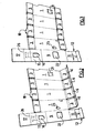
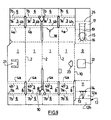
- the corrugated cardboard blank shown in Figure 1 includes four identical rectangular panels, 1, hinged together according to their longitudinal edges by parallel upsets 2, allowing fold all the panels 1 perpendicular to each other others around a bottle not shown.
- a first part 3 At each end of the panels is pivotally mounted a first part 3, around two parallel Upset 4, 4b, perpendicular to Upset 2.
- first sections 3 are extended by a second flap 6 hinged to the previous one by two parallel Upset 7, 7b, perpendicular to the lines 2 and separated by a narrow strip.
- the second flaps 6 are folded against the first associated shutters 3, the shutters 3 then being folded down against the face of the panels 1 not turned towards the inside of the sheath formed by these panels, to pinch the shutters 6 between the shutters 3 and the panels 1.
- the shutters 6 and folded associated with a panel 1 are articulated on the adjacent flaps 6 and they are thus maintained mutually in position, because of the elasticity of corrugated cardboard, without no locking system.
- the flaps 6 are of preferably articulated together by fold lines arranged in the extension of the upsets 2, while the adjacent shutters 3 are separated by cutouts 8, to facilitate the folding of the shutters.
- a fifth panel 9 is articulated on one of the panels 1 by a fold line 10 parallel to 2 and is straightened perpendicularly to this panel 1 for come to be applied against the inner face of a panel 1 contiguous to previous, in the mounted position of the sheath.
- a flap 11 is hinged by a transverse fold line perpendicular to Upset 2 and 10 and disposed substantially at the level of lines 4 a, 4 b, this flap 11 having such dimensions that after being straightened perpendicularly to 9 panel, it at least partially closes the sleeve at the bottom of the bottle to be packaged in this sleeve.
- a flap 12 is articulated by a transverse fold line, that is to say perpendicular to the ups and downs 2, this flap 12 being intended to be engaged in the sleeve by the corresponding end thereof to come to bear against the inner face of the panel 1 opposite the panel 5, in order to lock the flap 11 in transverse position.
- a transverse fold line that is to say perpendicular to the ups and downs 2
- this flap 12 being intended to be engaged in the sleeve by the corresponding end thereof to come to bear against the inner face of the panel 1 opposite the panel 5, in order to lock the flap 11 in transverse position.
- it can be divided into two parts 12 a, 12 b, by a folding line perpendicular to Upset 2.
- the portion 12a can comprise a cutting line 13 parallel to Upset 2, while cut line 14 is formed in the central portion of upsetting by which the flap 11 and the portion 12 has are articulated between them. Obliquely arranged ups and downs furthermore bring together the ends of the cutting lines 13 and 14, all this to provide the flap 12 with a possibility of deformation in order to adapt to bottoms of bottles of different diameters.
- a flap 15 having a cutout 16 intended to receive the neck of the bottle packaged in the sheath is articulated by a fold line perpendicular to the upsetting 2, to straighten the flap 15 transversely to the inside of the sheath.
- a flap 17 articulated on the flap 15 by a fold line perpendicular to the upsets 2 comes to apply inside the sleeve against the inner face of the panel 1 opposite the panel 9, in to lock the flap 15 in a position perpendicular to the panel 9.
- This flap itself abuts against a tongue 18 protruding inside the sleeve from panel 1 opposite the panel 9.
- cutting lines starting from the cutout 6 and diverging towards the outside of it allow it to adapt to bottle necks of different diameters.
- the flap 17 may optionally include a transverse fold line 26 delimiting at its end a portion of dimensions substantially equal to those of the internal section of the sheath, so as to straighten this end portion perpendicular to the portion of the flap 17 applied against the flap 1, to close the corresponding end of the sheath.
- Part of the shutter 17 closing the sheath can be locked by any known means in the art, for example by a tongue of the same type as the tongue 18, protruding inwardly from the sheath from panel 1 opposite to that against which is applied the panel 9 and under which will come to engage the free end of the end part folded shutter 17.
- a tear strip 20 (see FIG. extend transversely on the panels 1.
- a tab 21, here in T-shape is cut in the panel 1 against which is applied the panel 9 and articulated on this panel 1 by a fold line parallel to the upsets 2, so that it can be folded towards the inside of the sheath through a cutout 22 formed in position corresponding in the panel 9.
- This lug 21 is then engaged by folding or warping it into a cutout 23 of smaller dimensions, to protrude outwardly from the sheath and thus be locked in position.
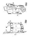
- the shutters 6 adjacent to the shutters 3 are first folded against these shutters 3, which are themselves folded towards the panels 1.
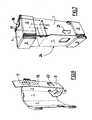
- the panels 1 are then folded in order to be brought perpendicular to each other, while simultaneously the panel 9 is brought against the adjacent panel 1 to which it is not adjacent, that the shutters 11 and 12 are brought into their position inside the sheath, as well as flaps 15 and 17 ( Figures 4 to 7).
- the tab 21 is then folded, first towards the inside of the sheath through the cutout 22 of the panel 9, then outward, through the cutout 23 of the panel 1 from which it comes, to lock the sleeve in assembled position (Figure 7).
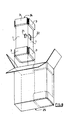
- FIGS. 9 and 10 In the embodiment variant of the sheath according to the invention illustrated by FIGS. 9 and 10, on which the elements already described are designated by the same reference figures, a body of locking shutters 3 and 6 in the folded position against the panel 1 partner is planned.
- This locking member 30 has the shape of an arrow, whose stem is articulated by a fold line, at its end furthest from the tip, on two contiguous panels 6, while the tip is disposed in the starting blank between the two flaps 3 associated with these flaps 6 and is directed to the cutout 8, which separates these flaps 3 and extends between the associated panels 1.
Landscapes
- Engineering & Computer Science (AREA)
- Mechanical Engineering (AREA)
- Cartons (AREA)
- Packaging Of Annular Or Rod-Shaped Articles, Wearing Apparel, Cassettes, Or The Like (AREA)
- Buffer Packaging (AREA)
- Packages (AREA)
- Wrappers (AREA)
Abstract
Description
La présente invention concerne un fourreau en un matériau semi-rigide tel que le carton ou le carton ondulé pour la protection et le calage d'un objet oblong, notamment d'une bouteille, à l'intérieur d'un conditionnement. L'invention concerne également un flan prédécoupé et refoulé, en un matériau semi-rigide, pour la réalisation de ce fourreau.The present invention relates to a sheath made of a semi-rigid material such as cardboard or corrugated cardboard for the protection and wedging an oblong object, in particular a bottle, inside a conditioning. The invention also relates to a pre-cut blank and repressed, a semi-rigid material for the realization of this sheath.
Il est fréquent de loger dans un conditionnement en carton, en carton ondulé ou similaire, une unique bouteille, qui est ensuite acheminée dans ce conditionnement jusqu'à son destinataire ou jusqu'à un lieu d'exposition en vente.It is common to stay in cardboard packaging, corrugated board or the like, a single bottle, which is then conveyed in that package to the addressee or up to an exhibition space for sale.
En cours de transport et de manutention, la bouteille doit être protégée contre les chocs extérieurs que reçoit l'emballage. Elle doit, en outre, être parfaitement calée à l'intérieur de celui-ci.During transport and handling, the bottle must be protected against external shocks received by the packaging. It must, in besides, be perfectly wedged inside of it.
En vue de répondre à ces exigences, la Demanderesse a déjà proposé, dans sa demande de brevet français FR-A-2 719 563, un dispositif en un matériau semi-rigide, tel que le carton ou le carton ondulé, pour la protection et le calage d'une bouteille à l'intérieur d'un conditionnement, ce dispositif comprenant quatre panneaux sensiblement rectangulaires, attenants entre eux par des refoulages longitudinaux sensiblement parallèles, de manière à pouvoir être repliés autour de la bouteille, en contact avec celle-ci, pour former un fourreau de protection de cette bouteille, ce dispositif étant caractérisé en ce qu'il comporte, à chaque extrémité de chacun desdits panneaux, un premier volet attenant au panneau associé par au moins une ligne de pliage transversale sensiblement perpendiculaire aux lignes de pliage longitudinales, ce premier volet pouvant être ainsi rabattu contre la face externe du panneau attenant non tournée vers la bouteille, pour former une surépaisseur à l'extérieur de ce panneau et éviter ainsi un contact direct entre ce panneau et le conditionnement.In order to meet these requirements, the Applicant has already proposed in its French patent application FR-A-2 719 563, a device made of a semi-rigid material, such as cardboard or cardboard corrugated, for the protection and setting of a bottle inside a conditioning, this device comprising four panels substantially rectangular, adjoining each other by upsetting longitudinally substantially parallel, so that they can be folded around the bottle, in contact with it, to form a sheath protection of this bottle, this device being characterized in that comprises, at each end of each of said panels, a first flap adjoining the panel associated with at least one fold line transverse substantially perpendicular to the fold lines longitudinal, this first component can be folded against the face external panel adjoining not facing the bottle, to form an extra thickness on the outside of this panel and thus avoid contact direct between this panel and the packaging.
En prévoyant un volet articulé à chaque extrémité des panneaux du dispositif et en le repliant contre la face externe de ce panneau, c'est-à-dire contre la face non tournée vers la bouteille logée dans le fourreau constitué par ces panneaux, on cale ainsi parfaitement la bouteille et son fourreau dans le conditionnement associé et l'on évite toute transmission directe à la bouteille ou aux panneaux en contact avec elle des chocs reçus par le conditionnement durant les opérations de transport ou de manutention.By providing an articulated flap at each end of the panels of the device and folding it against the outer face of this panel, that is to say against the non-facing side of the bottle housed in the sheath made up of these panels, we thus perfectly bottle and its sheath in the associated packaging and avoids any direct transmission to the bottle or to the panels in contact with it shocks received by the packaging during operations transportation or handling.
Dans ce dispositif, les volets disposés aux extrémités des panneaux peuvent être attenants entre eux latéralement par des lignes de pliage disposées dans le prolongement de celles par lesquelles les panneaux sont attenants entre eux.In this device, the flaps arranged at the ends of the panels can be attached to each other laterally by fold lines arranged in the extension of those by which the panels are adjoining each other.
Dans une forme de réalisation préférée décrite dans FR-A-2 719 563, le premier volet attenant à chacune des extrémités des panneaux est prolongé par un second volet, attenant à ce premier volet par au moins une ligne de pliage perpendiculaire aux lignes de pliage longitudinales entre panneaux, de manière à pouvoir être replié et pincé entre le premier volet associé et la face externe du panneau correspondant.In a preferred embodiment described in FR-A-2 719 563, the first component attached to each end of the panels is extended by a second component, adjacent to this first component by at least one fold line perpendicular to the fold lines longitudinal between panels, so that it can be folded and pinched between the first associated flap and the outer face of the panel corresponding.
Dans cette forme de réalisation, on accroít ainsi la surépaisseur constituée par les deux volets superposés, à chaque extrémité des panneaux, avec pour conséquence un meilleur calage du fourreau constitué par ces panneaux et une meilleure protection de la bouteille logée dans ce fourreau.In this embodiment, the extra thickness is thus increased. constituted by the two overlapping wings, at each end of panels, resulting in a better fit of the scabbard constituted by these panels and better protection of the bottle housed in this sheath.
Les seconds volets peuvent être attenants latéralement entre eux par des lignes de pliage disposées dans le prolongement de celles par lesquelles les panneaux sont attenants entre eux, tandis que, pour faciliter la mise en forme du dispositif, une découpe peut avantageusement séparer latéralement les premiers volets contigus.The second flaps can be sideways to each other by folding lines arranged in the extension of those by which the panels are adjacent to each other, whereas for facilitate the shaping of the device, a cut can advantageously laterally separate the first contiguous flaps.
En poursuivant ses études sur ce type de fourreau, la Demanderesse lui a ensuite apporté divers perfectionnements, visant notamment à :
- verrouiller le fourreau en position montée, alors que le fourreau précédemment décrit est dépourvu de tout moyen de verrouillage ;
- ménager à une extrémité du fourreau un moyen apte à s'opposer au passage de la bouteille qu'il contient, lorsque ce fourreau est manipulé en position verticale, pour être introduit verticalement dans un conditionnement ouvert vers le haut, alors que le fourreau précédemment décrit était disposé à l'horizontale dans son conditionnement.
- lock the sheath in mounted position, while the sleeve described above is devoid of any locking means;
- to provide at one end of the sheath means adapted to oppose the passage of the bottle that it contains, when the sheath is manipulated in a vertical position, to be introduced vertically into an upwardly open package, whereas the sheath previously described was arranged horizontally in its packaging.
A cet effet, dans sa demande de brevet français N°03.13231, déposée le 12 Novembre 2003 et non publiée à la date de dépôt de la présente demande, elle a décrit un fourreau du type général décrit ci-dessus, destiné à envelopper un objet oblong tel qu'une bouteille, ce fourreau étant caractérisé en ce qu'il comprend un moyen de verrouillage en position montée faisant corps avec au moins l'un desdits panneaux.For this purpose, in his French patent application No. 03.13231, filed on November 12, 2003 and not published on the filing date of the present application, it has described a sheath of the general type described above, intended to envelop an oblong object such as a bottle, this sleeve being characterized in that it comprises a means of locking in mounted position forming a body with at least one of said panels.
Ce moyen de verrouillage peut être de tout type connu en soi, mais, dans une forme de réalisation particulièrement simple, au moins une patte est découpée dans un premier panneau du fourreau comportant un bord longitudinal libre, tandis que, dans un panneau contigu au précédent et comportant également un bord longitudinal libre, est ménagée au moins une découpe destinée à recevoir la patte du premier panneau repliée vers l'intérieur du fourreau contre la face du panneau auquel elle est attenante, la forme et les dimensions de la découpe étant telles que la patte associée ne puisse y être engagée qu'après avoir été gauchie ou autrement déformée, la patte reprenant ensuite sa forme initiale du fait de l'élasticité relative du carton, pour être ainsi verrouillée en position par la découpe.This locking means can be of any type known per se, but, in a particularly simple embodiment, at least one leg is cut in a first panel of the sheath comprising a free longitudinal edge, while in a panel contiguous to the preceding and also having a free longitudinal edge, is provided at least one cutout intended to receive the leg of the first panel folded towards the inside of the sleeve against the face of the panel to which it is attached, the shape and dimensions of the cut being such that the associated leg can only be engaged after having been warped or otherwise distorted, the paw then taking its shape because of the relative elasticity of the carton, to be locked in position by the cut.
La patte et la découpe peuvent avoir par exemple la forme générale d'un T, et la patte peut notamment être articulée sur le panneau dont elle est issue par un refoulage parallèle à ceux par lesquels les panneaux sont articulés entre eux.The tab and the cutout may have for example the general shape of a T , and the tab may in particular be hinged to the panel from which it is derived by a push parallel to those by which the panels are hinged together.
Ce mode de verrouillage est particulièrement avantageux, puisque la patte et la découpe destinée à la recevoir sont ménagées dans des panneaux du fourreau et ne consomment donc aucune quantité additionnelle de matériau semi-rigide.This mode of locking is particularly advantageous, since the leg and the cut-out intended to receive it are arranged in sheath panels and therefore do not consume any quantity additional semi-rigid material.
En outre, la patte peut être déformée manuellement pour être introduite dans la découpe et le verrouillage du fourreau est donc particulièrement facile à mettre en oeuvre.In addition, the tab can be manually deformed to be introduced into the cut and the locking of the sheath is therefore particularly easy to implement.
La présente invention concerne un fourreau du même type général, mais équipé de volets aptes à obturer les extrémités du fourreau correspondant au fond et au col de la bouteille.The present invention relates to a sheath of the same general type, but equipped with shutters able to close the ends of the sheath corresponding to the bottom and neck of the bottle.
L'invention vise également à prévoir dans l'un de ces volets un moyen de calage en position du col de la bouteille.The invention also aims to provide in one of these components a setting means in position of the neck of the bottle.
L'invention vise enfin à proposer un fourreau de ce type apte à s'adapter à des bouteilles dont le corps et/ou le col ont des diamètres différents.The invention finally aims to propose a sheath of this type suitable for adapt to bottles whose body and / or neck have diameters different.
A cet effet, l'invention a pour objet un fourreau en un matériau semi-rigide tel que le carton ou le carton ondulé du type général décrit ci-dessus, pour la protection et le calage d'un objet oblong, notamment d'une bouteille, à l'intérieur d'un conditionnement, caractérisé en ce qu'il comporte un cinquième panneau attenant à l'un des quatre autres panneaux par une ligne de pliage parallèle à celles par lesquelles ces panneaux sont articulés entre eux, ce cinquième panneau venant s'appliquer contre la face interne de l'un des quatre panneaux disposé perpendiculairement à celui auquel ce cinquième panneau est attenant, ce cinquième panneau comportant :
- à une extrémité correspondant au fond de l'objet oblong à conditionner dans le fourreau, un volet articulé par une ligne de pliage transversale sur ce cinquième panneau et redressé perpendiculairement à celui-ci, afin d'obturer transversalement l'extrémité correspondante du fourreau, un moyen usuel de verrouillage étant prévu pour maintenir ce volet en position redressée ;
- à l'autre extrémité de ce cinquième panneau un volet articulé sur celui-ci par une ligne de pliage transversale et redressé perpendiculairement au panneau attenant à l'intérieur du fourreau, ce volet comportant une découpe ou des amorces d'une découpe destinée à recevoir une partie en saillie de l'objet oblong conditionné, notamment le col d'une bouteille, un second volet articulé sur le précédent par une ligne de pliage étant appliqué contre la face interne du panneau opposé au cinquième panneau.
- at one end corresponding to the bottom of the oblong object to be conditioned in the sheath, a flap hinged by a transverse fold line on this fifth panel and straightened perpendicular thereto, in order to seal transversely the corresponding end of the sheath, common locking means being provided to maintain this flap in the rectified position;
- at the other end of this fifth panel a flap hinged thereto by a transverse fold line and straightened perpendicular to the panel adjoining the inside of the sheath, this flap comprising a cutout or primers of a cutout intended to receive a protruding portion of the oblong conditioned object, in particular the neck of a bottle, a second flap hinged on the preceding by a fold line being applied against the inner face of the panel opposite the fifth panel.
En variante, le volet destiné à être appliqué contre la face interne du panneau opposé au cinquième panneau peut comporter un refoulage transversal, permettant de redresser l'extrémité de ce volet perpendiculairement aux différents panneaux, de manière à obturer l'extrémité correspondante du fourreau.Alternatively, the flap intended to be applied against the inner face opposite panel to the fifth panel may have a transversal upset, to straighten the end of this component perpendicular to the different panels, so as to close the corresponding end of the sheath.
Pour maintenir en position le volet obturant transversalement le fourreau à une extrémité, on peut prévoir un volet supplémentaire articulé sur celui-ci par une ligne de pliage transversale et venant s'appliquer contre la face interne du panneau opposé. Dans ce volet supplémentaire peuvent être ménagées une ou des coupes rejoignant la ligne de pliage par laquelle il est articulé sur le volet attenant, cette ligne de pliage pouvant aussi comporter une ligne de coupe afin de permettre à ce volet de se déformer, pour s'adapter au diamètre du fond de l'objet oblong conditionné.To maintain in position the shutter closing transversely sheath at one end, one can provide an additional flap articulated on it by a transverse fold line and coming apply against the inner face of the opposite panel. In this pane may be cut one or more sections joining the folding line by which it is articulated on the attached flap, this fold line which may also include a cut line in order to allow this component to deform, to adapt to the diameter of the bottom of the oblong conditioned object.
A l'extrémité opposée du fourreau, le volet attenant à celui dans lequel est ménagée une découpe et qui est appliqué contre la face interne d'un panneau opposé du fourreau pourra avantageusement être bloqué en position par une languette faisant saillie perpendiculairement à partir de ce panneau vers l'intérieur du fourreau.At the opposite end of the scabbard, the flap adjoining the one which is cut out and which is applied against the face internal part of an opposite panel of the sheath can advantageously be locked in position by a tongue protruding perpendicularly from this panel towards the inside of the sheath.
Pour maintenir le fourreau en position assemblée, un organe de verrouillage, notamment une languette, peut avantageusement être découpé dans le panneau contre une face interne duquel est appliqué le cinquième panneau et être articulé sur celui dont il est issu par une ligne de pliage parallèle à celles par lesquelles les panneaux sont articulés entre eux, de manière à pouvoir être replié vers l'intérieur du fourreau à travers une découpe ménagée dans le cinquième panneau et à être engagé après gauchissement ou pliage dans une découpe de dimensions plus faibles ménagée dans le panneau attenant au cinquième panneau, pour faire saillie vers l'extérieur du fourreau.To keep the sheath in the assembled position, an organ of locking, in particular a tongue, can advantageously be cut in the panel against an inner face of which is applied the fifth panel and be articulated on the one from which it is derived by a folding line parallel to those by which the panels are articulated together, so that they can be folded towards the inside of the sheath through a cutout formed in the fifth panel and to be engaged after warping or folding in a cutout of smaller dimensions in the panel adjacent to the fifth panel, to protrude outwardly of the sheath.
Le flan prédécoupé et refoulé en un matériau semi-rigide tel que le carton ou le carton ondulé dont est issu le fourreau conforme à l'invention constitue un autre objet de cette invention.The pre-cut and repressed blank made of a semi-rigid material such as the cardboard or corrugated cardboard from which the sheath conforming to the invention constitutes another object of this invention.
D'autres caractéristiques et avantages de l'invention ressortiront
de la description qui va suivre d'une forme de réalisation de celle-ci.
Dans cette description, on se référera aux dessins annexés, sur
lesquels :
Comme décrit dans la technique antérieure évoquée ci-dessus, le
flan de carton ondulé représenté sur la figure 1 comprend quatre
panneaux rectangulaires identiques, 1, articulés entre eux suivant leurs
bords longitudinaux par des refoulages parallèles 2, permettant de
replier l'ensemble des panneaux 1 perpendiculairement les uns aux
autres autour d'une bouteille non représentée.As described in the prior art mentioned above, the
corrugated cardboard blank shown in Figure 1 includes four
identical rectangular panels, 1, hinged together according to their
longitudinal edges by parallel upsets 2, allowing
fold all the
A chaque extrémité des panneaux est monté pivotant un premier
volet 3, autour de deux refoulages parallèles 4a, 4b, perpendiculaires
aux refoulages 2. On pourrait utiliser un unique refoulage, mais, en en
utilisant deux, séparés par une étroite bande, il est possible, de façon
connue en soi, de tenir compte de l'épaisseur du carton ondulé.At each end of the panels is pivotally mounted a
De façon analogue, les premiers volets 3 se prolongent par un
second volet 6, articulé sur le précédent par deux refoulages parallèles
7a, 7b, perpendiculaires aux lignes 2 et séparés par une étroite bande.Similarly, the
Comme on le voit sur la figure 1, les seconds volets 6 sont repliés
contre les premiers volets 3 associés, les volets 3 étant ensuite rabattus
contre la face des panneaux 1 non tournée vers l'intérieur du fourreau
formé par ces panneaux, pour pincer ainsi les volets 6 entre les volets 3
et les panneaux 1. Les volets 6 ainsi repliés associés à un panneau 1
sont articulés sur les volets 6 contigus et ils se maintiennent ainsi
mutuellement en position, du fait de l'élasticité du carton ondulé, sans
aucun système de verrouillage.As seen in Figure 1, the
Dans la forme de réalisation représentée, les volets 6 sont de
préférence articulés entre eux par des lignes de pliage disposées dans le
prolongement des refoulages 2, tandis que les volets 3 contigus sont
séparés par des découpes 8, destinées à faciliter le pliage des volets.In the embodiment shown, the
Conformément à l'invention, un cinquième panneau 9 est articulé
sur l'un des panneaux 1 par une ligne de pliage 10 parallèle aux
refoulages 2 et est redressé perpendiculairement à ce panneau 1 pour
venir s'appliquer contre la face interne d'un panneau 1 contigu au
précédent, en position montée du fourreau.According to the invention, a
Sur ce panneau 9, un volet 11 est articulé par une ligne de pliage
transversale perpendiculaire aux refoulages 2 et 10 et disposée
sensiblement au niveau des lignes 4a, 4b, ce volet 11 ayant des
dimensions telles qu'après avoir été redressé perpendiculairement au
panneau 9, il obture au moins partiellement le fourreau au niveau du
fond de la bouteille destinée à être conditionnée dans ce fourreau. On this
Sur le volet 11, un volet 12 est articulé par une ligne de pliage
transversale, c'est-à-dire perpendiculaire aux refoulages 2, ce volet 12
étant destiné à être engagé dans le fourreau par l'extrémité
correspondante de celui-ci pour venir s'appliquer contre la face interne
du panneau 1 opposé au panneau 5, afin de verrouiller le volet 11 en
position transversale. Afin de faciliter l'introduction du volet 12 dans le
fourreau, il peut être divisé en deux parties 12a, 12b, par une ligne de
pliage perpendiculaire aux refoulages 2.On the
Comme on le voit sur la figure 1, la partie 12a peut comporter une
ligne de coupe 13 parallèle aux refoulages 2, tandis qu'une ligne de
coupe 14 est ménagée dans la portion centrale du refoulage par lequel
le volet 11 et la partie 12a sont articulés entre eux. Des refoulages
disposés obliquement réunissent en outre les extrémités des lignes de
coupe 13 et 14, tout ceci pour offrir au volet 12a une possibilité de
déformation en vue de s'adapter à des fonds de bouteilles de diamètres
différents.As seen in Figure 1, the
A l'autre extrémité du panneau 9, un volet 15 comportant une
découpe 16 destinée à recevoir le col de la bouteille conditionnée dans le
fourreau est articulé par une ligne de pliage perpendiculaire aux
refoulages 2, permettant de redresser le volet 15 transversalement à
l'intérieur du fourreau.At the other end of the
Un volet 17, articulé sur le volet 15 par une ligne de pliage
perpendiculaire aux refoulages 2, vient s'appliquer à l'intérieur du
fourreau contre la face interne du panneau 1 opposé au panneau 9, en
vue de verrouiller le volet 15 en position perpendiculaire au panneau 9.
Ce volet vient lui-même en butée contre une languette 18 faisant saillie
vers l'intérieur du fourreau à partir du panneau 1 opposé au panneau
9. On pourrait, bien entendu, utiliser un autre moyen de blocage du
volet 17, issu de celui-ci ou du panneau 1 opposé au panneau 9, pour
le maintenir en position redressée.A
On notera que des lignes de coupe partant de la découpe 6 et
divergeant vers l'extérieur de celle-ci lui permettent de s'adapter à des
cols de bouteille de diamètres différents.It will be noted that cutting lines starting from the
Comme représenté, le volet 17 peut comporter éventuellement une
ligne de pliage transversale 26, délimitant à son extrémité une partie de
dimensions sensiblement égales à celles de la section interne du
fourreau, de manière à pouvoir redresser cette partie d'extrémité
perpendiculairement à la partie du volet 17 appliquée contre le volet 1,
pour obturer l'extrémité correspondante du fourreau. La partie du volet
17 obturant le fourreau pourra être verrouillé par tout moyen connu
dans la technique, par exemple par une languette du même type que la
languette 18 , faisant saillie vers l'intérieur du fourreau à partir du
panneau 1 opposé à celui contre lequel est appliqué le panneau 9 et
sous laquelle viendra s'engager l'extrémité libre de la partie d'extrémité
repliée du volet 17.As shown, the
Une bande d'arrachage 20 (voir figure 1) peut éventuellement
s'étendre transversalement sur les panneaux 1.A tear strip 20 (see FIG.
extend transversely on the
Pour verrouiller le fourreau en position montée, une patte 21, ici en
forme de T, est découpée dans le panneau 1 contre lequel est appliqué
le panneau 9 et articulée sur ce panneau 1 par une ligne de pliage
parallèle aux refoulages 2, de manière à pouvoir être repliée vers
l'intérieur du fourreau à travers une découpe 22 ménagée en position
correspondante dans le panneau 9. Cette patte 21 est ensuite engagée
par pliage ou en la gauchissant dans une découpe 23 de plus petites
dimensions, pour faire saillie vers l'extérieur du fourreau et être ainsi
verrouillée en position.To lock the sheath in the mounted position, a
La mise en forme du fourreau va maintenant être exposée brièvement en référence aux figures 2 à 7.The shaping of the sheath will now be exposed briefly with reference to Figures 2 to 7.
Les volets 6 attenants aux volets 3 sont d'abord repliés contre ces
volets 3, qui sont eux mêmes rabattus en direction des panneaux 1.The
Les panneaux 1 sont ensuite repliés afin d'être amenés
perpendiculairement les uns aux autres, tandis que, simultanément, le
panneau 9 est amené contre le panneau 1 contigu auquel il n'est pas
attenant, que les volets 11 et 12 sont amenés dans leur position
définitive à l'intérieur du fourreau, de même que les volets 15 et 17
(figures 4 à 7).The
La patte 21 est ensuite repliée, d'abord vers l'intérieur du fourreau
à travers la découpe 22 du panneau 9, puis vers l'extérieur, à travers la
découpe 23 du panneau 1 dont elle est issue, pour verrouiller le
fourreau en position assemblée (figure 7).The
Comme on le voit sur la figure 8, on peut introduire aisément le
fourreau 24, maintenu verticalement dans un conditionnement 25
ouvert à sa partie supérieure, dans lequel il vient se loger en position
verticale, sans que la bouteille contenue dans ce fourreau risque de
s'échapper dans cette position.As can be seen in Figure 8, it is easy to introduce the
Le conditionnement illustré par la figure 8 n'est donné qu'à titre d'exemple et il peut être d'un type absolument quelconque et contenir une unique bouteille logée dans un fourreau conforme à l'invention ou une pluralité de bouteilles logées dans des fourreaux distincts.The conditioning illustrated in Figure 8 is given only example and it can be of absolutely any type and contain a single bottle housed in a sheath according to the invention or a plurality of bottles housed in separate sleeves.
Dans la variante de réalisation du fourreau conforme à l'invention
illustrée par les figures 9 et 10, sur lesquelles les organes déjà décrits
sont désignés par les mêmes chiffres de référence, un organe de
verrouillage des volets 3 et 6 en position rabattue contre le panneau 1
associé est prévu.In the embodiment variant of the sheath according to the invention
illustrated by FIGS. 9 and 10, on which the elements already described
are designated by the same reference figures, a body of
locking
Cet organe de verrouillage 30 a la forme d'une flèche, dont la tige
est articulée par une ligne de pliage, à son extrémité la plus éloignée de
la pointe, sur deux panneaux 6 contigus, tandis que la pointe est
disposée dans le flan de départ entre les deux volets 3 associés à ces
volets 6 et est dirigée vers la découpe 8, qui sépare ces volets 3 et se
prolonge entre les panneaux 1 associés.This locking
Lorsque l'on replie les volets 6 et 3 contre les panneaux 1, il est
ainsi possible d'engager la pointe de la flèche de l'organe de verrouillage
26 dans la découpe 8 correspondante, en fin de montage du fourreau,
en déformant dans ce but les parties latérales de la pointe, qui
reprennent ensuite leur forme, du fait de l'élasticité du carton, en
verrouillant ainsi les volets 3, 6 en position repliée.When folding the
Claims (12)
Applications Claiming Priority (2)
| Application Number | Priority Date | Filing Date | Title |
|---|---|---|---|
| FR0402398 | 2004-03-08 | ||
| FR0402398A FR2867159B1 (en) | 2004-03-08 | 2004-03-08 | SEMI-RIGID MATERIAL TOOL FOR PROTECTING AND LAYING AN OBLONG OBJECT WITHIN A PACKAGING |
Publications (2)
| Publication Number | Publication Date |
|---|---|
| EP1574441A1 true EP1574441A1 (en) | 2005-09-14 |
| EP1574441B1 EP1574441B1 (en) | 2008-01-23 |
Family
ID=34814559
Family Applications (1)
| Application Number | Title | Priority Date | Filing Date |
|---|---|---|---|
| EP04292943A Expired - Lifetime EP1574441B1 (en) | 2004-03-08 | 2004-12-10 | Sleeve of semi rigid material for protecting and locating an oblong article inside a package |
Country Status (6)
| Country | Link |
|---|---|
| EP (1) | EP1574441B1 (en) |
| AT (1) | ATE384670T1 (en) |
| DE (1) | DE602004011469T2 (en) |
| ES (1) | ES2301952T3 (en) |
| FR (1) | FR2867159B1 (en) |
| PT (1) | PT1574441E (en) |
Cited By (4)
| Publication number | Priority date | Publication date | Assignee | Title |
|---|---|---|---|---|
| USD885889S1 (en) | 2018-07-17 | 2020-06-02 | International Paper Company | Blank for shipper insert |
| USD904191S1 (en) | 2018-07-17 | 2020-12-08 | International Paper Company | Shipper insert |
| US10913567B2 (en) | 2018-07-17 | 2021-02-09 | International Paper Company | Shipping insert and blank for forming same |
| FR3113402A1 (en) * | 2020-08-13 | 2022-02-18 | Sas Maubrac | Device for protecting and wedging foldable bottles of adjustable diameter and associated packaging method |
Families Citing this family (1)
| Publication number | Priority date | Publication date | Assignee | Title |
|---|---|---|---|---|
| DE102011103570B3 (en) * | 2011-05-30 | 2012-10-25 | Frank Berrenbaum | Arrangement for applying heat-shrinkable tube on container, comprises holding element for holding container, particularly bottle, where holding element comprises receiving section for receiving container |
Citations (2)
| Publication number | Priority date | Publication date | Assignee | Title |
|---|---|---|---|---|
| GB338271A (en) * | 1929-09-18 | 1930-11-20 | Alexander Aitchison Brown | Improvements in internal fittings for cardboard boxes for containing electric lamps and like articles |
| FR2719563A1 (en) * | 1994-05-04 | 1995-11-10 | Socar | Retaining frame for bottle arranged inside package |
-
2004
- 2004-03-08 FR FR0402398A patent/FR2867159B1/en not_active Expired - Lifetime
- 2004-12-10 AT AT04292943T patent/ATE384670T1/en not_active IP Right Cessation
- 2004-12-10 PT PT04292943T patent/PT1574441E/en unknown
- 2004-12-10 EP EP04292943A patent/EP1574441B1/en not_active Expired - Lifetime
- 2004-12-10 DE DE602004011469T patent/DE602004011469T2/en not_active Expired - Fee Related
- 2004-12-10 ES ES04292943T patent/ES2301952T3/en not_active Expired - Lifetime
Patent Citations (2)
| Publication number | Priority date | Publication date | Assignee | Title |
|---|---|---|---|---|
| GB338271A (en) * | 1929-09-18 | 1930-11-20 | Alexander Aitchison Brown | Improvements in internal fittings for cardboard boxes for containing electric lamps and like articles |
| FR2719563A1 (en) * | 1994-05-04 | 1995-11-10 | Socar | Retaining frame for bottle arranged inside package |
Cited By (4)
| Publication number | Priority date | Publication date | Assignee | Title |
|---|---|---|---|---|
| USD885889S1 (en) | 2018-07-17 | 2020-06-02 | International Paper Company | Blank for shipper insert |
| USD904191S1 (en) | 2018-07-17 | 2020-12-08 | International Paper Company | Shipper insert |
| US10913567B2 (en) | 2018-07-17 | 2021-02-09 | International Paper Company | Shipping insert and blank for forming same |
| FR3113402A1 (en) * | 2020-08-13 | 2022-02-18 | Sas Maubrac | Device for protecting and wedging foldable bottles of adjustable diameter and associated packaging method |
Also Published As
| Publication number | Publication date |
|---|---|
| ES2301952T3 (en) | 2008-07-01 |
| DE602004011469D1 (en) | 2008-03-13 |
| EP1574441B1 (en) | 2008-01-23 |
| ATE384670T1 (en) | 2008-02-15 |
| FR2867159A1 (en) | 2005-09-09 |
| DE602004011469T2 (en) | 2009-01-15 |
| PT1574441E (en) | 2008-04-15 |
| FR2867159B1 (en) | 2006-06-02 |
Similar Documents
| Publication | Publication Date | Title |
|---|---|---|
| EP0443930B1 (en) | Package made of cardboard, corrugated cardboard or other conveniently cut and folded sheet material, with a reclosable cover provided with a handle, and corresponding blank or blanks | |
| EP0454506A1 (en) | Package made from cardboard, corrugated cardboard or other conveniently cut and folded sheet material, with an interengageable reclosable cover, and corresponding blank | |
| EP1574441B1 (en) | Sleeve of semi rigid material for protecting and locating an oblong article inside a package | |
| EP0904235B1 (en) | Method for producing a package with nesting lid from a blank | |
| WO2015040332A1 (en) | Blank of sheet material having centring tabs, box and method implementing such a blank | |
| FR2620110A1 (en) | Individual package for bottle or other object with a neck, and corresponding blank. | |
| FR2847228A1 (en) | Semi-rigid container for sending articles such as bottles by post comprises inner wedging sleeve(s) inside parallelpiped outer pack | |
| FR2686316A1 (en) | Package made of cardboard, corrugated cardboard or other sheet material, suitably cut out and folded, with a lid which can be re-closed by engagement, and corresponding blank or blanks | |
| EP1348635B1 (en) | Blank for package out of semi-rigid material comprising on one surface a heat shrinkable film | |
| EP0114771A2 (en) | Blank for making a package provided with a handle, and corresponding preformed package and package | |
| EP1600388A1 (en) | Protective and blocking sleeve of semi-rigid material for an oblong object in a package | |
| FR2915738A1 (en) | Rectangular parallelepiped package for conditioning e.g. bottle, has panel with internal divider inserts partly straightened based on angle with respect to walls such that inserts define compartments receiving conditioned object with walls | |
| EP3144238B1 (en) | Packaging and blank for packaging with improved opening device | |
| FR2613697A1 (en) | Package forming a display unit made of cardboard, corrugated cardboard or other sheet material, in particular for glasses, and corresponding blanks | |
| FR2658482A1 (en) | Package made of cardboard, corrugated cardboard or other sheet material, suitably cut out and folded, and having a lid provided with a handle and which is re-closable, and corresponding blank or blanks | |
| FR2854136A1 (en) | Article package, has film articulated on one part of flap by folding line, such that flap swivels and retracts under solicitation of flaps overlapping part, where film is solicited towards interior for freeing film from flap | |
| FR2719563A1 (en) | Retaining frame for bottle arranged inside package | |
| FR3023831A1 (en) | PACKING COVER IN SEMI-RIDING MATERIAL. | |
| FR2878828A1 (en) | Article packing e.g. American box, for e.g. exhibition site, has portions delimited relative to walls of respective inner and outer parts by incipient break lines extending between folding lines and between free edges of respective walls | |
| FR2537548A1 (en) | Cut-out blank for forming a box with an automatic bottom and a separate lid and its method of folding and pasting | |
| FR2892389A3 (en) | Semi-rigid material e.g. cardboard, package for packaging article, has longitudinal walls` portions, flaps including false bottom system and parts articulated by folding lines, where portions, walls and flaps form deformable parallelogram | |
| FR2870523A1 (en) | Semi-rigid portable packaging for e.g. bottles, has two stubs whose parts are connected on lateral walls to form transversal walls for packaging, and another parts folded against one of former parts contiguous to latter walls | |
| FR2668120A1 (en) | Single-piece package made of cardboard, corrugated cardboard or other sheet material suitably cut out and folded, with a re-closable lid equipped with a handle, and corresponding blank | |
| EP1228970B1 (en) | Open carton box with carton cover | |
| FR2977242A1 (en) | Triangular-based prism-shaped package for packing sandwich, has two triangular walls respectively formed by superimposition of three sets of flaps, where third set of flaps is positioned between first and second sets of flaps in use state |
Legal Events
| Date | Code | Title | Description |
|---|---|---|---|
| PUAI | Public reference made under article 153(3) epc to a published international application that has entered the european phase |
Free format text: ORIGINAL CODE: 0009012 |
|
| AK | Designated contracting states |
Kind code of ref document: A1 Designated state(s): AT BE BG CH CY CZ DE DK EE ES FI FR GB GR HU IE IS IT LI LT LU MC NL PL PT RO SE SI SK TR |
|
| AX | Request for extension of the european patent |
Extension state: AL BA HR LV MK YU |
|
| AKX | Designation fees paid | ||
| 17P | Request for examination filed |
Effective date: 20060110 |
|
| RBV | Designated contracting states (corrected) |
Designated state(s): AT BE BG CH CY CZ DE DK EE ES FI FR GB GR HU IE IS IT LI LT LU MC NL PL PT RO SE SI SK TR |
|
| REG | Reference to a national code |
Ref country code: DE Ref legal event code: 8566 |
|
| GRAP | Despatch of communication of intention to grant a patent |
Free format text: ORIGINAL CODE: EPIDOSNIGR1 |
|
| GRAS | Grant fee paid |
Free format text: ORIGINAL CODE: EPIDOSNIGR3 |
|
| RAP1 | Party data changed (applicant data changed or rights of an application transferred) |
Owner name: SMURFIT KAPPA FRANCE SAS |
|
| GRAA | (expected) grant |
Free format text: ORIGINAL CODE: 0009210 |
|
| AK | Designated contracting states |
Kind code of ref document: B1 Designated state(s): AT BE BG CH CY CZ DE DK EE ES FI FR GB GR HU IE IS IT LI LT LU MC NL PL PT RO SE SI SK TR |
|
| REG | Reference to a national code |
Ref country code: GB Ref legal event code: FG4D Free format text: NOT ENGLISH |
|
| REG | Reference to a national code |
Ref country code: CH Ref legal event code: EP |
|
| REG | Reference to a national code |
Ref country code: IE Ref legal event code: FG4D Free format text: LANGUAGE OF EP DOCUMENT: FRENCH |
|
| REF | Corresponds to: |
Ref document number: 602004011469 Country of ref document: DE Date of ref document: 20080313 Kind code of ref document: P |
|
| REG | Reference to a national code |
Ref country code: PT Ref legal event code: SC4A Free format text: AVAILABILITY OF NATIONAL TRANSLATION Effective date: 20080402 |
|
| GBT | Gb: translation of ep patent filed (gb section 77(6)(a)/1977) |
Effective date: 20080410 |
|
| REG | Reference to a national code |
Ref country code: ES Ref legal event code: FG2A Ref document number: 2301952 Country of ref document: ES Kind code of ref document: T3 |
|
| REG | Reference to a national code |
Ref country code: FR Ref legal event code: RT |
|
| PG25 | Lapsed in a contracting state [announced via postgrant information from national office to epo] |
Ref country code: FI Free format text: LAPSE BECAUSE OF FAILURE TO SUBMIT A TRANSLATION OF THE DESCRIPTION OR TO PAY THE FEE WITHIN THE PRESCRIBED TIME-LIMIT Effective date: 20080123 Ref country code: IS Free format text: LAPSE BECAUSE OF FAILURE TO SUBMIT A TRANSLATION OF THE DESCRIPTION OR TO PAY THE FEE WITHIN THE PRESCRIBED TIME-LIMIT Effective date: 20080523 |
|
| PG25 | Lapsed in a contracting state [announced via postgrant information from national office to epo] |
Ref country code: BG Free format text: LAPSE BECAUSE OF FAILURE TO SUBMIT A TRANSLATION OF THE DESCRIPTION OR TO PAY THE FEE WITHIN THE PRESCRIBED TIME-LIMIT Effective date: 20080423 Ref country code: AT Free format text: LAPSE BECAUSE OF FAILURE TO SUBMIT A TRANSLATION OF THE DESCRIPTION OR TO PAY THE FEE WITHIN THE PRESCRIBED TIME-LIMIT Effective date: 20080123 |
|
| PG25 | Lapsed in a contracting state [announced via postgrant information from national office to epo] |
Ref country code: PL Free format text: LAPSE BECAUSE OF FAILURE TO SUBMIT A TRANSLATION OF THE DESCRIPTION OR TO PAY THE FEE WITHIN THE PRESCRIBED TIME-LIMIT Effective date: 20080123 Ref country code: SI Free format text: LAPSE BECAUSE OF FAILURE TO SUBMIT A TRANSLATION OF THE DESCRIPTION OR TO PAY THE FEE WITHIN THE PRESCRIBED TIME-LIMIT Effective date: 20080123 |
|
| PG25 | Lapsed in a contracting state [announced via postgrant information from national office to epo] |
Ref country code: SK Free format text: LAPSE BECAUSE OF FAILURE TO SUBMIT A TRANSLATION OF THE DESCRIPTION OR TO PAY THE FEE WITHIN THE PRESCRIBED TIME-LIMIT Effective date: 20080123 Ref country code: SE Free format text: LAPSE BECAUSE OF FAILURE TO SUBMIT A TRANSLATION OF THE DESCRIPTION OR TO PAY THE FEE WITHIN THE PRESCRIBED TIME-LIMIT Effective date: 20080423 Ref country code: DK Free format text: LAPSE BECAUSE OF FAILURE TO SUBMIT A TRANSLATION OF THE DESCRIPTION OR TO PAY THE FEE WITHIN THE PRESCRIBED TIME-LIMIT Effective date: 20080123 Ref country code: CZ Free format text: LAPSE BECAUSE OF FAILURE TO SUBMIT A TRANSLATION OF THE DESCRIPTION OR TO PAY THE FEE WITHIN THE PRESCRIBED TIME-LIMIT Effective date: 20080123 |
|
| PG25 | Lapsed in a contracting state [announced via postgrant information from national office to epo] |
Ref country code: RO Free format text: LAPSE BECAUSE OF FAILURE TO SUBMIT A TRANSLATION OF THE DESCRIPTION OR TO PAY THE FEE WITHIN THE PRESCRIBED TIME-LIMIT Effective date: 20080123 |
|
| PLBE | No opposition filed within time limit |
Free format text: ORIGINAL CODE: 0009261 |
|
| STAA | Information on the status of an ep patent application or granted ep patent |
Free format text: STATUS: NO OPPOSITION FILED WITHIN TIME LIMIT |
|
| 26N | No opposition filed |
Effective date: 20081024 |
|
| PG25 | Lapsed in a contracting state [announced via postgrant information from national office to epo] |
Ref country code: LT Free format text: LAPSE BECAUSE OF FAILURE TO SUBMIT A TRANSLATION OF THE DESCRIPTION OR TO PAY THE FEE WITHIN THE PRESCRIBED TIME-LIMIT Effective date: 20080123 |
|
| PGFP | Annual fee paid to national office [announced via postgrant information from national office to epo] |
Ref country code: PT Payment date: 20081126 Year of fee payment: 5 |
|
| PG25 | Lapsed in a contracting state [announced via postgrant information from national office to epo] |
Ref country code: EE Free format text: LAPSE BECAUSE OF FAILURE TO SUBMIT A TRANSLATION OF THE DESCRIPTION OR TO PAY THE FEE WITHIN THE PRESCRIBED TIME-LIMIT Effective date: 20080123 |
|
| BERE | Be: lapsed |
Owner name: SMURFIT KAPPA FRANCE SAS Effective date: 20081231 |
|
| PG25 | Lapsed in a contracting state [announced via postgrant information from national office to epo] |
Ref country code: CY Free format text: LAPSE BECAUSE OF FAILURE TO SUBMIT A TRANSLATION OF THE DESCRIPTION OR TO PAY THE FEE WITHIN THE PRESCRIBED TIME-LIMIT Effective date: 20080123 Ref country code: MC Free format text: LAPSE BECAUSE OF NON-PAYMENT OF DUE FEES Effective date: 20081231 |
|
| REG | Reference to a national code |
Ref country code: CH Ref legal event code: PL |
|
| GBPC | Gb: european patent ceased through non-payment of renewal fee |
Effective date: 20081210 |
|
| NLV4 | Nl: lapsed or anulled due to non-payment of the annual fee |
Effective date: 20090701 |
|
| PG25 | Lapsed in a contracting state [announced via postgrant information from national office to epo] |
Ref country code: BE Free format text: LAPSE BECAUSE OF NON-PAYMENT OF DUE FEES Effective date: 20081231 |
|
| REG | Reference to a national code |
Ref country code: FR Ref legal event code: ST Effective date: 20090831 |
|
| PG25 | Lapsed in a contracting state [announced via postgrant information from national office to epo] |
Ref country code: DE Free format text: LAPSE BECAUSE OF NON-PAYMENT OF DUE FEES Effective date: 20090701 Ref country code: IE Free format text: LAPSE BECAUSE OF NON-PAYMENT OF DUE FEES Effective date: 20081210 Ref country code: LI Free format text: LAPSE BECAUSE OF NON-PAYMENT OF DUE FEES Effective date: 20081231 Ref country code: CH Free format text: LAPSE BECAUSE OF NON-PAYMENT OF DUE FEES Effective date: 20081231 |
|
| PG25 | Lapsed in a contracting state [announced via postgrant information from national office to epo] |
Ref country code: NL Free format text: LAPSE BECAUSE OF NON-PAYMENT OF DUE FEES Effective date: 20090701 Ref country code: GB Free format text: LAPSE BECAUSE OF NON-PAYMENT OF DUE FEES Effective date: 20081210 |
|
| REG | Reference to a national code |
Ref country code: ES Ref legal event code: FD2A Effective date: 20081211 |
|
| PG25 | Lapsed in a contracting state [announced via postgrant information from national office to epo] |
Ref country code: ES Free format text: LAPSE BECAUSE OF NON-PAYMENT OF DUE FEES Effective date: 20081211 Ref country code: FR Free format text: LAPSE BECAUSE OF NON-PAYMENT OF DUE FEES Effective date: 20081231 |
|
| REG | Reference to a national code |
Ref country code: PT Ref legal event code: MM4A Free format text: LAPSE DUE TO NON-PAYMENT OF FEES Effective date: 20100611 |
|
| PG25 | Lapsed in a contracting state [announced via postgrant information from national office to epo] |
Ref country code: PT Free format text: LAPSE BECAUSE OF NON-PAYMENT OF DUE FEES Effective date: 20100611 Ref country code: HU Free format text: LAPSE BECAUSE OF FAILURE TO SUBMIT A TRANSLATION OF THE DESCRIPTION OR TO PAY THE FEE WITHIN THE PRESCRIBED TIME-LIMIT Effective date: 20080724 Ref country code: LU Free format text: LAPSE BECAUSE OF NON-PAYMENT OF DUE FEES Effective date: 20081210 |
|
| PG25 | Lapsed in a contracting state [announced via postgrant information from national office to epo] |
Ref country code: TR Free format text: LAPSE BECAUSE OF FAILURE TO SUBMIT A TRANSLATION OF THE DESCRIPTION OR TO PAY THE FEE WITHIN THE PRESCRIBED TIME-LIMIT Effective date: 20080123 |
|
| PG25 | Lapsed in a contracting state [announced via postgrant information from national office to epo] |
Ref country code: GR Free format text: LAPSE BECAUSE OF FAILURE TO SUBMIT A TRANSLATION OF THE DESCRIPTION OR TO PAY THE FEE WITHIN THE PRESCRIBED TIME-LIMIT Effective date: 20080424 |
|
| PG25 | Lapsed in a contracting state [announced via postgrant information from national office to epo] |
Ref country code: IT Free format text: LAPSE BECAUSE OF NON-PAYMENT OF DUE FEES Effective date: 20081210 |