EP1574402B1 - Protège-genoux pour passagers d'un véhicule - Google Patents
Protège-genoux pour passagers d'un véhicule Download PDFInfo
- Publication number
- EP1574402B1 EP1574402B1 EP04029939A EP04029939A EP1574402B1 EP 1574402 B1 EP1574402 B1 EP 1574402B1 EP 04029939 A EP04029939 A EP 04029939A EP 04029939 A EP04029939 A EP 04029939A EP 1574402 B1 EP1574402 B1 EP 1574402B1
- Authority
- EP
- European Patent Office
- Prior art keywords
- knee
- outer shell
- inner shell
- knee protector
- protector according
- Prior art date
- Legal status (The legal status is an assumption and is not a legal conclusion. Google has not performed a legal analysis and makes no representation as to the accuracy of the status listed.)
- Expired - Lifetime
Links
Images
Classifications
-
- B—PERFORMING OPERATIONS; TRANSPORTING
- B60—VEHICLES IN GENERAL
- B60R—VEHICLES, VEHICLE FITTINGS, OR VEHICLE PARTS, NOT OTHERWISE PROVIDED FOR
- B60R21/00—Arrangements or fittings on vehicles for protecting or preventing injuries to occupants or pedestrians in case of accidents or other traffic risks
- B60R21/02—Occupant safety arrangements or fittings, e.g. crash pads
- B60R21/04—Padded linings for the vehicle interior ; Energy absorbing structures associated with padded or non-padded linings
- B60R21/045—Padded linings for the vehicle interior ; Energy absorbing structures associated with padded or non-padded linings associated with the instrument panel or dashboard
-
- B—PERFORMING OPERATIONS; TRANSPORTING
- B60—VEHICLES IN GENERAL
- B60R—VEHICLES, VEHICLE FITTINGS, OR VEHICLE PARTS, NOT OTHERWISE PROVIDED FOR
- B60R21/00—Arrangements or fittings on vehicles for protecting or preventing injuries to occupants or pedestrians in case of accidents or other traffic risks
- B60R2021/003—Arrangements or fittings on vehicles for protecting or preventing injuries to occupants or pedestrians in case of accidents or other traffic risks characterised by occupant or pedestian
- B60R2021/0039—Body parts of the occupant or pedestrian affected by the accident
- B60R2021/0051—Knees
Definitions
- the invention relates to a knee protection device for occupants of a motor vehicle according to the preamble of patent claim 1.
- a well-known knee protection device US 3,907,326 , the genus mentioned above is provided with a knee strike wall, which is held below an energy absorbing steering column means by means of a console in position.
- the knee impact wall has a support wall made of metal, which is followed by a foam pad.
- the foam pad is covered with a plastic cladding.
- a comparable solution is also the US 3,938,821 refer to.
- the DE 296 16 485 U1 deals with a safety device for a motor vehicle with a kneepad for occupants in the field of a dashboard in a passenger compartment of the motor vehicle.
- the knee-lengther has a knee lift panel with an extruded profile and a trim part for the latter, which extends adjacent to knees of the occupants and consists of a rigid plastic foam.
- the generic GB 2 339 174 A describes a foam-filled pad plate for a motor vehicle, for example a knee pad in the lower part of a glove box lid.
- the pad plate forms several filled with foam spaces.
- the US 5,577,770 describes an instrument panel with a knee protector for motor vehicles.
- This knee protector comprises two spaced-apart deformation straps and has a support part which acts as a load distributor for the knee forces.
- Part of this knee protection is also an energy-absorbing insert, for example made of foam.
- Foam-filled components for absorbing impact forces are known from US Pat US 2002/054977 A1 and from the US 4,786,540 known.
- the advantages achieved by the invention are to be seen in the fact that the inner shell, the outer shell and the foam pad are produced in a simple manner and can be joined together to form a unit. This is still going through the supported in cross-section U-shaped profile and the edge flange and the first Anschlenkabprungung and the second Anschlußabwinkelung. Finally, the knee impact wall and the deformation element with a corresponding configuration, ie when the deformation element perform a main deformation work and the knee impact wall perform a partial deformation work, enable a highly effective function or targeted protection for the occupants of the motor vehicle.
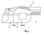
- a control panel 1 is installed in a passenger compartment 2 of a motor vehicle, not shown, and provided with a knee protection device 3 for occupants.
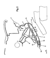
- the knee protection device 3 comprises a knee impact wall 4, which is arranged adjacent to knees 5 of the occupants - Fig. 2 - and a deformation element 6 covers.
- the deformation element 6 is formed, for example. Through an extruded profile 7 of a light metal alloy, which provides targeted protection for occupants by a defined arrangement of walls 8, webs 9 and cavities 10 in an accidental accident of the vehicle when they are moved forward in the direction of travel A. , In doing so, the deformation element 6 performs a main deformation work; the knee lift 4 a partial deformation work.
- the knee loading wall 4 has a first inner deformation element 6 facing the support surface 11, which extends with, for example, constant distance As to a second support surface 12 of the deformation element 6.
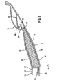
- the knee impact wall 4 is constructed in several parts and has an inner shell 13 and an outer shell 14 which define a cavity 15. In the cavity 15, a foam pad 16 is inserted, and the inner shell 13 and the outer shell 14 are connected to each other at first and second connection zones 17 and 18 by suitable means.
- the inner shell 13, the outer shell 14 and the foam pad 16 are made of plastic, wherein the strength of the inner shell 13 and the outer shell 14 is designed so that they have a defined stiffness, but in conjunction with the foam pad 16 a partial deformation work for the knee protection device. 3 Afford.
- At least the first connection zone 17 is provided with a cross-sectionally U-shaped profile 19 with legs 20 and 21, of which one leg 20 is aligned approximately to the plane of the support plane 11 performing inner shell wall 22 and connected thereto, whereas on the other leg 21st an edge flange 23 of the outer shell 14 abuts.
- the leg 21 and the edge flange 23 are joined together by gluing or other suitable method.
- first and second terminal bends 24 and 25 are provided between the inner shell 13 and the outer shell 14 in the region of the second connection zone 18 - FIG. The latter are connected to one another by means of one or more screws 26.
- the first terminal bend 24 is provided on the inner shell 22; second Anschlußabwinkelung 25 on the outer shell 14.
- the second Anschlußabwinkelung 25 is part of a hollow body 27 which is integrated into the outer shell 14 and the outer shell 14 in the region of the second connection zone 18 gives a defined stiffness.
Landscapes
- Engineering & Computer Science (AREA)
- Mechanical Engineering (AREA)
- Body Structure For Vehicles (AREA)
- Professional, Industrial, Or Sporting Protective Garments (AREA)
- Instrument Panels (AREA)
Claims (7)
- Dispositif de protection des genoux pour les passagers d'un véhicule automobile, qui est agencé dans la zone d'un tableau de bord (1) et comporte une paroi d'impact pour genoux (4) avec un rembourrage de mousse (16), laquelle paroi d'impact pour genoux (4) est située à proximité des genoux des passagers, ladite paroi d'impact pour genoux (4) comportant une coque intérieure (13) et une coque extérieure (14), qui délimitent une cavité (15) et qui sont réunies au niveau de zones d'assemblage (17 et 18) et assemblées l'une à l'autre par des moyens appropriés, sachant qu'au moins une première zone d'assemblage (17) entre la coque intérieure (13) et la coque extérieure (14) est munie d'un profilé (19) à section en forme de U et avec deux branches (20 et 21), caractérisé en ce que la paroi d'impact pour genoux (4) masque un élément de déformation (6), de telle sorte que l'élément de déformation (6) fournit le travail de déformation principal et la paroi d'impact pour genoux (4) fournit un travail de déformation partiel, une première face d'appui (11) intérieure de la paroi d'impact pour genoux (4) étant située à distance (As) d'une deuxième face d'appui de l'élément de déformation (6), une branche (20) étant orientée sensiblement selon le plan d'une paroi de coque intérieure (22) formant la face d'appui (11) et étant reliée à ladite paroi, une collerette périphérique (23) de la coque extérieure(14) étant en appui contre l'autre branche (21).
- Dispositif de protection des genoux selon la revendication 1, caractérisé en ce que la branche (21) et la collerette périphérique (23) sont assemblées l'une à l'autre par collage.
- Dispositif de protection des genoux selon la revendication 1, caractérisé en ce qu'un premier coude de raccordement (24) et un deuxième coude de raccordement (25) sont réunis entre la coque intérieure (13) et la coque extérieure (14) dans la région de la deuxième zone d'assemblage (18).
- Dispositif de protection des genoux selon la revendication 3, caractérisé en ce que le premier coude de raccordement (24) et le deuxième coude de raccordement (25) sont assemblés l'un à l'autre au moyen de vis (26).
- Dispositif de protection des genoux selon la revendication 1, caractérisé en ce que le profilé (19) est prévu sur la coque intérieure (13) et la collerette périphérique (23) est prévue sur la coque extérieure (14).
- Dispositif de protection des genoux selon la revendication 3, caractérisé en ce que le premier coude de raccordement (24) est prévu sur la coque intérieure (13) et le deuxième coude de raccordement (25) est prévu sur la coque extérieure (14).
- Dispositif de protection des genoux selon la revendication 6, caractérisé en ce que le deuxième coude de raccordement (25) fait partie intégrante d'un corps creux (27) de la coque extérieure (14).
Applications Claiming Priority (2)
| Application Number | Priority Date | Filing Date | Title |
|---|---|---|---|
| DE102004011330 | 2004-03-09 | ||
| DE102004011330A DE102004011330B3 (de) | 2004-03-09 | 2004-03-09 | Knieschutzeinrichtung für Insassen eines Kraftfahrzeugs |
Publications (2)
| Publication Number | Publication Date |
|---|---|
| EP1574402A1 EP1574402A1 (fr) | 2005-09-14 |
| EP1574402B1 true EP1574402B1 (fr) | 2007-09-05 |
Family
ID=34813622
Family Applications (1)
| Application Number | Title | Priority Date | Filing Date |
|---|---|---|---|
| EP04029939A Expired - Lifetime EP1574402B1 (fr) | 2004-03-09 | 2004-12-17 | Protège-genoux pour passagers d'un véhicule |
Country Status (4)
| Country | Link |
|---|---|
| US (1) | US7334816B2 (fr) |
| EP (1) | EP1574402B1 (fr) |
| JP (1) | JP2005255159A (fr) |
| DE (2) | DE102004011330B3 (fr) |
Families Citing this family (7)
| Publication number | Priority date | Publication date | Assignee | Title |
|---|---|---|---|---|
| USD660210S1 (en) * | 2010-10-06 | 2012-05-22 | Toyota Jidosha Kabushiki Kaisha | Instrument panel for an automobile |
| USD656441S1 (en) * | 2010-12-22 | 2012-03-27 | Chrysler Group LLC. | Automobile interior |
| USD704608S1 (en) * | 2011-12-27 | 2014-05-13 | Toyota Jidosha Kabushiki Kaisha | Instrument panel |
| AU346985S (en) * | 2012-05-25 | 2013-02-15 | Honda Motor Co Ltd | An instrument panel for an automobile |
| USD704114S1 (en) * | 2012-12-26 | 2014-05-06 | Toyota Jidosha Kabushiki Kaisha | Instrument panel for an automobile |
| KR101673690B1 (ko) * | 2014-11-06 | 2016-11-07 | 현대자동차주식회사 | 차량용 니볼스터 장치 |
| KR101694024B1 (ko) | 2015-07-01 | 2017-01-06 | 현대자동차주식회사 | 차량의 무릎 보호 구조물 |
Family Cites Families (21)
| Publication number | Priority date | Publication date | Assignee | Title |
|---|---|---|---|---|
| US3907326A (en) * | 1972-07-28 | 1975-09-23 | Gen Motors Corp | Occupant knee restraint |
| US3938821A (en) * | 1973-10-10 | 1976-02-17 | General Motors Corporation | Occupant knee restraint |
| US3966227A (en) * | 1974-10-24 | 1976-06-29 | General Motors Corporation | Cover assembly for an occupant restraint system |
| DE3740687A1 (de) * | 1987-03-02 | 1988-09-15 | Daimler Benz Ag | Als blasformkoerper ausgebildeter stuetzkoerper |
| DE4105027C1 (fr) * | 1991-02-19 | 1992-04-16 | Mercedes-Benz Aktiengesellschaft, 7000 Stuttgart, De | |
| JP3169273B2 (ja) * | 1992-09-02 | 2001-05-21 | マツダ株式会社 | 自動車の乗員保護装置 |
| US5577770A (en) * | 1994-08-26 | 1996-11-26 | Mercedes-Benz Ag | Deformation bar for energy-absorbing support |
| DE19511512C2 (de) * | 1994-08-26 | 2002-03-21 | Daimler Chrysler Ag | Deformationsbügel zum energieabsorbierenden Abstützen |
| JPH08164811A (ja) * | 1994-12-14 | 1996-06-25 | Suzuki Motor Corp | ニーボルスターの構造 |
| DE29616485U1 (de) * | 1996-09-21 | 1996-11-28 | Adam Opel AG, 65428 Rüsselsheim | Sicherheitseinrichtung |
| DE19712662A1 (de) * | 1997-03-26 | 1998-10-08 | Daimler Benz Ag | Deformationselement in einem Kraftfahrzeug, insbesondere für eine Instrumententafel |
| DE19756334C2 (de) * | 1997-12-18 | 2000-04-20 | Daimler Chrysler Ag | Energieabsorbierendes Deformationsprofil für ein Kraftfahrzeug |
| GB9812944D0 (en) * | 1998-06-17 | 1998-08-12 | Rover Group | A bolster panel |
| DE20016717U1 (de) * | 2000-09-27 | 2001-02-15 | Trw Repa Gmbh | Seitengassackmodul |
| JP3488864B2 (ja) * | 2000-10-19 | 2004-01-19 | 森六株式会社 | 車両用衝撃吸収部材 |
| JP4590115B2 (ja) * | 2001-02-15 | 2010-12-01 | 森六テクノロジー株式会社 | 車両用衝撃吸収構造 |
| US6848708B2 (en) * | 2002-03-19 | 2005-02-01 | Autoliv Asp, Inc. | Inflatable curtain module for use in a vehicle |
| JP4196756B2 (ja) * | 2003-03-13 | 2008-12-17 | タカタ株式会社 | カーテンエアバッグのガイド機構及びカーテンエアバッグ装置 |
| US20050200103A1 (en) * | 2004-02-27 | 2005-09-15 | Burns Sean P. | Pyrotechnic linear inflator with structural enhancement |
| US7213836B2 (en) * | 2004-08-25 | 2007-05-08 | Key Safety Systems, Inc. | Curtain air bag module |
| US7625005B2 (en) * | 2005-08-30 | 2009-12-01 | Trw Vehicle Safety Systems Inc. | Collapsable inflatable curtain module |
-
2004
- 2004-03-09 DE DE102004011330A patent/DE102004011330B3/de not_active Expired - Fee Related
- 2004-12-17 EP EP04029939A patent/EP1574402B1/fr not_active Expired - Lifetime
- 2004-12-17 DE DE502004004872T patent/DE502004004872D1/de not_active Expired - Lifetime
-
2005
- 2005-03-08 US US11/073,577 patent/US7334816B2/en not_active Expired - Fee Related
- 2005-03-09 JP JP2005066229A patent/JP2005255159A/ja active Pending
Non-Patent Citations (1)
| Title |
|---|
| None * |
Also Published As
| Publication number | Publication date |
|---|---|
| US7334816B2 (en) | 2008-02-26 |
| US20050200110A1 (en) | 2005-09-15 |
| DE502004004872D1 (de) | 2007-10-18 |
| EP1574402A1 (fr) | 2005-09-14 |
| DE102004011330B3 (de) | 2005-09-01 |
| JP2005255159A (ja) | 2005-09-22 |
Similar Documents
| Publication | Publication Date | Title |
|---|---|---|
| EP1228948B1 (fr) | Traverse de support pour tableau de bord de véhicule | |
| EP2020342B1 (fr) | Tableau de distribution pour un véhicule automobile | |
| DE10146494C5 (de) | Kniestütze für Kraftfahrzeuge | |
| DE19544266B4 (de) | Energieabsorbierende Fahrzeugtür | |
| EP1981737B1 (fr) | Corps d absorption d énergie, dispositif de protection contre une collision, élément d habillage intérieur pour véhicule automobile et traverse | |
| EP0710578B1 (fr) | Elément d'habillage, en particulier panneau d'habillage pour une porte, pour un véhicule automobile | |
| EP1867559A2 (fr) | Élément de renfort pour dispositif de protection contre le choc | |
| DE10146495A1 (de) | Kniestütze für Insassen | |
| DE2644499A1 (de) | Sicherheitsarmaturenbrett | |
| DE202007016671U1 (de) | Energieabsorber zur Verwendung als Aufprallschutz in einem Kraftfahrzeug | |
| EP1574402B1 (fr) | Protège-genoux pour passagers d'un véhicule | |
| DE102004028513A1 (de) | Sicherheitseinrichtung für ein Fahrzeug, insbesondere für ein Kraftfahrzeug | |
| DE102004027100A1 (de) | Sicherheitsanordnung für den Innenraum eines Kraftfahrzeuges | |
| DE102004009665B4 (de) | A-Säule für eine Kraftfahrzeugkarosserie | |
| DE102004056148A1 (de) | Verbundbauteil und Verfahren zur Herstellung eines Verbundbauteils | |
| DE102011050932A1 (de) | Gassack für ein Fahrzeuginsassen-Rückhaltesystem und Verfahren zum Herstellen eines Gassacks | |
| EP1568566A2 (fr) | Volant pour véhicules automobile absorbant les chocs | |
| DE10223861A1 (de) | Karosseriehaube | |
| DE202017103910U1 (de) | Führerstandsystem | |
| DE602004003950T2 (de) | Armaturenbrett zur aufnahme der energie eines fahrers | |
| DE102005039125B3 (de) | Instrumententafelanordnung | |
| EP0945329B1 (fr) | Un élément d'absorption de choc | |
| DE10313730B4 (de) | Knie-Airbagmodul eines Kraftfahrzeuges | |
| DE102022120872B3 (de) | Instrumententafelträger | |
| DE10227406A1 (de) | Formhimmel für ein Fahrzeug, insbesondere für ein Kraftfahrzeug, sowie ein Verfahren zur Herstellung eines Formhimmels |
Legal Events
| Date | Code | Title | Description |
|---|---|---|---|
| PUAI | Public reference made under article 153(3) epc to a published international application that has entered the european phase |
Free format text: ORIGINAL CODE: 0009012 |
|
| AK | Designated contracting states |
Kind code of ref document: A1 Designated state(s): AT BE BG CH CY CZ DE DK EE ES FI FR GB GR HU IE IS IT LI LT LU MC NL PL PT RO SE SI SK TR |
|
| AX | Request for extension of the european patent |
Extension state: AL BA HR LV MK YU |
|
| 17P | Request for examination filed |
Effective date: 20060314 |
|
| AKX | Designation fees paid |
Designated state(s): DE FR GB IT |
|
| 17Q | First examination report despatched |
Effective date: 20061114 |
|
| GRAP | Despatch of communication of intention to grant a patent |
Free format text: ORIGINAL CODE: EPIDOSNIGR1 |
|
| GRAS | Grant fee paid |
Free format text: ORIGINAL CODE: EPIDOSNIGR3 |
|
| GRAA | (expected) grant |
Free format text: ORIGINAL CODE: 0009210 |
|
| AK | Designated contracting states |
Kind code of ref document: B1 Designated state(s): DE FR GB IT |
|
| REG | Reference to a national code |
Ref country code: GB Ref legal event code: FG4D Free format text: NOT ENGLISH |
|
| REF | Corresponds to: |
Ref document number: 502004004872 Country of ref document: DE Date of ref document: 20071018 Kind code of ref document: P |
|
| ET | Fr: translation filed | ||
| GBT | Gb: translation of ep patent filed (gb section 77(6)(a)/1977) |
Effective date: 20071212 |
|
| RAP2 | Party data changed (patent owner data changed or rights of a patent transferred) |
Owner name: DR. ING. H.C. F. PORSCHE AKTIENGESELLSCHAFT |
|
| PLBE | No opposition filed within time limit |
Free format text: ORIGINAL CODE: 0009261 |
|
| STAA | Information on the status of an ep patent application or granted ep patent |
Free format text: STATUS: NO OPPOSITION FILED WITHIN TIME LIMIT |
|
| RAP2 | Party data changed (patent owner data changed or rights of a patent transferred) |
Owner name: DR. ING. H.C. F. PORSCHE AKTIENGESELLSCHAFT |
|
| 26N | No opposition filed |
Effective date: 20080606 |
|
| REG | Reference to a national code |
Ref country code: FR Ref legal event code: TP |
|
| REG | Reference to a national code |
Ref country code: FR Ref legal event code: CD |
|
| REG | Reference to a national code |
Ref country code: FR Ref legal event code: TP |
|
| REG | Reference to a national code |
Ref country code: GB Ref legal event code: 732E Free format text: REGISTERED BETWEEN 20110310 AND 20110316 |
|
| REG | Reference to a national code |
Ref country code: GB Ref legal event code: 732E Free format text: REGISTERED BETWEEN 20110331 AND 20110406 |
|
| REG | Reference to a national code |
Ref country code: FR Ref legal event code: PLFP Year of fee payment: 12 |
|
| PGFP | Annual fee paid to national office [announced via postgrant information from national office to epo] |
Ref country code: GB Payment date: 20151221 Year of fee payment: 12 Ref country code: DE Payment date: 20151207 Year of fee payment: 12 |
|
| PGFP | Annual fee paid to national office [announced via postgrant information from national office to epo] |
Ref country code: FR Payment date: 20151221 Year of fee payment: 12 |
|
| PGFP | Annual fee paid to national office [announced via postgrant information from national office to epo] |
Ref country code: IT Payment date: 20151228 Year of fee payment: 12 |
|
| REG | Reference to a national code |
Ref country code: DE Ref legal event code: R119 Ref document number: 502004004872 Country of ref document: DE |
|
| GBPC | Gb: european patent ceased through non-payment of renewal fee |
Effective date: 20161217 |
|
| REG | Reference to a national code |
Ref country code: FR Ref legal event code: ST Effective date: 20170831 |
|
| PG25 | Lapsed in a contracting state [announced via postgrant information from national office to epo] |
Ref country code: FR Free format text: LAPSE BECAUSE OF NON-PAYMENT OF DUE FEES Effective date: 20170102 Ref country code: IT Free format text: LAPSE BECAUSE OF NON-PAYMENT OF DUE FEES Effective date: 20161217 |
|
| PG25 | Lapsed in a contracting state [announced via postgrant information from national office to epo] |
Ref country code: DE Free format text: LAPSE BECAUSE OF NON-PAYMENT OF DUE FEES Effective date: 20170701 Ref country code: GB Free format text: LAPSE BECAUSE OF NON-PAYMENT OF DUE FEES Effective date: 20161217 |