EP1574383A2 - Zweigang Allradantriebssystem - Google Patents
Zweigang Allradantriebssystem Download PDFInfo
- Publication number
- EP1574383A2 EP1574383A2 EP05004443A EP05004443A EP1574383A2 EP 1574383 A2 EP1574383 A2 EP 1574383A2 EP 05004443 A EP05004443 A EP 05004443A EP 05004443 A EP05004443 A EP 05004443A EP 1574383 A2 EP1574383 A2 EP 1574383A2
- Authority
- EP
- European Patent Office
- Prior art keywords
- differential
- drive
- unit
- vehicle
- gear
- Prior art date
- Legal status (The legal status is an assumption and is not a legal conclusion. Google has not performed a legal analysis and makes no representation as to the accuracy of the status listed.)
- Granted
Links
Images


Classifications
-
- B—PERFORMING OPERATIONS; TRANSPORTING
- B60—VEHICLES IN GENERAL
- B60K—ARRANGEMENT OR MOUNTING OF PROPULSION UNITS OR OF TRANSMISSIONS IN VEHICLES; ARRANGEMENT OR MOUNTING OF PLURAL DIVERSE PRIME-MOVERS IN VEHICLES; AUXILIARY DRIVES FOR VEHICLES; INSTRUMENTATION OR DASHBOARDS FOR VEHICLES; ARRANGEMENTS IN CONNECTION WITH COOLING, AIR INTAKE, GAS EXHAUST OR FUEL SUPPLY OF PROPULSION UNITS IN VEHICLES
- B60K17/00—Arrangement or mounting of transmissions in vehicles
- B60K17/34—Arrangement or mounting of transmissions in vehicles for driving both front and rear wheels, e.g. four wheel drive vehicles
- B60K17/344—Arrangement or mounting of transmissions in vehicles for driving both front and rear wheels, e.g. four wheel drive vehicles having a transfer gear
- B60K17/346—Arrangement or mounting of transmissions in vehicles for driving both front and rear wheels, e.g. four wheel drive vehicles having a transfer gear the transfer gear being a differential gear
- B60K17/3467—Arrangement or mounting of transmissions in vehicles for driving both front and rear wheels, e.g. four wheel drive vehicles having a transfer gear the transfer gear being a differential gear combined with a change speed gearing, e.g. range gear
-
- A—HUMAN NECESSITIES
- A47—FURNITURE; DOMESTIC ARTICLES OR APPLIANCES; COFFEE MILLS; SPICE MILLS; SUCTION CLEANERS IN GENERAL
- A47J—KITCHEN EQUIPMENT; COFFEE MILLS; SPICE MILLS; APPARATUS FOR MAKING BEVERAGES
- A47J36/00—Parts, details or accessories of cooking-vessels
- A47J36/06—Lids or covers for cooking-vessels
-
- A—HUMAN NECESSITIES
- A47—FURNITURE; DOMESTIC ARTICLES OR APPLIANCES; COFFEE MILLS; SPICE MILLS; SUCTION CLEANERS IN GENERAL
- A47J—KITCHEN EQUIPMENT; COFFEE MILLS; SPICE MILLS; APPARATUS FOR MAKING BEVERAGES
- A47J36/00—Parts, details or accessories of cooking-vessels
- A47J36/02—Selection of specific materials, e.g. heavy bottoms with copper inlay or with insulating inlay
Definitions
- the present invention relates in general to vehicle power trains and more specifically to a design and method of manufacture for a multiple speed all wheel drive motor vehicle power train including a power take-off unit.
- All-wheel drive systems are gaining popularity for their ability to deliver driving traction to all four vehicle wheels with undiminished vehicle speed. All-wheel drive systems, however, often suffer from the inability to vary the amount of torque delivered between the front and rear drive axles. Common systems have a single speed with continuous all-wheel drive. Common all-wheel drive systems therefore have limited or no capability to maximize drive torque for "off-road", snow, or similar driving conditions when greater drive torque at slower vehicle speeds is desirable.
- All-wheel drive systems which use a power take-off unit (PTU) to distribute torque between the front and rear drive axles of a vehicle.
- Torque is normally distributed in a predetermined percentage, such as 40 percent to the front drive axles and 60 percent to the rear drive axles.
- PTU's do not provide the capability to both vary the amount of torque delivered between the front and rear drive axles and to provide different vehicle operational speed ranges. This includes the capability to provide, for example, a varying torque to the different drive axles and a low speed range for low traction driving conditions.
- the present teachings provide a drive system for a vehicle having a transmission with an output for providing rotary power to each of a front set of wheels and a rear set of wheels.
- the drive system includes a first differential, a power take-off unit, a second differential and a two mode drive unit.
- the first differential is coupled to the output of the transmission and receives drive torque therefrom.
- the power take-off unit is operably coupled to the first differential.
- the second differential connects the power take-off unit to the rear wheel set and provides a portion of the drive torque to the rear wheel set.
- the two mode drive unit is positioned between the power take-off unit and the second differential and is operable to shift between a high range all-wheel drive operation and a low range all-wheel drive operation.
- the present teachings provide a vehicle drive train having a first differential, a power take-off, a multi-speed gearbox and an axle with a second differential.
- the first differential is adapted to receive a rotary input from a vehicle transmission and has a first output, which is configured to drive a first set of vehicle wheels, and a second output.
- the power take-off has an input, which is coupled to the first differential and receives rotary power from the second output, and an output.
- the multi-speed gearbox has an input, which receives rotary power from the output of the power take-off unit, and an output.
- the multi-speed gearbox being operable in at least a first gear ratio and a second gear ratio.
- the second differential has an input that receives rotary power from the output of the multi-speed gearbox.
- Figure 1 is a partial plan view of an under surface of an automobile having a two speed all wheel drive system constructed in accordance with the teachings of the present invention
- Figure 2 is a perspective view of a portion of the two speed all wheel drive system of Figure 1, showing the component parts of a center double planetary gear set differential;
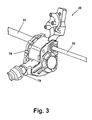
- FIG. 3 is a perspective view of an exemplary power take-off unit constructed in accordance with the teachings of the present invention.
- Figure 4 is a perspective assembly view showing the component parts of the power take-off unit of Figure 3;
- Figure 5 is a perspective view of a rear axle assembly showing a drive unit directly mounted to a rear differential;
- Figure 6 is an exploded perspective view of a drive unit
- Figure 7 is a cross sectional view of a drive unit
- Figure 8 is a schematic view showing another embodiment for a two speed all wheel drive system of the present invention.
- Vehicle 12 may include an engine 14, a transmission 16 and a drive train that may include a center differential 18 and a power take off unit (PTU) 20.
- a PTU input shaft 22 may connect center differential 18 to PTU 20.
- a left half shaft 24 may rotatably couple to center differential 18, providing rotating torque to a left front wheel 26 of a front wheel set 28.
- a right half shaft 30 may rotatably connect through PTU 20 to center differential 18 and provide drive torque to a right front wheel 32.
- Right front wheel 32 and left front wheel 26 both form front wheel set 28.
- Drive torque is distributed from PTU 20 through a prop shaft 34 which may have a first shaft portion 36 and a second shaft portion 38, respectively, to a drive unit 40.
- Drive unit 40 may be directly mounted to a rear axle 42 of vehicle 12 as shown in the particular example provided.
- Rear axle 42 may include a differential 42a, a left rear axle shaft 44, which is coupled to the differential 42a and which transmits rotational torque to a left rear wheel 46 of a rear wheel set 48, and a right rear axle shaft 50, which is also coupled to the differential 42a and which transmits drive torque to a right rear wheel 52. Both right rear wheel 52 and left rear wheel 46 combine to form rear wheel set 48.
- center differential 18 may include a double planetary gear differential assembly 54.
- Differential assembly 54 may include a case right half 56, an input planet carrier 58, an internal gear 60 providing front wheel drive input, a sun gear 62 rotatably disposed within internal gear 60, and a gear shaft 64.
- a planet carrier 66 may provide output torque to right front wheel 32 (shown in Figure 1).
- Gear shaft 64 which forms a portion of right half shaft 30, may be coupled for rotation with planet carrier 66.
- Planet carrier 66 may include a plurality of planet gears 67 each rotatably connected to planet carrier 66 via a pin 68. Planet gears 67 may meshingly engage with a ring gear 69 of internal gear 60.
- Planet carrier 58 may also be provided with a plurality of planet gears (not shown) each connected to planet carrier 58 by a pin (not shown) to operatively create a double planetary gear set rotatably engageable with ring gear 69.
- a sun gear 70 may provide output torque to left front wheel 26 via a gear shaft 71, which forms a portion of left half shaft 24.
- Gear shaft 71 may be rotatably disposed in a case left half 72.
- An input gear 74 may provide input torque to differential assembly 54 directly from transmission 16.
- PTU input shaft 22 may be rotatably driven by rotation of sun gear 62.
- PTU 20 may include a PTU case 76 and a rear output connector 78.
- PTU input shaft 22 is shown at its connection to PTU case 76.
- Rear output connector 78 is fastenably connected to first shaft portion 36 of prop shaft 34, ( Figure 1).
- PTU case 76 may include a center case section 79, a first end plate 80 and a second end plate 82.
- An outer seal 84 may seal PTU input shaft 22 as PTU input shaft 22 penetrates an aperture 86 of second end plate 82.
- PTU input shaft 22 may include a hollow shaft portion 88 which provides internal rotational clearance for right half shaft 30 which may freely rotate and operatively pass through PTU 20 within hollow shaft portion 88.
- Hollow shaft portion 88 may be supported between second end plate 82 and center case section 79 by a first bearing 89 and a second bearing 90.
- Right half shaft 30 may penetrate center case section 79 and be supported between center case section 79 and first end plate 80 by a right half shaft bearing 92.
- Right half shaft 30 may penetrate first end plate 80 via an aperture 94 which may be provided with an outer seal 96.
- PTU input shaft 22 may also include a gear 98.
- gear 98 may meshingly engage an idler gear 100.
- Idler gear 100 may be supported by an outer roller bearing 102 and a bearing race 104 to second end plate 82.
- Idler gear 100 may also be supported by an inner roller bearing 106 and a bearing race 108 to center case section 79.
- An output gear assembly 110 may be provided within center case section 79.
- Output gear assembly 110 may include an output gear 112, a hypoid ring gear 114, and a flange 116 which fastenably supports hypoid ring gear 114 to output gear assembly 110.
- a first end 117 of output gear assembly 110 may be supported by a bearing 118 at second end plate 82.
- a second end 119 of output gear assembly 110 may be supported by a bearing 120 to first end plate 80.
- Hypoid pinion gear 122 may be supported on a rear output gear shaft 124 through a rear aperture 125 of center case section 79.
- Rear output gear shaft 124 may be rotatably supported within center case section 79 by a first bearing 126 and may be supported outside of center case section 79 by a second bearing 128.
- Rear output connector 78 may be splined to rear output gear shaft 124 and fastenably fixed to output gear shaft 124 by a fastener 130.
- At least one seal 132 may also be positioned between rear output connector 78 and center case section 79 at rear aperture 125.
- rotational torque may be applied to PTU input shaft 22 from sun gear 62 of center differential 18 ( Figure 2).
- Gear 98 of PTU input shaft 22 meshingly engages idler gear 100.
- Idler gear 100 in turn meshingly engages output gear 112.
- Rotation of output gear 112 rotates hypoid ring gear 114.
- Drive torque to rear wheel set 48 ( Figure 1) is provided by rotation of hypoid ring gear 114 and hypoid pinion gear 122 which rotates rear output gear shaft 124.
- Rotation of rear output gear shaft 124 rotates rear output connector 78 and thereby rotates prop shaft 34 ( Figure 1).
- Right half shaft 30 rotates within hollow shaft portion 88 of PTU input shaft 22 to provide drive torque directly to right front wheel 32 ( Figure 1).
- a first connector half 134 which is coupled to prop shaft 34, may be coupled to a second connector half 136 that is associated with drive unit 40, to facilitate the transmission of rotary power from the prop shaft 34 to drive unit 40.
- Drive unit 40 may include a housing 138 that may be fastenably connected to the housing of the rear axle 42 (as best seen in reference to Figure 7).
- a shift unit 140 may be coupled to housing 138.
- Drive torque may be transmitted via drive unit 40 through rear axle 42 to rear wheel set 48 (shown in Figure 1).
- Shift unit 140 may include an electrical actuator that may be operated, for example, from an electric power source commonly provided by vehicle 12.
- An exemplary shift unit is manufactured by the Joseph Pollak Corporation of Boston, Massachusetts.
- Shift unit 140 may include a linear actuator (not shown) which translates a shift fork 154 (described in further detail in reference to Figure 6). Shifting of shift unit 140 is not limited to a linear actuator and may also be accomplished using a solenoid operator, a vacuum diaphragm, a hydraulic operator, a cable, etc. as one of ordinary skill in the art will readily appreciate in view of this disclosure.
- drive unit 40 may include a planet carrier 141.
- Planet carrier 141 may include a plurality of pins 142, each supporting one of a plurality of planet gears 143 on a bearing 144.
- Planet carrier 141 may rotate within an internal gear 146.
- a first dog-ring plate 148 may be coupled for rotation with planet carrier 141.
- First dog-ring plate 148 may be connected by a plurality of fasteners (not shown) or otherwise fastenably connected to planet carrier 141.
- a shift collar 150 may meshingly engage internal gear 146 and may translate in either a shift direction "A" or a shift direction "B" within internal gear 146.
- a second dog-ring plate 152 may be fixedly connected to an interior surface of shift collar 150, for example by welding.
- a third dog-ring plate 160 may be fixedly coupled for rotation with second connector half 136.
- a sun gear shaft 161 may be coupled for rotation with second connector half 136 and may be disposed through each of third dog-ring plate 160, shift collar 150, second dog-ring plate 152, first dog-ring plate 148, internal gear 146, and planet carrier 141, where a sun gear 162 of sun gear shaft 161 meshingly engages the plurality of planet gears 143.
- Shift fork 154 may have a pair of tines 156 that may be disposed in an annular channel 158 of shift collar 150 such that displacement of shift fork 154 by shift unit 140 causes shift collar 150 to translate in either of shift direction "A" or shift direction "B".
- Shift fork 154 may be displaced in shift direction "A" to translate shift collar 150 (and second dog-ring plate 152) into a position where a plurality of extensions 166 of second dog-ring plate 152 engage a plurality of mating extensions 164 of first dog-ring plate 148. Displacement in shift direction "A” locks internal gear 146 to planet carrier 141 to facilitate torque transmission between second connector half 136 and planet carrier 141 in a high range or relatively high speed ratio. This results in rotation of each of planet carrier 141, internal gear 146 and sun gear shaft 161.
- Shift fork 154 may also be displaced in shift direction "B" to translate shift collar 150 (and second dog-ring plate 152) into a position where a plurality of extensions 168 on an opposite side of second dog-ring plate 152 engage a plurality of extensions 170 on third dog-ring plate 160.
- internal gear 146 is locked in a stationary, non-rotating condition that permits planet gears 143 to perform a speed reduction and torque multiplication operation so that torque is transmitted between second connector half 136 and planet carrier 141 in a low range, or relatively low speed ratio.
- rear axle 42 may include an input pinion 172, which may have a splined input shaft 174, that transmits rotary power to the differential 42a in a manner that is well known in the art.
- the input pinion 172 may transmit rotary power to a ring gear (not shown) of the differential 42a, which causes the differential 42a to rotate within the housing of the rear axle 42.
- a gear set (not shown), which may include a pair of side gears (not shown) and a plurality of pinions (not shown), may be employed to transmit rotary power to the left and right axle shafts 44 and 50 (Fig. 1).
- a fastener 176 such as a nut or a bolt, may be employed to fixedly, but removably couple planet carrier 141 to input shaft 174.
- Input shaft 174 may meshingly engage a mating internally splined portion 177 of planet carrier 141.
- Housing 138 may include a housing flange 178.
- An axle may be rotatably housed within a differential housing 179 that may include a differential flange 180. Housing flange 178 and differential flange 180 are fixedly, but removably coupled together using a plurality of fasteners 181.
- Housing 138 may also include a pilot feature 182 that slidably engages a mating feature 183 of differential flange 180, so as to permit various components of drive unit 40 and rear axle 42 (such as including input pinion 172) to be aligned about a common centerline "C".
- Sun gear shaft 161 may be rotatably supported within housing 138 along common centerline "C" by a bearing set 184.
- a shaft seal 186 may be employed to seal an end junction of housing 138.
- Sun gear 162 of sun gear shaft 161 meshingly engages the plurality of planet gears 143.
- Planet gears 143 in turn rotatably engage an internally toothed surface of internal gear 146.
- Internal gear 146 is rotatably supported on an outer diameter of planet carrier 141 by a first bearing 188 and a second bearing 190.
- a plurality of fasteners 192 may be employed to fixedly, but removably couple third dog-ring plate 160 to a portion of housing 138.
- Figure 7 shows a configuration for drive unit 40 during the high range or high speed mode condition of operation in a portion of drive unit 40 below common centerline "C".
- the low range or low speed mode of operation configuration is shown above common centerline "C”.
- shift collar 150 is shifted such that second dog-ring plate 152 and first dog-ring plate 148 engage together.
- second dog-ring extensions 166 engage with respective ones of first dog-ring extensions 164 such that input torque received via sun gear shaft 161 is transferred via planet gears 143 to internal gear 146, and from shift collar 150 to planet carrier 141.
- Planet carrier 141 thereby transmits high range torque via input pinion 172 to the ring gear (not shown) of differential 42a.
- shift collar 150 is displaced to the right as viewed in Figure 7 which causes extensions 168 of second dog-ring plate 152 to engage respective ones of third dog-ring extensions 170 of third dog-ring plate 160. Because third dog-ring plate 160 is fixedly engaged to housing 138, internal gear 146 is thereby grounded via shift collar 150 to housing 138 and internal gear 146 cannot rotate. Rotational torque from sun gear shaft 161 is therefore transferred in low range via sun gear 162 to planet gears 143 and directly to planet carrier 141 such that planet carrier 141 is driven at a predetermined speed ratio relative to sun gear 162, such as at a 1:3 ratio.
- output torque from engine 14 is transferred via transmission 16 to center differential 18, from center differential 18 to PTU 20 and therefrom to drive unit 40.
- Center differential 18 and PTU 20 operate in both high range and low range modes.
- All wheel drive system 10 in high range or high speed operating mode may split drive torque in a first front/rear percentage, such as approximately 67% to the front wheel set 28 (approximately evenly divided between each of left front wheel 26 and front right wheel 32) and approximately 33% to PTU 20.
- torque from PTU 20 is transferred via prop shaft 34 to drive unit 40.
- PTU 20 may have a gear ratio of 1:2.73.
- shift unit 140 In the high range or high speed operating mode, shift unit 140 translates shift fork 154 in shift direction "A" ( Figure 6), drive torque is multiplied by a first ratio and is output via planet carrier 141 and input pinion 172 to the ring gear (not shown) of differential 42a where the transmission 16 torque may be approximately evenly divided between left rear wheel 46 and right rear wheel 52.
- two speed all wheel drive system 10 may split drive torque in a second front/rear percentage, such as approximately 38% to the front wheel set 28 (approximately evenly divided between each of left front wheel 26 and front right wheel 32) and approximately 62% to PTU 20.
- shift unit 140 translates shift fork 154 in shift direction "B" ( Figure 6).
- Drive torque is multiplied by a second ratio and is output via planet carrier 141 and input pinion 172 to the ring gear (not shown) of rear differential 42a where the torque from PTU 20 may be approximately evenly divided between left rear wheel 46 and right rear wheel 52.
- center differential 18 is effectively operated as a reduction gear set.
- front wheel set 28 receives approximately 67% of the transmission 16 torque
- rear wheel set 48 receives approximately 108% of transmission 16 torque.
- a drive unit 194 similar to drive unit 40, may be directly mounted to PTU 20.
- a shift unit 196 similar to shift unit 140, is mounted on drive unit 194 and operates similar to shift unit 140.
- a housing flange 198 (shown diagrammatically in this view only) is used to directly mate drive unit 194 to a mounting flange (not shown) of PTU 20.
- Drive unit 194 operates similar to drive unit 40 to provide either a high range/high speed operating mode or a low range /low speed operating mode.
- Power take-off unit 20 may be operated as a single speed or a two speed unit.
- PTU 20 may provide a two speed operation having a gear ratio of 1:0.61 in the low range all-wheel drive operation and a gear ratio of 1:2.73 in the high range all-wheel drive operation.
- Two speed all wheel drive system 10 of the present invention is effective to provide both a high range/high speed and a low range/low speed operating mode for all wheel drive vehicles regardless of wheel slip conditions. This permits both on-road (high range operation) and off-road (low range operation) drivability without significant power loss and with no vehicle speed limitation in at least high range.
- Low range operation may be engaged with the vehicle stopped or at very low operating speed to protect drive train components.
- a vehicle speed lock-out system (not shown), known in the art, may also be used to prevent engagement of an all wheel drive system of the present invention from high range/high speed operation to low range/low speed operation at either a predetermined vehicle speed or to preclude operation at a vehicle speed greater than zero.
- Left rear axle shaft 44 and right rear axle shaft 50 in the example shown in Figure 1 form a solid rear axle assembly.
- the invention is not limited to the configuration shown in Figure 1.
- the invention may also be applicable to independent suspension systems (not shown).
Landscapes
- Engineering & Computer Science (AREA)
- Chemical & Material Sciences (AREA)
- Combustion & Propulsion (AREA)
- Transportation (AREA)
- Mechanical Engineering (AREA)
- Food Science & Technology (AREA)
- Arrangement And Driving Of Transmission Devices (AREA)
- Retarders (AREA)
Applications Claiming Priority (2)
| Application Number | Priority Date | Filing Date | Title |
|---|---|---|---|
| US797717 | 2004-03-10 | ||
| US10/797,717 US7207409B2 (en) | 2004-03-10 | 2004-03-10 | Two speed all wheel drive system |
Publications (3)
| Publication Number | Publication Date |
|---|---|
| EP1574383A2 true EP1574383A2 (de) | 2005-09-14 |
| EP1574383A3 EP1574383A3 (de) | 2006-01-18 |
| EP1574383B1 EP1574383B1 (de) | 2011-05-25 |
Family
ID=34827640
Family Applications (1)
| Application Number | Title | Priority Date | Filing Date |
|---|---|---|---|
| EP05004443A Active EP1574383B1 (de) | 2004-03-10 | 2005-03-01 | Zweigang Allradantriebssystem |
Country Status (5)
| Country | Link |
|---|---|
| US (2) | US7207409B2 (de) |
| EP (1) | EP1574383B1 (de) |
| JP (1) | JP4870934B2 (de) |
| KR (1) | KR100785692B1 (de) |
| BR (1) | BRPI0500776B1 (de) |
Families Citing this family (19)
| Publication number | Priority date | Publication date | Assignee | Title |
|---|---|---|---|---|
| CA2657110A1 (en) | 2006-08-02 | 2008-02-07 | Magna Powertrain Usa, Inc. | Two-speed power take-off unit |
| US8449467B2 (en) * | 2006-11-28 | 2013-05-28 | Siemens Medical Solutions Usa, Inc. | Helical acoustic array for medical ultrasound |
| JP2008184086A (ja) * | 2007-01-31 | 2008-08-14 | Fuji Heavy Ind Ltd | 4輪駆動車の動力伝達装置 |
| EP2150431B1 (de) | 2007-04-30 | 2011-08-17 | Parker Hannifin Corporation | Hydraulisch betriebener schalter zur leistungsaufnahme |
| US8172712B2 (en) * | 2007-05-29 | 2012-05-08 | Chrysler Group Llc | Compact power transfer unit for transaxle applications |
| US8287421B2 (en) * | 2008-07-10 | 2012-10-16 | General Electric Company | Transmission and power generation system having torque reacting joint |
| DE112010004718T5 (de) | 2009-12-08 | 2012-09-20 | American Axle & Manufacturing, Inc. | Entkoppelbare Heckantriebsachse für in Längsrichtung angeordnete Antriebsstränge |
| US9731598B2 (en) | 2010-07-23 | 2017-08-15 | Fca Us Llc | Multi-mode drive system for transaxle applications |
| KR101904444B1 (ko) | 2011-04-18 | 2018-10-04 | 지케이엔 드라이브라인 뉴톤, 엘엘씨 | 동력 전달 유닛 |
| EP2699441B1 (de) | 2011-04-20 | 2017-06-07 | GKN Driveline Newton, LLC | Leistungsübertragungseinheit |
| US8961353B2 (en) | 2012-05-14 | 2015-02-24 | American Axle & Manufacturing, Inc. | Two-speed disconnecting driveline with one reduction gearset |
| US8784254B2 (en) | 2012-05-14 | 2014-07-22 | American Axle & Manufacturing, Inc. | Power transmitting component |
| US8795126B2 (en) | 2012-05-14 | 2014-08-05 | American Axle & Manufacturing, Inc. | Disconnectable driveline for all-wheel drive vehicle |
| WO2013188647A1 (en) * | 2012-06-15 | 2013-12-19 | American Axle & Manufacturing, Inc. | Disconnectable driveline with a multi-speed rdm and ptu |
| DE112013004889B4 (de) | 2012-10-05 | 2022-02-17 | American Axle & Manufacturing, Inc. | Trennende Ein-Gang und Zwei-Gang-Achsanordnungen |
| US9062744B2 (en) | 2013-03-13 | 2015-06-23 | American Axle & Manufacturing, Inc. | Two-speed drive module |
| CN105564232B (zh) | 2014-10-17 | 2019-02-22 | 美国轮轴制造公司 | 具有与管状驱动构件整体形成的环形齿轮的动力传动部件 |
| JP2018144099A (ja) * | 2017-03-09 | 2018-09-20 | 武蔵精密工業株式会社 | ドグクラッチ用ドグの鍛造方法及びドグクラッチ用ドグ |
| CN114008343B (zh) * | 2019-06-28 | 2024-03-15 | Gkn汽车有限公司 | 用于车辆动力传递单元的多级换挡致动器 |
Citations (1)
| Publication number | Priority date | Publication date | Assignee | Title |
|---|---|---|---|---|
| EP0590265A1 (de) | 1992-09-26 | 1994-04-06 | Dr.Ing.h.c. F. Porsche Aktiengesellschaft | Antrieb eines Geländewagens |
Family Cites Families (25)
| Publication number | Priority date | Publication date | Assignee | Title |
|---|---|---|---|---|
| US2312263A (en) * | 1940-12-23 | 1943-02-23 | Clark Equipment Co | Two-speed axle |
| US3370486A (en) * | 1963-11-22 | 1968-02-27 | Axel Wickman Transmissions Ltd | Vehicular driving axle |
| JPS59176121A (ja) | 1983-03-24 | 1984-10-05 | Kubota Ltd | 四輪駆動車輛の前輪駆動制御装置 |
| JPS61223366A (ja) * | 1985-03-28 | 1986-10-03 | Nissan Motor Co Ltd | 4輪駆動車の動力伝達装置 |
| JPS62203826A (ja) * | 1986-02-28 | 1987-09-08 | Fuji Heavy Ind Ltd | 4輪駆動車のトルク配分制御装置 |
| JPH0765660B2 (ja) | 1986-04-10 | 1995-07-19 | トヨタ自動車株式会社 | 車両用動力分配装置 |
| AT390410B (de) * | 1986-04-29 | 1990-05-10 | Steyr Daimler Puch Ag | Antriebsanordnung fuer kraftfahrzeuge mit wenigstens zwei triebachsen |
| DE3621225C1 (de) | 1986-06-25 | 1987-05-27 | Daimler Benz Ag | Steuereinrichtung fuer die zeitweise Umschaltung eines Fahrzeugantriebes von einachsigem Antrieb ueber eine permanent angetriebene Fahrzeugachse auf zweiachsigen Antrieb |
| JPS6390436A (ja) * | 1986-10-01 | 1988-04-21 | Kubota Ltd | 四輪駆動型作業車の走行用伝動構造 |
| AT396093B (de) * | 1987-11-23 | 1993-05-25 | Steyr Daimler Puch Ag | Antriebsanordnung fuer ein kraftfahrzeug |
| JPH0761779B2 (ja) * | 1988-03-14 | 1995-07-05 | 本田技研工業株式会社 | 車両の前後輪駆動装置 |
| GB2239922B (en) * | 1989-11-14 | 1993-07-14 | Honda Motor Co Ltd | Power transmission apparatus for a four-wheel drive vehicle |
| US5045036A (en) | 1990-12-11 | 1991-09-03 | Dana Corporation | Electromagnetic speed change apparatus |
| AT407027B (de) | 1994-04-19 | 2000-11-27 | Steyr Daimler Puch Ag | Antriebsanordnung für ein allradgetriebenes kraftfahrzeug |
| JP3554841B2 (ja) | 1997-02-07 | 2004-08-18 | 光洋精工株式会社 | 自動車の舵取装置 |
| JP2002087095A (ja) | 2000-09-12 | 2002-03-26 | Komatsu Ltd | 車両のタイヤロック防止装置 |
| US6513615B2 (en) | 2001-03-26 | 2003-02-04 | New Venture Gear, Inc. | Full-time all-wheel drive power take-off unit for motor vehicle |
| US6942055B2 (en) * | 2001-04-05 | 2005-09-13 | Magna Drivetrain Of America, Inc. | Electronically-controlled rear module for all-wheel drive system |
| US6568519B2 (en) * | 2001-08-10 | 2003-05-27 | Borgwarner, Inc. | Torque limiting chain sprocket assembly |
| US6605018B2 (en) | 2001-08-23 | 2003-08-12 | Visteon Global Technologies, Inc. | Power transfer unit |
| US6725744B2 (en) * | 2001-08-27 | 2004-04-27 | Visteon Global Technologies, Inc. | Power train assembly |
| US6620071B1 (en) | 2002-03-27 | 2003-09-16 | Visteon Global Technologies, Inc. | Power takeoff unit with center differential construction |
| EP1355209A1 (de) | 2002-04-18 | 2003-10-22 | Ford Global Technologies, LLC | Fahrzeugsteuerungssystem |
| US20050087380A1 (en) * | 2003-10-24 | 2005-04-28 | Todd Brown | Variator in a four wheel drive |
| US6942592B1 (en) * | 2004-02-24 | 2005-09-13 | General Motors Corporation | All wheel drive/four wheel drive transfer case with different front and rear axle ratios |
-
2004
- 2004-03-10 US US10/797,717 patent/US7207409B2/en active Active
-
2005
- 2005-03-01 EP EP05004443A patent/EP1574383B1/de active Active
- 2005-03-08 BR BRPI0500776-3A patent/BRPI0500776B1/pt active IP Right Grant
- 2005-03-09 JP JP2005065934A patent/JP4870934B2/ja active Active
- 2005-03-10 KR KR1020050020292A patent/KR100785692B1/ko active IP Right Grant
-
2006
- 2006-11-21 US US11/602,766 patent/US7416505B2/en active Active
Patent Citations (1)
| Publication number | Priority date | Publication date | Assignee | Title |
|---|---|---|---|---|
| EP0590265A1 (de) | 1992-09-26 | 1994-04-06 | Dr.Ing.h.c. F. Porsche Aktiengesellschaft | Antrieb eines Geländewagens |
Also Published As
| Publication number | Publication date |
|---|---|
| JP2005255157A (ja) | 2005-09-22 |
| US7207409B2 (en) | 2007-04-24 |
| US20050199437A1 (en) | 2005-09-15 |
| US20070084660A1 (en) | 2007-04-19 |
| US7416505B2 (en) | 2008-08-26 |
| BRPI0500776B1 (pt) | 2018-07-24 |
| KR20060043850A (ko) | 2006-05-15 |
| EP1574383B1 (de) | 2011-05-25 |
| BRPI0500776A (pt) | 2005-11-01 |
| EP1574383A3 (de) | 2006-01-18 |
| KR100785692B1 (ko) | 2007-12-14 |
| JP4870934B2 (ja) | 2012-02-08 |
Similar Documents
| Publication | Publication Date | Title |
|---|---|---|
| EP1574383B1 (de) | Zweigang Allradantriebssystem | |
| US8814740B2 (en) | Two-speed power take-off unit with mode clutch | |
| US4431079A (en) | Four-wheel vehicle drive system | |
| US7703353B2 (en) | Drive unit connected to a transmission output for producing forward and reverse device | |
| US9162567B2 (en) | Single speed and two-speed disconnecting axle arrangements | |
| US4441575A (en) | Four-wheel vehicle drive system | |
| US5083478A (en) | Four-wheel vehicle drive system | |
| US6152848A (en) | Shift-on-move range system for full-time transfer case | |
| EP1072457A1 (de) | Getriebeeinheit bestehend aus schrägverzahnten Umlaufgetriebesätzen | |
| GB2454563A (en) | A power take-off for all-wheel-drive systems | |
| EP3885177B1 (de) | Antriebsachsensystem | |
| US9108511B2 (en) | Transfer case | |
| EP0876933A2 (de) | Adapter für Verteilergetriebe | |
| US7062984B2 (en) | Vehicle powertrain with two-wheel and four-wheel drive ratios | |
| US11161408B2 (en) | Three speed transfer case for four wheel drive vehicles | |
| US8449430B2 (en) | Transversely mounted transaxle having a low range gear assembly and powertrain for a vehicle including same | |
| US10670128B2 (en) | All-wheel drive driveline with front limited slip differential |
Legal Events
| Date | Code | Title | Description |
|---|---|---|---|
| PUAI | Public reference made under article 153(3) epc to a published international application that has entered the european phase |
Free format text: ORIGINAL CODE: 0009012 |
|
| AK | Designated contracting states |
Kind code of ref document: A2 Designated state(s): AT BE BG CH CY CZ DE DK EE ES FI FR GB GR HU IE IS IT LI LT LU MC NL PL PT RO SE SI SK TR |
|
| AX | Request for extension of the european patent |
Extension state: AL BA HR LV MK YU |
|
| PUAL | Search report despatched |
Free format text: ORIGINAL CODE: 0009013 |
|
| RIC1 | Information provided on ipc code assigned before grant |
Ipc: B60K 17/346 19850101ALI20051116BHEP Ipc: B60K 17/28 19680901AFI20050616BHEP |
|
| AK | Designated contracting states |
Kind code of ref document: A3 Designated state(s): AT BE BG CH CY CZ DE DK EE ES FI FR GB GR HU IE IS IT LI LT LU MC NL PL PT RO SE SI SK TR |
|
| AX | Request for extension of the european patent |
Extension state: AL BA HR LV MK YU |
|
| 17P | Request for examination filed |
Effective date: 20060519 |
|
| AKX | Designation fees paid |
Designated state(s): DE ES FR GB IT |
|
| 17Q | First examination report despatched |
Effective date: 20060901 |
|
| GRAP | Despatch of communication of intention to grant a patent |
Free format text: ORIGINAL CODE: EPIDOSNIGR1 |
|
| GRAS | Grant fee paid |
Free format text: ORIGINAL CODE: EPIDOSNIGR3 |
|
| GRAA | (expected) grant |
Free format text: ORIGINAL CODE: 0009210 |
|
| AK | Designated contracting states |
Kind code of ref document: B1 Designated state(s): DE ES FR GB IT |
|
| REG | Reference to a national code |
Ref country code: GB Ref legal event code: FG4D |
|
| REG | Reference to a national code |
Ref country code: DE Ref legal event code: R096 Ref document number: 602005028196 Country of ref document: DE Effective date: 20110707 |
|
| PG25 | Lapsed in a contracting state [announced via postgrant information from national office to epo] |
Ref country code: ES Free format text: LAPSE BECAUSE OF FAILURE TO SUBMIT A TRANSLATION OF THE DESCRIPTION OR TO PAY THE FEE WITHIN THE PRESCRIBED TIME-LIMIT Effective date: 20110905 |
|
| PLBE | No opposition filed within time limit |
Free format text: ORIGINAL CODE: 0009261 |
|
| STAA | Information on the status of an ep patent application or granted ep patent |
Free format text: STATUS: NO OPPOSITION FILED WITHIN TIME LIMIT |
|
| 26N | No opposition filed |
Effective date: 20120228 |
|
| PG25 | Lapsed in a contracting state [announced via postgrant information from national office to epo] |
Ref country code: IT Free format text: LAPSE BECAUSE OF FAILURE TO SUBMIT A TRANSLATION OF THE DESCRIPTION OR TO PAY THE FEE WITHIN THE PRESCRIBED TIME-LIMIT Effective date: 20110525 |
|
| REG | Reference to a national code |
Ref country code: DE Ref legal event code: R097 Ref document number: 602005028196 Country of ref document: DE Effective date: 20120228 |
|
| GBPC | Gb: european patent ceased through non-payment of renewal fee |
Effective date: 20120301 |
|
| REG | Reference to a national code |
Ref country code: FR Ref legal event code: ST Effective date: 20121130 |
|
| PG25 | Lapsed in a contracting state [announced via postgrant information from national office to epo] |
Ref country code: FR Free format text: LAPSE BECAUSE OF NON-PAYMENT OF DUE FEES Effective date: 20120402 Ref country code: GB Free format text: LAPSE BECAUSE OF NON-PAYMENT OF DUE FEES Effective date: 20120301 |
|
| PGFP | Annual fee paid to national office [announced via postgrant information from national office to epo] |
Ref country code: DE Payment date: 20230321 Year of fee payment: 19 |