EP3885177B1 - Antriebsachsensystem - Google Patents
Antriebsachsensystem Download PDFInfo
- Publication number
- EP3885177B1 EP3885177B1 EP21152727.0A EP21152727A EP3885177B1 EP 3885177 B1 EP3885177 B1 EP 3885177B1 EP 21152727 A EP21152727 A EP 21152727A EP 3885177 B1 EP3885177 B1 EP 3885177B1
- Authority
- EP
- European Patent Office
- Prior art keywords
- gear
- axle assembly
- interaxle differential
- assembly
- differential unit
- Prior art date
- Legal status (The legal status is an assumption and is not a legal conclusion. Google has not performed a legal analysis and makes no representation as to the accuracy of the status listed.)
- Active
Links
- 125000006850 spacer group Chemical group 0.000 claims description 3
- 241000239290 Araneae Species 0.000 description 44
- 230000000712 assembly Effects 0.000 description 23
- 238000000429 assembly Methods 0.000 description 23
- 239000003381 stabilizer Substances 0.000 description 8
- 230000008878 coupling Effects 0.000 description 4
- 238000010168 coupling process Methods 0.000 description 4
- 238000005859 coupling reaction Methods 0.000 description 4
- 230000001133 acceleration Effects 0.000 description 2
- 230000005540 biological transmission Effects 0.000 description 2
- 239000000314 lubricant Substances 0.000 description 2
- 238000005096 rolling process Methods 0.000 description 2
- 230000009194 climbing Effects 0.000 description 1
- 239000000446 fuel Substances 0.000 description 1
- 230000002401 inhibitory effect Effects 0.000 description 1
- 230000013011 mating Effects 0.000 description 1
- 230000036316 preload Effects 0.000 description 1
- 238000011144 upstream manufacturing Methods 0.000 description 1
Images


Classifications
-
- B—PERFORMING OPERATIONS; TRANSPORTING
- B60—VEHICLES IN GENERAL
- B60K—ARRANGEMENT OR MOUNTING OF PROPULSION UNITS OR OF TRANSMISSIONS IN VEHICLES; ARRANGEMENT OR MOUNTING OF PLURAL DIVERSE PRIME-MOVERS IN VEHICLES; AUXILIARY DRIVES FOR VEHICLES; INSTRUMENTATION OR DASHBOARDS FOR VEHICLES; ARRANGEMENTS IN CONNECTION WITH COOLING, AIR INTAKE, GAS EXHAUST OR FUEL SUPPLY OF PROPULSION UNITS IN VEHICLES
- B60K17/00—Arrangement or mounting of transmissions in vehicles
- B60K17/04—Arrangement or mounting of transmissions in vehicles characterised by arrangement, location, or kind of gearing
- B60K17/16—Arrangement or mounting of transmissions in vehicles characterised by arrangement, location, or kind of gearing of differential gearing
- B60K17/165—Arrangement or mounting of transmissions in vehicles characterised by arrangement, location, or kind of gearing of differential gearing provided between independent half axles
-
- B—PERFORMING OPERATIONS; TRANSPORTING
- B60—VEHICLES IN GENERAL
- B60K—ARRANGEMENT OR MOUNTING OF PROPULSION UNITS OR OF TRANSMISSIONS IN VEHICLES; ARRANGEMENT OR MOUNTING OF PLURAL DIVERSE PRIME-MOVERS IN VEHICLES; AUXILIARY DRIVES FOR VEHICLES; INSTRUMENTATION OR DASHBOARDS FOR VEHICLES; ARRANGEMENTS IN CONNECTION WITH COOLING, AIR INTAKE, GAS EXHAUST OR FUEL SUPPLY OF PROPULSION UNITS IN VEHICLES
- B60K17/00—Arrangement or mounting of transmissions in vehicles
- B60K17/26—Arrangement or mounting of transmissions in vehicles characterised by arrangement, location, of type of freewheel device
-
- B—PERFORMING OPERATIONS; TRANSPORTING
- B60—VEHICLES IN GENERAL
- B60K—ARRANGEMENT OR MOUNTING OF PROPULSION UNITS OR OF TRANSMISSIONS IN VEHICLES; ARRANGEMENT OR MOUNTING OF PLURAL DIVERSE PRIME-MOVERS IN VEHICLES; AUXILIARY DRIVES FOR VEHICLES; INSTRUMENTATION OR DASHBOARDS FOR VEHICLES; ARRANGEMENTS IN CONNECTION WITH COOLING, AIR INTAKE, GAS EXHAUST OR FUEL SUPPLY OF PROPULSION UNITS IN VEHICLES
- B60K17/00—Arrangement or mounting of transmissions in vehicles
- B60K17/02—Arrangement or mounting of transmissions in vehicles characterised by arrangement, location, or kind of clutch
-
- B—PERFORMING OPERATIONS; TRANSPORTING
- B60—VEHICLES IN GENERAL
- B60K—ARRANGEMENT OR MOUNTING OF PROPULSION UNITS OR OF TRANSMISSIONS IN VEHICLES; ARRANGEMENT OR MOUNTING OF PLURAL DIVERSE PRIME-MOVERS IN VEHICLES; AUXILIARY DRIVES FOR VEHICLES; INSTRUMENTATION OR DASHBOARDS FOR VEHICLES; ARRANGEMENTS IN CONNECTION WITH COOLING, AIR INTAKE, GAS EXHAUST OR FUEL SUPPLY OF PROPULSION UNITS IN VEHICLES
- B60K17/00—Arrangement or mounting of transmissions in vehicles
- B60K17/22—Arrangement or mounting of transmissions in vehicles characterised by arrangement, location, or type of main drive shafting, e.g. cardan shaft
- B60K17/24—Arrangements of mountings for shafting
-
- B—PERFORMING OPERATIONS; TRANSPORTING
- B60—VEHICLES IN GENERAL
- B60K—ARRANGEMENT OR MOUNTING OF PROPULSION UNITS OR OF TRANSMISSIONS IN VEHICLES; ARRANGEMENT OR MOUNTING OF PLURAL DIVERSE PRIME-MOVERS IN VEHICLES; AUXILIARY DRIVES FOR VEHICLES; INSTRUMENTATION OR DASHBOARDS FOR VEHICLES; ARRANGEMENTS IN CONNECTION WITH COOLING, AIR INTAKE, GAS EXHAUST OR FUEL SUPPLY OF PROPULSION UNITS IN VEHICLES
- B60K17/00—Arrangement or mounting of transmissions in vehicles
- B60K17/34—Arrangement or mounting of transmissions in vehicles for driving both front and rear wheels, e.g. four wheel drive vehicles
- B60K17/344—Arrangement or mounting of transmissions in vehicles for driving both front and rear wheels, e.g. four wheel drive vehicles having a transfer gear
- B60K17/346—Arrangement or mounting of transmissions in vehicles for driving both front and rear wheels, e.g. four wheel drive vehicles having a transfer gear the transfer gear being a differential gear
- B60K17/3462—Arrangement or mounting of transmissions in vehicles for driving both front and rear wheels, e.g. four wheel drive vehicles having a transfer gear the transfer gear being a differential gear with means for changing distribution of torque between front and rear wheels
- B60K17/3465—Arrangement or mounting of transmissions in vehicles for driving both front and rear wheels, e.g. four wheel drive vehicles having a transfer gear the transfer gear being a differential gear with means for changing distribution of torque between front and rear wheels self-actuated means, e.g. differential locked automatically by difference of speed
-
- B—PERFORMING OPERATIONS; TRANSPORTING
- B60—VEHICLES IN GENERAL
- B60K—ARRANGEMENT OR MOUNTING OF PROPULSION UNITS OR OF TRANSMISSIONS IN VEHICLES; ARRANGEMENT OR MOUNTING OF PLURAL DIVERSE PRIME-MOVERS IN VEHICLES; AUXILIARY DRIVES FOR VEHICLES; INSTRUMENTATION OR DASHBOARDS FOR VEHICLES; ARRANGEMENTS IN CONNECTION WITH COOLING, AIR INTAKE, GAS EXHAUST OR FUEL SUPPLY OF PROPULSION UNITS IN VEHICLES
- B60K17/00—Arrangement or mounting of transmissions in vehicles
- B60K17/36—Arrangement or mounting of transmissions in vehicles for driving tandem wheels
-
- F—MECHANICAL ENGINEERING; LIGHTING; HEATING; WEAPONS; BLASTING
- F16—ENGINEERING ELEMENTS AND UNITS; GENERAL MEASURES FOR PRODUCING AND MAINTAINING EFFECTIVE FUNCTIONING OF MACHINES OR INSTALLATIONS; THERMAL INSULATION IN GENERAL
- F16H—GEARING
- F16H37/00—Combinations of mechanical gearings, not provided for in groups F16H1/00 - F16H35/00
- F16H37/02—Combinations of mechanical gearings, not provided for in groups F16H1/00 - F16H35/00 comprising essentially only toothed or friction gearings
- F16H37/06—Combinations of mechanical gearings, not provided for in groups F16H1/00 - F16H35/00 comprising essentially only toothed or friction gearings with a plurality of driving or driven shafts; with arrangements for dividing torque between two or more intermediate shafts
- F16H37/08—Combinations of mechanical gearings, not provided for in groups F16H1/00 - F16H35/00 comprising essentially only toothed or friction gearings with a plurality of driving or driven shafts; with arrangements for dividing torque between two or more intermediate shafts with differential gearing
- F16H37/0806—Combinations of mechanical gearings, not provided for in groups F16H1/00 - F16H35/00 comprising essentially only toothed or friction gearings with a plurality of driving or driven shafts; with arrangements for dividing torque between two or more intermediate shafts with differential gearing with a plurality of driving or driven shafts
- F16H37/0813—Combinations of mechanical gearings, not provided for in groups F16H1/00 - F16H35/00 comprising essentially only toothed or friction gearings with a plurality of driving or driven shafts; with arrangements for dividing torque between two or more intermediate shafts with differential gearing with a plurality of driving or driven shafts with only one input shaft
- F16H37/082—Combinations of mechanical gearings, not provided for in groups F16H1/00 - F16H35/00 comprising essentially only toothed or friction gearings with a plurality of driving or driven shafts; with arrangements for dividing torque between two or more intermediate shafts with differential gearing with a plurality of driving or driven shafts with only one input shaft and additional planetary reduction gears
-
- F—MECHANICAL ENGINEERING; LIGHTING; HEATING; WEAPONS; BLASTING
- F16—ENGINEERING ELEMENTS AND UNITS; GENERAL MEASURES FOR PRODUCING AND MAINTAINING EFFECTIVE FUNCTIONING OF MACHINES OR INSTALLATIONS; THERMAL INSULATION IN GENERAL
- F16H—GEARING
- F16H48/00—Differential gearings
- F16H48/05—Multiple interconnected differential sets
-
- F—MECHANICAL ENGINEERING; LIGHTING; HEATING; WEAPONS; BLASTING
- F16—ENGINEERING ELEMENTS AND UNITS; GENERAL MEASURES FOR PRODUCING AND MAINTAINING EFFECTIVE FUNCTIONING OF MACHINES OR INSTALLATIONS; THERMAL INSULATION IN GENERAL
- F16H—GEARING
- F16H48/00—Differential gearings
- F16H48/06—Differential gearings with gears having orbital motion
- F16H48/08—Differential gearings with gears having orbital motion comprising bevel gears
Definitions
- This disclosure relates to a drive axle system that may have a one-way freewheel clutch that enables and disables the transmission of torque to an axle assembly.
- a drive axle system having an inter-axle differential that is a planetary differential is disclosed in U.S. Patent No. 8,523,738 .
- GB1210964A discloses a differential drive arrangement that has a one-way clutch that locks up when the front wheels slip and the speed of a first rotary member reaches the speed of a second rotary member.
- US2019/0248234A1 discloses an axle assembly that has a planetary interaxle differential unit or a bevel gear interaxle differential unit.
- US2019/0111781A1 discloses multiple versions of axle assemblies that have a gear reduction unit disposed upstream from an interaxle differential unit.
- DE19807578A1 discloses a bi-directional one-way clutch that is coupled to front and rear axle drive shafts.
- a drive axle system is provided, as set out in claim 1.
- the interaxle differential unit may transmit torque to the first axle assembly but not to the second axle assembly when the interaxle differential unit is unlocked and the first gear ratio is less than the second gear ratio.
- the interaxle differential unit may transmit torque to the second axle assembly but not to the first axle assembly when the interaxle differential unit is unlocked and the second gear ratio is less than the first gear ratio.
- the first differential assembly may be rotatable about a first differential axis.
- the second differential assembly is rotatable about a second differential axis.
- the one-way freewheel clutch may transmit torque between the first axle assembly and the second axle assembly such that the first differential assembly may be rotatable in a first rotational direction about the first differential axis and the second differential assembly is rotatable in the first rotational direction about the second differential axis when the interaxle differential unit is unlocked.
- the one-way freewheel clutch may transmit torque to the first axle assembly to rotate the first differential assembly about the first differential axis in a second rotational direction, such as a reverse direction that is opposite the first rotational direction, when the first gear ratio is less than the second gear ratio and the interaxle differential unit is locked.
- the one-way freewheel clutch may transmit torque to the second axle assembly to rotate the second differential assembly about the second differential axis in a second rotational direction, such as a reverse direction that is opposite the first rotational direction, when the second gear ratio is less than the first gear ratio and the interaxle differential unit is locked.
- the interaxle differential unit may be disposed in the first axle assembly.
- the interaxle differential unit and the first drive pinion may be rotatable about a first axis.
- the one-way freewheel clutch may be provided with the interaxle differential unit.
- the interaxle differential unit may include a first side gear that may receive the first drive pinion, a second side gear that may be fixed to an output shaft, and a pinion gear that meshes with the first side gear and the second side gear.
- the one-way freewheel clutch may receive the first drive pinion and may be received in the first side gear.
- the one-way freewheel clutch may couple the first side gear to the first drive pinion such that the first side gear and the pinion gear are rotatable together when torque is provided to the first side gear in a first direction.
- the one-way freewheel clutch may permit rotation of the first side gear with respect to the first drive pinion when torque is provided in a second direction that is opposite the first direction.
- the interaxle differential unit may include a case that receives the first side gear, the second side gear, and the pinion gear.
- An interaxle differential lock may selectively couple the first side gear to the case such that the first side gear and the case are rotatable together when the interaxle differential lock is in a locked position and the case is rotatable with respect to the first side gear when the interaxle differential lock is in an unlocked position.
- the one-way freewheel clutch may be received in the case.
- the interaxle differential lock may include a disc pack that may extend around the first side gear and may be received in the case.
- the interaxle differential unit may include a planet carrier that may be rotatable about an axis with an input shaft, a planetary ring gear that may be rotatable about the axis with an output shaft, a sun gear that may receive the first drive pinion, and a planet gear that may be rotatably disposed on the planet carrier and may mesh with the planetary ring gear and the sun gear.
- the one-way freewheel clutch may be received in the sun gear.
- the one-way freewheel clutch may receive the first drive pinion.
- the one-way freewheel clutch may couple the sun gear to the first drive pinion such that the sun gear and the first drive pinion may be rotatable together when the torque is provided to the sun gear in a first direction.
- the one-way freewheel clutch may permit rotation of the sun gear with respect to the first drive pinion when torque is provided in a second direction that is opposite the first direction.
- the interaxle differential unit may include an interaxle differential lock that selectively couples the sun gear to the planet carrier such that the sun gear and the planet carrier are rotatable together when the interaxle differential lock is in a locked position.
- the planet carrier may be rotatable with respect to the sun gear when the interaxle differential lock is in an unlocked position.
- the one-way freewheel clutch may be received in the planet carrier.
- the second one-way freewheel clutch may be received in the sun gear.
- the sun gear may haves a spacer portion that may be axially positioned between the one-way freewheel clutch and the second one-way freewheel clutch.
- the vehicle 10 may be a motor vehicle like a truck, farm equipment, military transport or weaponry vehicle, or cargo loading equipment for land, air, or marine vessels.
- the vehicle 10 may include a trailer for transporting cargo in one or more embodiments.
- the vehicle 10 may have a drive axle system 12 that may include a plurality of axle assemblies, such as a front axle assembly 14 and a rear axle assembly 16.
- the front axle assembly 14 and the rear axle assembly 16 may be drive axle assemblies.
- a drive axle assembly may provide torque to one or more wheel assemblies 20 that may be rotatably supported on the axle assembly.
- a wheel assembly 20 may include a tire disposed on a wheel.
- a drive axle assembly may be part of a vehicle drivetrain and may receive torque from at least one power source or torque source 18, such as an engine, electric motor, transmission, transfer case, or another axle assembly.
- FIG. 1 two drive axle assemblies are shown in a tandem axle configuration, although it is contemplated that a greater number of axle assemblies may be provided.
- the front axle assembly 14 which may also be referred to as a forward-rear axle assembly, may be connected in series with the rear axle assembly 16, which may also be referred to as a rear-rear axle assembly.
- the front axle assembly 14 may be operatively connected to the torque source 18, such as with a shaft or other input.
- An output of the front axle assembly 14 may be coupled to an input of the rear axle assembly 16, such as with a shaft like a prop shaft 22.
- the prop shaft 22 may be coupled to an output of the front axle assembly 14 and an input of the rear axle assembly 16 at opposing ends via couplings, such as universal joints, that may allow the front axle assembly 14 and the rear axle assembly 16 to move with respect to each other while allowing the prop shaft 22 to rotate.
- couplings such as universal joints
- torque may be selectively provided to the wheel assemblies 20 of at least one of the drive axle assemblies.
- torque may be provided to the front axle assembly 14 and the rear axle assembly 16 and to their associated wheel assemblies 20 to provide sufficient torque to propel the vehicle 10 in various situations, such as to propel the vehicle 10 from a stationary position, when climbing a road grade, or to provide sufficient torque to meet acceleration demands.
- Torque may not be provided to one of the axle assemblies (e.g., torque may not be provided to the wheel assemblies 20 of the front axle assembly 14 or may not be provided to the wheel assemblies 20 of the rear axle assembly 16) when torque demands are sufficiently low, such as when the vehicle is at a road cruise speed or when torque from one axle assembly is sufficient to meet propulsion or acceleration demands. Not providing torque to either the front axle assembly 14 or the rear axle assembly 16 may help improve axle operating efficiency and fuel economy.
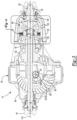
- FIG. 2 and 3 an example of an axle assembly is shown.
- the example shown in Figures 2 and 3 is primarily referenced below in the context of being the front axle assembly 14; however, it is to be understood that the front axle assembly 14 may be provided in other configurations, including but not limited to locating the interaxle differential unit outside the front axle assembly 14, by providing a drop gear configuration in which a drive gear and a driven gear provide torque from the interaxle differential unit to the drive pinion, by not routing the output shaft through a drive pinion, or combinations thereof.
- the axle assembly may include a housing assembly 30, a differential 32, a pair of axle shafts 34, an input yoke 36, an input shaft 38, a drive pinion 40, an output shaft 42, an output yoke 44, an interaxle differential unit 46, a one-way freewheel clutch 48, and an interaxle differential unit lock 50.
- the housing assembly 30 may receive various components of the axle assembly.
- the housing assembly 30 may facilitate mounting of the axle assembly to the vehicle 10.
- the housing assembly 30 may include an axle housing 60 and a differential carrier 62.
- the axle housing 60 may receive and support the axle shafts 34.
- the axle housing 60 may include a center portion 70 and at least one arm portion 72.
- the center portion 70 may be disposed proximate the center of the axle housing 60.
- the center portion 70 may define a cavity that may receive the differential 32.
- a lower region of the center portion 70 may at least partially define a sump portion that may contain lubricant. Splashed lubricant may flow down the sides of the center portion 70 and may flow over internal components of the axle assembly and collect in the sump portion.
- One or more arm portions 72 may extend from the center portion 70.
- two arm portions 72 may extend in opposite directions from the center portion 70 and away from the differential 32.
- the arm portions 72 may have substantially similar configurations.
- the arm portions 72 may each have a hollow configuration or tubular configuration that may extend around and may receive a corresponding axle shaft 34 and may help separate or isolate the axle shaft 34 from the surrounding environment.
- An arm portion 72 or a portion thereof may be integrally formed with the center portion 70 or may be separate from the center portion 70.
- the differential carrier 62 which may also be called a carrier housing, may be mounted to the center portion 70 of the axle housing 60.
- the differential carrier 62 may receive the interaxle differential unit 46 and support components of the differential 32.
- the differential carrier 62 may have one or more bearing supports 80.
- the bearing support 80 may support a roller bearing assembly that may rotatably support the differential 32.
- two bearing supports 80 may be received in the center portion 70 and may be located proximate opposite sides of the differential 32.
- the differential 32 may be disposed in the center portion 70 of the housing assembly 30.
- the differential 32 may transmit torque to the wheel assemblies 20 and permit the wheel assemblies 20 of a corresponding axle assembly to rotate at different velocities in a manner known by those skilled in the art.
- the differential 32 may have a ring gear 90 that may be fixedly mounted on a differential case 92.
- the ring gear 90 and the differential case 92 may be rotatable about a differential axis 100.
- the differential case 92 may receive differential gears that may be operatively connected to the axle shafts 34. Torque that is provided to the drive pinion 40 may be transmitted to the ring gear 90.
- the differential 32 may receive torque via the ring gear 90 and provide torque to the axle shafts 34 and to its associated wheel assemblies 20.
- the axle shafts 34 may be configured to transmit torque from an associated differential to corresponding wheel assemblies 20.
- two axle shafts 34 may be provided such that each axle shaft 34 extends through a different arm portion 72 of axle housing 60.
- the axle shafts 34 may extend along and may be rotatable about the differential axis 100.
- the input yoke 36 may facilitate coupling of an axle assembly to the torque source 18.
- the input yoke 36 may be mounted on the input shaft 38.
- the input yoke 36 may have an opening that receives the input shaft 38 and may be secured to the input shaft 38 with a fastener, such as a nut.
- the input shaft 38 may extend along and may be configured to rotate about a first axis 110.
- the input shaft 38 may be rotatably supported at least one roller bearing assembly, which may be referred to as an input bearing, that may be disposed on the differential carrier 62.
- the input shaft 38 may be part of the interaxle differential unit 46 or may be operatively connected to the interaxle differential unit 46.
- the input shaft 38 may be integrally formed with a case of the interaxle differential unit 46 or may be provided as a separate component that is fixedly coupled to the case in one or more embodiments.
- the input shaft 38 may be connected to or may have an enlarged cup portion at an end that is disposed opposite the input yoke 36.
- the cup portion may be part of the case of the interaxle differential unit 46 and may at least partially define a cavity that may receive components of the interaxle differential unit 46.
- the first axis 110 may be disposed at any suitable angle with respect to the differential axis 100, such as in a nonparallel relationship, at an oblique angle, or substantially perpendicular to the differential axis 100.
- the drive pinion 40 may provide torque to the differential 32.
- the drive pinion 40 may extend along and may be configured to rotate about the first axis 110.
- the drive pinion 40 may be rotatably supported by one or more roller bearing assemblies 112 that may be disposed on the differential carrier 62.
- the drive pinion 40 may include a shaft portion 120 and a gear portion 122.
- the shaft portion 120 may extend from the interaxle differential unit 46 to the gear portion 122.
- the shaft portion 120 may at least partially define a passage through which the output shaft 42 may extend.
- the shaft portion 120 may also include an end portion 130 and a threaded portion 132.
- the end portion 130 may extend from a distal end of the shaft portion 120 that may be disposed opposite the gear portion 122.
- the end portion 130 may have an exterior circumferential surface that may extend in an axial direction from the distal end of the shaft portion 120 toward or to the threaded portion 132.
- the end portion 130 may support one or more one-way freewheel clutches 48, which in turn may support a gear of the interaxle differential unit 46 as will be discussed in more detail below.
- the end portion 130 may have a smaller diameter than the threaded portion 132.
- the threaded portion 132 may be axially positioned between the end portion 130 and the gear portion 122.
- the threaded portion 132 may extend around the first axis 110.
- the thread or threads of the threaded portion 132 may mate with corresponding threads of an adjuster nut 134, that may exert a preload force on the roller bearing assemblies 112 and may inhibit axial movement of at least one roller bearing assembly 112 away from the gear portion 122.
- the gear portion 122 may be disposed at an end of the shaft portion 120.
- the gear portion 122 may have a plurality of teeth that may mesh or mate with corresponding teeth on the ring gear 90.
- the output shaft 42 may extend along and may be configured to rotate about an axis, such as the first axis 110.
- the output shaft 42 may be supported by one or more roller bearings that may be disposed on the housing assembly 30, such as one or more output bearings that may be disposed near or at an opposite end of the housing assembly 30 from the input bearing.
- the output shaft 42 may extend through the drive pinion 40 and may extend at least partially through the interaxle differential unit 46 as will be discussed in more detail below.
- the output shaft 42 may be operatively connected to or coupled to the interaxle differential unit 46 at a first end.
- the output shaft 42 may be fixedly coupled a gear of the interaxle differential unit 46 as will be discussed in more detail below.
- the output shaft 42 may be fixedly coupled to the output yoke 44 at a second end that may be disposed opposite the first end.
- the output yoke 44 may facilitate coupling of the output shaft 42 to the rear axle assembly 16.
- the output yoke 44 may be coupled to a connecting shaft, such as the prop shaft 22.
- the output yoke 44 may be mounted on the output shaft 42.
- the output yoke 44 may have an opening that receives the output shaft 42 may be secured to the output shaft 42 with a fastener like a nut.
- the interaxle differential unit 46 may be operatively connectable with the front axle assembly 14 and the rear axle assembly 16.
- the interaxle differential unit 46 may compensate for speed differences between different axle assemblies, such as speed differences between the front axle assembly 14 and the rear axle assembly 16. It is contemplated that the interaxle differential unit 46 may be provided with the front axle assembly 14, the rear axle assembly 16, or at an intermediate location between the front axle assembly 14 and the rear axle assembly 16.
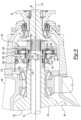
- the interaxle differential unit may be provided in various configurations. In the configuration shown in Figures 3-7 , the interaxle differential unit 46 does not include a planetary gear set. In such a configuration, the interaxle differential unit 46 may include a case 140, a first side gear 142, a second side gear 144, a spider 146, and a plurality of pinion gears 148. The interaxle differential unit 46 may also include one or more thrust bearings 150, a stabilizer bearing 152, or combinations thereof.
- the case 140 may be configured to receive components of the interaxle differential unit 46.
- the case 140 may be rotatable about the first axis 110.
- the case 140 may include a first case portion 160 and a second case portion 162 that may cooperate to at least partially define a cavity.
- the cavity may at least partially receive the first side gear 142, second side gear 144, spider 146, pinion gears 148, thrust bearing 150, and the stabilizer bearing 152.
- the first case portion 160 may extend around the first axis 110 and may receive at least a portion of the interaxle differential unit 46.
- the first case portion 160 may be configured as a unitary or one piece component that includes the input shaft 38 or may be a separate component from the input shaft 38.
- the first case portion 160 may include a plurality of fastener holes 170 and a first end surface 172.
- the fastener holes 170 may be arranged around the first axis 110 and may receive a corresponding fastener 174, such as a bolt, that may fixedly couple the first case portion 160 to the second case portion 162.
- the first end surface 172 that may face toward and may engage the second case portion 162.
- the second case portion 162 may be disposed opposite the first case portion 160 and may receive at least a portion of the interaxle differential unit 46.
- the second case portion 162 may be configured as a ring that may extend around the first axis 110 and may include plurality of fastener holes that may receive a corresponding fastener 174.
- the second case portion 162 may also include a second end surface 182 and a set of teeth 184.
- the second end surface 182 may face toward and may engage the first end surface 172.
- the set of teeth 184 may be disposed at an end of the second case portion 162 that is disposed opposite the second end surface 182 and that may face away from the first case portion 160.
- the set of teeth 184 may be arranged around the first axis 110 and may extend toward the first axis 110.
- the set of teeth 184 may receive and mesh with the interaxle differential unit lock 50.
- the first case portion 160 may cooperate with the second case portion 162 to define one or more spider shaft holes 190.
- the spider shaft holes 190 may be generally disposed between the first end surface 172 of the first case portion 160 and the second end surface 182 of the second case portion 162.
- a spider shaft hole 190 may receive a shaft of the spider 146 as will be discussed in more detail below. In the configuration shown, three spider shaft holes 190 are shown; however, it is contemplated that a greater or lesser number of spider shaft holes 190 may be provided.
- the spider shaft holes 190 may be spaced apart from each other and may be arranged around the first axis 110. For example, spider shaft holes 190 may be disposed along axes that may be disposed substantially perpendicular to the first axis 110.
- the first side gear 142 may extend around the first axis 110 and the drive pinion 40.
- the first side gear 142 may have a center bore that may receive the shaft portion 120 of the drive pinion 40.
- the center bore may receive the one-way freewheel clutch 48.
- the first side gear 142 may be spaced apart from the drive pinion 40 and may be selectively rotatable with the drive pinion 40 and selectively rotatable with respect to the drive pinion 40 due to the functionality of the one-way freewheel clutch 48 as will be discussed in more detail below.
- the second side gear 144 may be disposed on the output shaft 42.
- the second side gear 144 may be extend around the first axis 110 and may have a center bore that may receive the output shaft 42.
- the center bore may include a spline that may receive and engage a corresponding spline on the output shaft 42. As such, the second side gear 144 may not rotate about the first axis 110 with respect to the output shaft 42.
- the spider 146 may be fixedly positioned with respect to the case 140 and may be rotatable with respect to the drive pinion 40.
- the spider 146 may be axially positioned in the case 140 between the first side gear 142 and the second side gear 144.
- the spider 146 may be spaced apart from and may not engage the output shaft 42.
- the spider 146 may be rotatable with respect to the output shaft 42.
- spider 146 may include an annular spider body 200, a spider hole 202, and one or more spider shafts 204.
- the annular spider body 200 may be axially positioned between the second side gear 144 and the drive pinion 40.
- the annular spider body 200 may at least partially define the spider hole 202.
- the spider hole 202 may be a through hole that may extend through the annular spider body 200.
- the output shaft 42 may extend through the spider hole 202.
- the drive pinion 40 may or may not be received in the spider hole 202.
- One or more spider shafts 204 may extend from the annular spider body 200. In the configuration shown, three spider shafts 204 are provided; however, it is contemplated that a greater or lesser number of spider shafts 204 may be provided in one or more embodiments.
- the spider shafts 204 may be integrally formed with the annular spider body 200 or may be provided as separate components that are fixed to the annular spider body 200.
- Each spider shaft 204 may extend from the annular spider body 200 in a direction that extends away from the first axis 110. For example, each spider shaft 204 may extend along a spider shaft axis that may be disposed substantially perpendicular to the first axis 110. In addition, an end of each spider shaft 204 may be received in a corresponding spider shaft hole 190 of the case 140.
- a spider shaft 204 may have a generally cylindrical configuration.
- a pinion gear 148 may be rotatably disposed on a corresponding spider shaft 204.
- Each pinion gear 148 may have teeth that may mesh with teeth on the first side gear 142 and the second side gear 144.
- the thrust bearing 150 may be disposed between the case 140 and the second side gear 144.
- the thrust bearing 150 may rotatably support the second side gear 144 with respect to the first case portion 160.
- the stabilizer bearing 152 may rotatably support the spider 146.
- the stabilizer bearing 152 may be received in the spider 146 and may have a hole that receives the drive pinion 40.
- the stabilizer bearing 152 may be axially positioned between the first side gear 142 and the second side gear 144.
- the stabilizer bearing 152 may have any suitable configuration.
- the stabilizer bearing 152 may be configured as a roller bearing assembly that may include a plurality of rolling elements that may be disposed between an inner race and an outer race.
- the stabilizer bearing 152 may be configured as a bushing that does not have rolling elements, but that permits rotation of drive pinion 40 with respect to the spider 146.
- the one-way freewheel clutch 48 may selectively couple the interaxle differential unit 46 to the drive pinion 40.
- the one-way freewheel clutch 48 may disengage a drive shaft from a driven shaft when the driven shaft rotates faster than the drive shaft.
- the one-way freewheel clutch 48 may be of any suitable type, such as a sprage clutch, ratchet clutch, or the like. In at least one configuration, at least one one-way freewheel clutch 48 may extend around and receive the drive pinion 40 and may be received in the center bore of the first side gear 142.
- the one-way freewheel clutch 48 may couple the drive pinion 40 and the first side gear 142 such that they may rotate together in one rotational direction and such that the drive pinion 40 and the first side gear 142 may not rotate together in a second rotational direction that is opposite the first rotational direction. Moreover, the one-way freewheel clutch 48 may accommodate a speed difference between the drive pinion 40 and the first side gear 142 when they are rotating in the same rotational direction as will be discussed in more detail below.
- an example of an interaxle differential unit lock 50 is shown.
- the interaxle differential unit lock 50 may selectively unlock and lock the interaxle differential unit 46.
- the case 140 and the first side gear 142 may be decoupled when the interaxle differential unit lock 50 is in an unlocked position as is shown in Figure 4 such that the case 140 may be rotatable with respect to the first side gear 142.
- the case 140 and the first side gear 142 may be coupled when the interaxle differential unit lock 50 is in a locked position as is shown in Figure 5 such that the case 140 and the first side gear 142 may be rotatable together.
- the interaxle differential unit lock 50 may be of any suitable type, such as a clutch like a disc clutch, cone clutch, spline clutch, face clutch, or the like. In the configuration shown in Figures 4 , 5 and 7 , the interaxle differential unit lock 50 is depicted as a disc clutch that may include a disc pack 210 and an actuator 212.
- the disc pack 210 may be received in the second case portion 162 and may have one or more stationary discs 220 and one or more friction discs 222.
- the stationary discs 220 may be mounted to the second case portion 162.
- the stationary discs 220 may have protrusions or teeth that may mesh with the set of teeth 184 of the second case portion 162 and may be rotatable with the second case portion 162.
- the friction discs 222 may be mounted to the first side gear 142 such that they are rotatable with the first side gear 142.
- Each friction disc 222 may be disposed adjacent to a stationary disc 220.
- the stationary discs 220 may be spaced apart from each other such that a friction disc 222 is disposed between adjacent stationary discs 220.
- the actuator 212 may be configured to move in an axial direction between a retracted position and an extended position to unlock and lock the interaxle differential unit lock 50.
- the actuator 212 may be of any suitable type, such as a mechanical actuator, electrical actuator, pneumatic actuator, hydraulic actuator, electromechanical actuator, or the like.
- the actuator 212 is depicted as a piston 230 that may be received in a piston housing 232 that may be mounted to the case 140.
- the actuator 212 is shown in a retracted position in which the actuator 212 may be disposed proximate the disc pack 210 such that the stationary discs 220 and the friction discs 222 may be free to rotate with respect to each other and the interaxle differential unit 46 is unlocked.
- the actuator 212 is shown in an extended position in which the actuator 212 is moved to the right with respect to the position shown in Figure 4 to exert force against the stationary discs 220 and the friction discs 222 to deflect or urge the stationary discs 220 and the friction discs 222 into frictional engagement, which may deflect or compress the stationary discs 220 and the friction discs 222 toward the first case portion 160 and toward or against a side of the second case portion 162.
- the friction discs 222 may not be rotatable with respect to the stationary discs 220 when sufficient force is exerted by the actuator 212, thereby locking the interaxle differential unit 46.
- a mechanical lock such as a collar, may be provided with the interaxle differential unit lock 50 in addition to a disc pack 210 to allow the interaxle differential unit 46 to be held in the locked position by the mechanical lock rather than relying solely on the disc pack 210.
- the rear axle assembly 16 may have a similar configuration as the front axle assembly 14.
- components of the rear axle assembly 16 that are the same or substantially similar in structure and/or function to components of the front axle assembly 14 are designated with common reference numbers followed by an apostrophe or prime symbol ( ⁇ ).
- the rear axle assembly 16 may have a housing assembly 30', a differential 32', a pair of axle shafts 34', an input yoke 36', an input shaft 38', and a drive pinion 40'.
- the differential 32' may have a ring gear 90' that may be rotatable about a differential axis 100'.
- the rear axle assembly 16 may not include an output shaft, an output yoke, an interaxle differential unit, a one-way freewheel clutch, an interaxle differential unit lock, or combinations thereof.
- the front axle assembly 14 and the rear axle assembly 16 may have different gear ratios. More specifically, the drive pinion 40 and the ring gear 90 of the front axle assembly 14 may cooperate to provide a gear ratio for the front axle assembly 14 while the drive pinion 40' and the ring gear 90' of the rear axle assembly 16 may cooperate to provide a gear ratio for the rear axle assembly 16.
- the gear ratio of the front axle assembly 14 may be greater than the gear ratio of the rear axle assembly 16 or vice versa.
- the front axle assembly 14 may have a gear ratio of 2.47 while the rear axle assembly 16 may have a gear ratio of 3.7 or vice versa.
- axle assemblies that may be provided with the drive axle system 12 may be referred to as a "first axle assembly” and a “second axle assembly” since either the front axle assembly 14 or the rear axle assembly 16 may have the higher gear ratio.
- the first axle assembly may be either the front axle assembly 14 or the rear axle assembly 16 while the second axle assembly may be the axle assembly that is not the first axle assembly, and thus may also be other of the front axle assembly 14 or the rear axle assembly 16.
- the one-way freewheel clutch 48 may be provided with the axle assembly that has the higher numerical gear ratio.
- the one-way freewheel clutch 48 will allow torque to be transmitted to the axle assembly having the lower numerical gear ratio when the interaxle differential unit is locked.
- the one-way freewheel clutch 48 may be "overrun” by the rotation of the wheels of the front axle assembly 14 (which may be connected via the axle shafts 34, differential 32, and drive pinion 40 of the front axle assembly 14) and forward propulsion torque may be directed to the faster (i.e., lower gear ratio) rear axle assembly 16.
- the one-way freewheel clutch may be "overrun” by the rotation of the wheels of the rear axle assembly 16 and forward propulsion torque may be directed to the faster (i.e., lower gear ratio) front axle assembly 14.
- Torque may be transmitted to the front axle assembly 14 and the rear axle assembly 16 when the interaxle differential unit 46 is unlocked.
- the side gears of the interaxle differential unit 46 may rotate at different speeds but with substantially the same torque when the interaxle differential unit 46 is unlocked.
- the front axle assembly 14 has a higher (slower) gear ratio than the rear axle assembly 16
- forward propulsion torque may be transmitted to the rear axle assembly 16 as well as the front axle assembly 14 when the interaxle differential unit 46 is unlocked.
- the rear axle assembly 16 has a higher (slower) gear ratio than the front axle assembly 14
- forward propulsion torque may be transmitted to the front axle assembly 14 as well as the rear axle assembly 16 when the interaxle differential unit 46 is unlocked.
- the drive axle system 12 may operate in a reverse direction to provide reverse propulsion torque when the interaxle differential unit 46 is locked rather than unlocked.
- the reverse propulsion torque and traction parameters would be dictated by the axle assembly having the lower numerical gear ratio. No meaningful torque would be transmitted in reverse through the axle assembly having the higher numerical gear ratio.
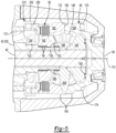
- FIG. 8-12 another configuration of an interaxle differential unit 46' is shown.
- This configuration of an interaxle differential unit 46' may be provided in place of the interaxle differential unit 46 previously discussed. As such, the discussion found in the four preceding paragraphs is also applicable to the interaxle differential unit 46' shown in Figures 8-12 .
- the interaxle differential unit 46' may compensate for speed and torque differences between different drive axle assemblies, such as speed differences between the front axle assembly 14 and a rear axle assembly 16 as previously discussed.
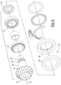
- the interaxle differential unit 46' includes a planetary gear set that may include a sun gear 300, at least one planet gear 302, a planetary ring gear 304, and a planet gear carrier 306.
- the sun gear 300 may be disposed proximate the center of the planetary gear set and may be rotatable about the first axis 110.
- the sun gear 300 may extend through the planet gear carrier 306 and partially through the planetary ring gear 304.
- the sun gear 300 may be configured as a hollow tubular body that may include a first end surface 310, a second end surface 312, a sun gear hole 314, a spacer portion 316, a first set of sun gear teeth 318, and a second set of sun gear teeth 320.
- the first end surface 310 may be disposed at an end of the sun gear 300 that may face toward the drive pinion 40.
- the first end surface 310 may be disposed outside the planetary ring gear 304 and the planet gear carrier 306.
- the second end surface 312 may be disposed at an end of the sun gear 300 that may face toward the input shaft 38 and the planetary ring gear 304. As such, the second end surface 312 may be disposed opposite the first end surface 310. The second end surface 312 may be disposed inside the planetary ring gear 304.
- the sun gear hole 314 may extend from the first end surface 310 to the second end surface 312.
- the sun gear hole 314 may extend along and may be centered about the first axis 110.
- the drive pinion 40 may extend into or through the sun gear hole 314 and may be spaced apart from the sun gear 300.
- the output shaft 42 may extend through the sun gear hole 314.
- the sun gear hole 314 may receive one or more one-way freewheel clutches 48.
- the one-way freewheel clutches 48 may receive the drive pinion 40 as previously described and may selectively couple the drive pinion 40 and the sun gear 300.
- two one-way freewheel clutches 48 are shown; however, a greater or lesser number may be provided.
- the first set of sun gear teeth 318 may be disposed opposite the sun gear hole 314 and may be arranged around the sun gear hole 314 in a repeating arrangement.
- the sun gear teeth 318 may extend radially away from the first axis 110 and may extend axially in a direction that is substantially parallel to the first axis 110.
- the first set of sun gear teeth 318 may be disposed closer to the first end surface 310 than the second set of sun gear teeth 320.
- the first set of sun gear teeth 318 may extend axially from the first end surface 310 toward the second set of sun gear teeth 320.
- the first set of sun gear teeth 318 may be disposed opposite a first one-way freewheel clutch 48.
- the second set of sun gear teeth 320 may be disposed opposite the sun gear hole 314 and may be arranged around the sun gear hole 314 in a repeating arrangement.
- the sun gear teeth 320 may extend radially away from the first axis 110 and may extend axially in a direction that is substantially parallel to the first axis 110.
- the second set of sun gear teeth 320 may be disposed closer to the second end surface 312 than the first set of sun gear teeth 318.
- the second set of sun gear teeth 320 may extend axially from the second end surface 312 toward the first set of sun gear teeth 318.
- the second set of sun gear teeth 320 may have a larger outside diameter than the first set of sun gear teeth 318.
- the second set of sun gear teeth 320 may be disposed opposite a second one-way freewheel clutch 48.
- At least one planet gear 302 may be rotatably disposed between the sun gear 300 and the planetary ring gear 304.
- eight planet gears 302 are depicted; however, it is contemplated that a greater or lesser number of planet gears 302 may be provided.
- the planet gears 302 may be spaced apart from each other and each planet gear 302 may be rotatable about a different planet gear axis 330.
- the planet gear axes 330 may be disposed substantially parallel to the first axis 110.
- Each planet gear 302 may have a hole and a set of teeth. The hole may be a through hole that may extend through the planet gear 302.
- the hole may receive a pin 332 about which the planet gear 302 may rotate.
- the pin 332 may be fixedly mounted to the planet gear carrier 306.
- a bearing may also be received in the hole and may rotatably support the planet gear 302 on a corresponding pin 332.
- the set of teeth may be disposed opposite the hole. The set of teeth may mesh with the second set of sun gear teeth 320 and teeth on the planetary ring gear 304.
- the planetary ring gear 304 may extend around the first axis 110 and may receive the planet gears 302. In addition, the planetary ring gear 304 may be selectively rotatable with respect to the drive pinion 40. In at least one configuration, the planetary ring gear 304 may include a mounting hub 340, a first flange 342, and a second flange 344.
- the mounting hub 340 may facilitate coupling or mounting of the planetary ring gear 304 to the output shaft 42.
- the mounting hub 340 may be axially positioned between the drive pinion 40 and the input shaft 38 and may define a hole that may receive the output shaft 42.
- the mounting hub 340 may have a mounting hub hole 350 and a mounting hub spline 352.
- the mounting hub hole 350 may extend along and may be centered about the first axis 110.
- the mounting hub spline 352 may be disposed in the mounting hub hole 350 and may facilitate mounting of the planetary ring gear 304 to the output shaft 42.
- the mounting hub spline 352 may mesh or mate with a corresponding spline or set of splines on the output shaft 42 such that the planetary ring gear 304 and the output shaft 42 are rotatable together about the first axis 110.
- the first flange 342 may extend radially outward from the mounting hub 340 to the second flange 344.
- the second flange 344 may extend from an end of the first flange 342. For instance, the second flange 344 may extend toward and may be spaced apart from the planet gear carrier 306. A set of teeth 346 may be provided on the second flange 344 that may extend toward the first axis 110 and may mesh with teeth on the planet gears 302.
- the planet gear carrier 306 may be rotatable about the first axis 110.
- the planet gear carrier 306 may be fixedly coupled to the cup portion of the input shaft 38. As such, the input shaft 38 and the planet gear carrier 306 may rotate together about the first axis 110.
- the planet gear carrier 306 may support the pins 332.
- the pins 332 may extend from a side of the planet gear carrier 306 that faces toward the first flange 342 of the planetary ring gear 304.
- the planet gear carrier 306 may include a planet carrier hole 360 and a set of planet carrier teeth 362.
- the planet carrier hole 360 may extend around the first axis 110 and may receive the sun gear 300 such that the planet gear carrier 306 is spaced apart from the sun gear 300.
- the set of planet carrier teeth 362 may be disposed in the planet carrier hole 360 and may extend toward the first axis 110.
- the planet carrier teeth 362 may be arranged in a repeating arrangement around the first axis 110 and may extend axially in a direction that is substantially parallel to the first axis 110.
- the interaxle differential unit lock 50 may selectively mesh or mate with the set of planet carrier teeth 362 as will be discussed in more detail below.
- the set of planet carrier teeth 362 may be disposed closer to the first axis 110 than the planet gear axes 330.
- the interaxle differential unit lock 50 may be movable in an axial direction or in a direction that extends along the first axis 110 between an unlocked position and a locked position as previously discussed.
- the interaxle differential unit lock 50 may have any suitable configuration as previously discussed.
- the interaxle differential unit lock 50 is configured as a collar that may be generally ring-shaped and may include a collar hole 370, a set of internal teeth 372, a set of external teeth 374, and a collar groove 376.
- the collar hole 370 may be a through hole that may extend through the interaxle differential unit lock 50 and extend around the first axis 110.
- the collar hole 370 may receive the drive pinion 40 and may selectively receive the sun gear 300.
- the set of internal teeth 372 may be disposed in the collar hole 370.
- the internal teeth 372 may extend toward the first axis 110 and may mesh or mate with corresponding teeth 378 on the drive pinion 40, which are is best shown in Figure 12 , or teeth on an intervening ring that may receive the drive pinion 40.
- the mating teeth may allow the interaxle differential unit lock 50 to move in an axial direction or along the first axis 110 while inhibiting rotation of the interaxle differential unit lock 50 about the first axis 110 with respect to the drive pinion 40.
- the set of external teeth 374 may be disposed opposite the collar hole 370 and the set of internal teeth 372.
- the external teeth 374 may extend away from the first axis 110 and may selectively mesh or mate with the set of planet carrier teeth 362.
- the collar groove 376 may face away from the first axis 110 and may extend around the first axis 110.
- the collar groove 376 may receive a linkage, such as a shift fork 380, that may operatively connect the interaxle differential unit lock 50 to the actuator 212.
- the actuator 212 may move the interaxle differential unit lock 50 between the unlocked position and the locked position.
- the interaxle differential unit lock 50 is shown in the unlocked position.
- the set of internal teeth 372 of the interaxle differential unit lock 50 may mesh or mate with teeth 378 of the drive pinion 40 or that are fixedly positioned with respect to the drive pinion 40 and with the first set of sun gear teeth 318.
- the set of external teeth 374 may be spaced apart from and may not mesh or mate with the planet carrier teeth 362 when the interaxle differential unit lock 50 is in the unlocked position.
- the sun gear 300 and the drive pinion 40 may rotate together about the first axis 110. Torque may be transmitted to the front axle assembly 14 and the rear axle assembly 16 when the interaxle differential unit lock 50 is in the unlocked position.
- torque may be transmitted from the interaxle differential unit 46' to the drive pinion 40 via the sun gear 300 and the interaxle differential unit lock 50 while torque may be transmitted from the interaxle differential unit 46' to the output shaft 42 via the planetary ring gear 304 and planet gears 302.
- the planetary gear set of the interaxle differential unit 46' may allow the drive pinion 40 and the output shaft 42 to rotate at different speeds about the first axis 110.
- the interaxle differential unit lock 50 is shown in the locked position.
- the set of internal teeth 372 of the interaxle differential unit lock 50 may mesh or mate with the first set of sun gear teeth 318 but may not mesh or mate with teeth 378 of the drive pinion 40 or that are fixedly positioned with respect to the drive pinion 40.
- the set of external teeth 374 may mesh or mate with the planet carrier teeth 362 when the interaxle differential unit lock 50 is in the locked position.
- the sun gear 300 may rotate with the planet gear carrier 306 about the first axis 110 and may be rotatable about the first axis 110 independently of the drive pinion 40. Accordingly, torque may not be transmitted between the sun gear 300 and the drive pinion 40.
- input torque that is provided to the input shaft 38 may cause the sun gear 300 to rotate about the first axis 110 with respect to the drive pinion 40 and torque may not be transmitted from the drive pinion 40 to the differential 32 and its associated axle shafts 34 and wheel assemblies 20. Torque may be transmitted between the input shaft 38 and the output shaft 42 via the interaxle differential unit 46 when the interaxle differential unit lock 50 is in the locked position. As an example, input torque that is provided to the input shaft 38 may be transmitted to the output shaft 42 via the planet gear carrier 306, planet gears 302, and the planetary ring gear 304.
- a control system 400 may monitor and/or control operation of the axle system.
- the control system 400 may include one or more electronic controllers that may monitor and/or control various components of the drive axle system 12.
- the control system 400 may be configured to control actuation of the interaxle differential unit lock 50 to operatively connect the drive pinion 40 to the torque source 18 such that torque may be transmitted from the torque source 18 to a differential and to operatively disconnect the drive pinion 40 from the torque source 18 such that torque may not be transmitted from the torque source 18 to a differential.
Landscapes
- Engineering & Computer Science (AREA)
- Mechanical Engineering (AREA)
- Chemical & Material Sciences (AREA)
- Combustion & Propulsion (AREA)
- Transportation (AREA)
- General Engineering & Computer Science (AREA)
- Retarders (AREA)
Claims (15)
- Antriebsachsensystem (12), Folgendes umfassend:eine erste Achsenanordnung (14), die ein erstes Antriebsritzel (40) und eine erste Differentialanordnung (32) mit einem ersten Tellerrad (90) aufweist, wobei das erste Tellerrad (90) und das erste Antriebsritzel (40) zusammenwirken, um ein erstes Übersetzungsverhältnis vorzusehen;eine zweite Achsenanordnung (16), die mit der ersten Achsenanordnung (14) funktional verbunden ist, wobei die zweite Achsenanordnung (16) ein zweites Antriebsritzel (40') und eine zweite Differentialanordnung (32') mit einem zweiten Tellerrad (90) aufweist, wobei das zweite Antriebsritzel (40') und das zweite Tellerrad (90) zusammenwirken, um ein zweites Übersetzungsverhältnis vorzusehen, das sich vom ersten Übersetzungsverhältnis unterscheidet;dadurch gekennzeichnet, dasseine Zwischenachsendifferentialeinheit (46, 46') dazu ausgelegt ist, die erste Achsenanordnung (14) und die zweite Achsenanordnung (16) funktional miteinander zu verbinden; undeine Freilaufkupplung (48), die ein Drehmoment zwischen der ersten Achsenanordnung (14) und der zweiten Achsenanordnung (16) überträgt, wenn die Zwischenachsendifferentialeinheit (46, 46') entsperrt ist, und die ein Drehmoment zur ersten Achsenanordnung (14) oder zur zweiten Achsenanordnung (16) überträgt, wenn die Zwischenachsendifferentialeinheit (46, 46') gesperrt ist.
- Antriebsachsensystem nach Anspruch 1, wobei die Zwischenachsendifferentialeinheit (46, 46') ein Drehmoment zur ersten Achsenanordnung (14), jedoch nicht zur zweiten Achsenanordnung (16) überträgt, wenn die Zwischenachsendifferentialeinheit (46, 46') gesperrt ist und das erste Übersetzungsverhältnis kleiner ist als das zweite Übersetzungsverhältnis.
- Antriebsachsensystem nach einem der vorstehenden Ansprüche, wobei die Zwischenachsendifferentialeinheit (46, 46') ein Drehmoment zur zweiten Achsenanordnung (16), jedoch nicht zur ersten Achsenanordnung (14) überträgt, wenn die Zwischenachsendifferentialeinheit (46, 46') gesperrt ist und das zweite Übersetzungsverhältnis kleiner ist als das erste Übersetzungsverhältnis.
- Antriebsachsensystem nach einem der vorstehenden Ansprüche, wobei die erste Differentialanordnung (32) um eine erste Differentialachse (100) drehbar ist, die zweite Differentialanordnung (32') um eine zweite Differentialachse (100') drehbar ist und die Freilaufkupplung (48) ein Drehmoment zwischen der ersten Achsenanordnung (14) und der zweiten Achsenanordnung (16) überträgt, sodass die erste Differentialanordnung (32) in eine erste Drehrichtung um die erste Differentialachse (100) drehbar ist und die zweite Differentialanordnung (32') in die erste Drehrichtung um die zweite Differentialachse (100') drehbar ist, wenn die Zwischenachsendifferentialeinheit (46, 46') entsperrt ist.
- Antriebsachsensystem nach einem der vorstehenden Ansprüche, wobei die erste Differentialanordnung (32) um eine erste Differentialachse (100) drehbar ist, die zweite Differentialanordnung (32') um eine zweite Differentialachse (100') drehbar ist und die Freilaufkupplung (48) ein Drehmoment zur ersten Achsenanordnung (14) überträgt, um die erste Differentialanordnung (32) in eine der ersten Drehrichtung entgegengesetzte zweite Drehrichtung um die erste Differentialachse (100) zu drehen, wenn das erste Übersetzungsverhältnis kleiner ist als das zweite Übersetzungsverhältnis und die Zwischenachsendifferentialeinheit (46, 46') gesperrt ist, vorzugsweise wobei die Freilaufkupplung (48) ein Drehmoment zur zweiten Achsenanordnung (16) überträgt, um die zweite Differentialanordnung (32') in eine der ersten Drehrichtung entgegengesetzte zweite Drehrichtung um die zweite Differentialachse (100`) zu drehen, wenn das zweite Übersetzungsverhältnis kleiner ist als das erste Übersetzungsverhältnis und die Zwischenachsendifferentialeinheit (46, 46') gesperrt ist.
- Antriebsachsensystem nach einem der vorstehenden Ansprüche, wobei die Zwischenachsendifferentialeinheit (46, 46') in der ersten Achsenanordnung (14) angeordnet ist, wobei die Zwischenachsendifferentialeinheit (46, 46') und das erste Antriebsritzel (40) vorzugsweise um eine erste Drehachse (110) drehbar sind.
- Antriebsachsensystem nach einem der vorstehenden Ansprüche, wobei die Freilaufkupplung (48) mit der Zwischenachsendifferentialeinheit (46, 46') versehen ist.
- Antriebsachsenanordnung nach einem der vorstehenden Ansprüche, wobei die Zwischenachsendifferentialeinheit (46) Folgendes umfasst:ein erstes Achswellenkegelrad (142), welches das erste Antriebsritzel (40) aufnimmt;ein zweites Achswellenkegelrad (144), das an einer Ausgangswelle (42) fixiert ist; undein Ausgleichskegelrad (148), das in das erste Achswellenkegelrad (142) und das zweite Achswellenkegelrad (144) eingreift; undwobei die Freilaufkupplung (48) das erste Antriebsritzel (40) aufnimmt und in dem ersten Achswellenkegelrad (142) aufgenommen ist.
- Antriebsachsensystem nach Anspruch 8, wobei die Freilaufkupplung (48) das erste Achswellenkegelrad (142) derart mit dem ersten Antriebsritzel (40) koppelt, dass das erste Achswellenkegelrad (142) und das Ausgleichskegelrad (148) zusammen drehbar sind, wenn auf das erste Achswellenkegelrad (142) ein Drehmoment in eine erste Richtung aufgebracht wird, und wobei die Freilaufkupplung (48) die Drehung des ersten Achswellenkegelrads (142) in Bezug zum ersten Antriebsritzel (40) zulässt, wenn ein Drehmoment in eine der ersten Richtung entgegengesetzte zweite Richtung aufgebracht wird.
- Antriebsachsensystem nach Anspruch 8 oder Anspruch 9, wobei die Zwischenachsendifferentialeinheit (46) ein Gehäuse (140) umfasst, welches das erste Achswellenkegelrad (142), das zweite Achswellenkegelrad (144) und das Ausgleichskegelrad (148) aufnimmt, und wobei die Zwischenachsendifferentialeinheit (46) ferner eine Zwischenachsendifferentialsperre (50) umfasst, welche das erste Achswellenkegelrad (142) derart mit dem Gehäuse (140) koppelt, dass das erste Achswellenkegelrad (142) und das Gehäuse (140) zusammen drehbar sind, wenn sich die Zwischenachsendifferentialsperre (50) in einer Sperrposition befindet, und das Gehäuse (140) in Bezug zum ersten Achswellenkegelrad (142) drehbar ist, wenn sich die Zwischenachsendifferentialsperre (50) in einer Entsperrposition befindet, vorzugsweise wobei die Freilaufkupplung (48) im Gehäuse (140) aufgenommen ist und/oder die Zwischenachsendifferentialsperre (50) ein Scheibenpaket (210) umfasst, das sich um das erste Achswellenkegelrad (142) herum erstreckt und in dem Gehäuse (140) aufgenommen ist.
- Antriebsachsenanordnung nach einem der Ansprüche 1 bis 7, wobei die Zwischenachsendifferentialeinheit (46') Folgendes umfasst:einen Planetenträger (306), der mit einer Eingangswelle (38) um eine Drehachse (110) drehbar ist;ein Planetenhohlrad (304), das mit einer Ausgangswelle (42) um die Drehachse (110) drehbar ist;ein Sonnenrad (300), welches das erste Antriebsritzel (40) aufnimmt; undein Planetenrad (302), das drehbar am Planetenträger (306) positioniert ist und in das Planetenhohlrad (304) und das Sonnenrad (300) eingreift; undwobei die Freilaufkupplung (48) im Sonnenrad (300) aufgenommen ist, vorzugsweise wobei die Freilaufkupplung (48) in dem Planetenträger (306) aufgenommen ist.
- Antriebsachsensystem nach Anspruch 11, wobei die Freilaufkupplung (48) das erste Antriebsritzel (40) aufnimmt.
- Antriebsachsensystem nach Anspruch 11 oder Anspruch 12, wobei die Freilaufkupplung (48) das Sonnenrad (300) derart mit dem ersten Antriebsritzel (40) koppelt, dass das Sonnenrad (300) und das erste Antriebsritzel (40) zusammen drehbar sind, wenn auf das Sonnenrad (300) in eine erste Richtung ein Drehmoment aufgebracht wird, und wobei die Freilaufkupplung (48) die Drehung des Sonnenrads (300) in Bezug zum ersten Antriebsritzel (40) zulässt, wenn ein Drehmoment in eine der ersten Richtung entgegengesetzte zweite Richtung aufgebracht wird.
- Antriebsachsenanordnung nach einem der Ansprüche 11 bis 13, wobei die Zwischenachsendifferentialeinheit (46') eine Zwischenachsendifferentialsperre (50) umfasst, welche das Sonnenrad (300) selektiv mit dem Planetenträger (306) koppelt, sodass das Sonnenrad (300) und der Planetenträger (306) zusammen drehbar sind, wenn sich die Zwischenachsendifferentialsperre (50) in einer Sperrposition befindet, und wobei der Planetenträger (306) in Bezug zum Sonnenrad (300) drehbar ist, wenn sich die Zwischenachsendifferentialsperre (50) in einer Entsperrposition befindet.
- Antriebsachsensystem nach einem der Ansprüche 11 bis 14, wobei eine zweite Freilaufkupplung (48) im Sonnenrad (300) aufgenommen ist und das Sonnenrad (300) einen Abstandhalterabschnitt (316) aufweist, der axial zwischen der Freilaufkupplung (48) und zweiten Freilaufkupplung (48) positioniert ist.
Applications Claiming Priority (1)
| Application Number | Priority Date | Filing Date | Title |
|---|---|---|---|
| US16/827,102 US11254206B2 (en) | 2020-03-23 | 2020-03-23 | Drive axle system |
Publications (2)
| Publication Number | Publication Date |
|---|---|
| EP3885177A1 EP3885177A1 (de) | 2021-09-29 |
| EP3885177B1 true EP3885177B1 (de) | 2024-03-06 |
Family
ID=74194678
Family Applications (1)
| Application Number | Title | Priority Date | Filing Date |
|---|---|---|---|
| EP21152727.0A Active EP3885177B1 (de) | 2020-03-23 | 2021-01-21 | Antriebsachsensystem |
Country Status (3)
| Country | Link |
|---|---|
| US (1) | US11254206B2 (de) |
| EP (1) | EP3885177B1 (de) |
| BR (1) | BR102021005463A2 (de) |
Families Citing this family (3)
| Publication number | Priority date | Publication date | Assignee | Title |
|---|---|---|---|---|
| US11602989B2 (en) | 2021-06-21 | 2023-03-14 | Arvinmeritor Technology, Llc | Axle assembly having an interaxle differential unit |
| US11708884B2 (en) | 2021-07-02 | 2023-07-25 | Arvinmeritor Technology, Llc | Axle assembly having an interaxle differential unit |
| US11698123B1 (en) | 2022-07-25 | 2023-07-11 | Arvinmeritor Technology, Llc | Axle assembly having an interaxle differential unit |
Family Cites Families (10)
| Publication number | Priority date | Publication date | Assignee | Title |
|---|---|---|---|---|
| GB1210964A (en) | 1968-09-05 | 1970-11-04 | Vauxhall Motors Ltd | Differential drive arrangements |
| US5937980A (en) | 1997-02-24 | 1999-08-17 | Dana Corporation | Bi-directional one-way clutch |
| JP2001180319A (ja) * | 1999-12-21 | 2001-07-03 | Kanzaki Kokyukoki Mfg Co Ltd | 多輪駆動車両 |
| US8523738B2 (en) | 2011-01-21 | 2013-09-03 | Dana Heavy Vehicle Systems Group, Llc | Method of shifting a tandem drive axle having an inter-axle differential |
| US9816603B2 (en) * | 2015-09-11 | 2017-11-14 | Arvinmeritor Technology, Llc | Axle assembly with interaxle differential lubrication |
| US10001201B2 (en) | 2016-11-09 | 2018-06-19 | Arvinmeritor Technology, Llc | Axle assembly with interaxle differential support |
| US10369885B2 (en) | 2017-10-17 | 2019-08-06 | Arvinmeritor Technology, Llc | Axle assembly having a gear reduction unit and an interaxle differential unit |
| US10364872B2 (en) | 2017-10-17 | 2019-07-30 | Arvinmeritor Technology, Llc | Axle assembly having a gear reduction unit and an interaxle differential unit |
| US10703202B2 (en) | 2018-02-12 | 2020-07-07 | Arvinmeritor Technology, Llc | Drive axle assembly with clutch collar |
| US10591037B2 (en) | 2018-08-09 | 2020-03-17 | Arvinmeritor Technology, Llc | Drive axle system having a planetary interaxle differential unit |
-
2020
- 2020-03-23 US US16/827,102 patent/US11254206B2/en active Active
-
2021
- 2021-01-21 EP EP21152727.0A patent/EP3885177B1/de active Active
- 2021-03-23 BR BR102021005463-8A patent/BR102021005463A2/pt unknown
Also Published As
| Publication number | Publication date |
|---|---|
| EP3885177A1 (de) | 2021-09-29 |
| US11254206B2 (en) | 2022-02-22 |
| US20210291644A1 (en) | 2021-09-23 |
| BR102021005463A2 (pt) | 2021-10-05 |
Similar Documents
| Publication | Publication Date | Title |
|---|---|---|
| US10571003B2 (en) | Axle assembly having a gear reduction unit and an interaxle differential unit | |
| EP3385106B1 (de) | Achsanordnung mit mehreren kupplungskragen | |
| US10369885B2 (en) | Axle assembly having a gear reduction unit and an interaxle differential unit | |
| EP3885177B1 (de) | Antriebsachsensystem | |
| US9457655B2 (en) | Drive axle system having a clutching device | |
| EP3597467B1 (de) | Achsanordnung mit einer untersetzungseinheit und einer zwischenachsdifferenzialeinheit | |
| EP3575120B1 (de) | Antriebsachsenanordnung mit kupplungsmuffe | |
| EP3372434A1 (de) | Achsaggregat mit einem antriebsritzelstützlager und montageverfahren | |
| CN113059960B (zh) | 具有转子轴承组件的车桥组件 | |
| EP3608143B1 (de) | Antriebsachssystem mit einer planetenzwischenachsdifferentialeinheit | |
| CN110822033B (zh) | 控制驱动车桥系统的方法 | |
| US11859718B1 (en) | Axle assembly having a shift collar | |
| EP4108494A1 (de) | Achsaggregat, das eine differenzialeinheit zwischen den achsen aufweist |
Legal Events
| Date | Code | Title | Description |
|---|---|---|---|
| PUAI | Public reference made under article 153(3) epc to a published international application that has entered the european phase |
Free format text: ORIGINAL CODE: 0009012 |
|
| STAA | Information on the status of an ep patent application or granted ep patent |
Free format text: STATUS: THE APPLICATION HAS BEEN PUBLISHED |
|
| AK | Designated contracting states |
Kind code of ref document: A1 Designated state(s): AL AT BE BG CH CY CZ DE DK EE ES FI FR GB GR HR HU IE IS IT LI LT LU LV MC MK MT NL NO PL PT RO RS SE SI SK SM TR |
|
| STAA | Information on the status of an ep patent application or granted ep patent |
Free format text: STATUS: REQUEST FOR EXAMINATION WAS MADE |
|
| 17P | Request for examination filed |
Effective date: 20220329 |
|
| RBV | Designated contracting states (corrected) |
Designated state(s): AL AT BE BG CH CY CZ DE DK EE ES FI FR GB GR HR HU IE IS IT LI LT LU LV MC MK MT NL NO PL PT RO RS SE SI SK SM TR |
|
| P01 | Opt-out of the competence of the unified patent court (upc) registered |
Effective date: 20230531 |
|
| GRAP | Despatch of communication of intention to grant a patent |
Free format text: ORIGINAL CODE: EPIDOSNIGR1 |
|
| STAA | Information on the status of an ep patent application or granted ep patent |
Free format text: STATUS: GRANT OF PATENT IS INTENDED |
|
| INTG | Intention to grant announced |
Effective date: 20230823 |
|
| GRAS | Grant fee paid |
Free format text: ORIGINAL CODE: EPIDOSNIGR3 |
|
| GRAA | (expected) grant |
Free format text: ORIGINAL CODE: 0009210 |
|
| STAA | Information on the status of an ep patent application or granted ep patent |
Free format text: STATUS: THE PATENT HAS BEEN GRANTED |
|
| AK | Designated contracting states |
Kind code of ref document: B1 Designated state(s): AL AT BE BG CH CY CZ DE DK EE ES FI FR GB GR HR HU IE IS IT LI LT LU LV MC MK MT NL NO PL PT RO RS SE SI SK SM TR |
|
| REG | Reference to a national code |
Ref country code: CH Ref legal event code: EP |
|
| REG | Reference to a national code |
Ref country code: IE Ref legal event code: FG4D |
|
| REG | Reference to a national code |
Ref country code: DE Ref legal event code: R096 Ref document number: 602021009954 Country of ref document: DE |