EP1574335A1 - Device for feeding objects to- and removing from adecorating machine - Google Patents
Device for feeding objects to- and removing from adecorating machine Download PDFInfo
- Publication number
- EP1574335A1 EP1574335A1 EP04026762A EP04026762A EP1574335A1 EP 1574335 A1 EP1574335 A1 EP 1574335A1 EP 04026762 A EP04026762 A EP 04026762A EP 04026762 A EP04026762 A EP 04026762A EP 1574335 A1 EP1574335 A1 EP 1574335A1
- Authority
- EP
- European Patent Office
- Prior art keywords
- transport
- station
- suction head
- objects
- belt
- Prior art date
- Legal status (The legal status is an assumption and is not a legal conclusion. Google has not performed a legal analysis and makes no representation as to the accuracy of the status listed.)
- Withdrawn
Links
Images


Classifications
-
- B—PERFORMING OPERATIONS; TRANSPORTING
- B41—PRINTING; LINING MACHINES; TYPEWRITERS; STAMPS
- B41F—PRINTING MACHINES OR PRESSES
- B41F17/00—Printing apparatus or machines of special types or for particular purposes, not otherwise provided for
- B41F17/08—Printing apparatus or machines of special types or for particular purposes, not otherwise provided for for printing on filamentary or elongated articles, or on articles with cylindrical surfaces
- B41F17/14—Printing apparatus or machines of special types or for particular purposes, not otherwise provided for for printing on filamentary or elongated articles, or on articles with cylindrical surfaces on articles of finite length
- B41F17/16—Printing apparatus or machines of special types or for particular purposes, not otherwise provided for for printing on filamentary or elongated articles, or on articles with cylindrical surfaces on articles of finite length on end or bottom surfaces thereof
-
- B—PERFORMING OPERATIONS; TRANSPORTING
- B41—PRINTING; LINING MACHINES; TYPEWRITERS; STAMPS
- B41P—INDEXING SCHEME RELATING TO PRINTING, LINING MACHINES, TYPEWRITERS, AND TO STAMPS
- B41P2217/00—Printing machines of special types or for particular purposes
- B41P2217/50—Printing presses for particular purposes
- B41P2217/55—Printing presses for particular purposes for printing compact discs
Abstract
Description
Die Erfindung betrifft eine Vorrichtung zum Zuführen und Wegführen von Objekten gemäss dem Oberbegriff des Anspruches 1.The invention relates to a device for feeding and carrying away of objects according to the preamble of claim 1.
Eine derartige Vorrichtung ist aus US 6,082,256 bekannt, welche eine Vorrichtung zum Bedrucken von CDs offenbart. Die zu bedruckenden CDs werden in Magazinen gestapelt in eine Vereinzelungsstation gebracht, in welcher das dort jeweils befindliche Magazin entleert wird, wobei gleichzeitig die CDs vereinzelt werden. Die einzelnen CDs werden aufeinander folgend zur Aufnahmestation transportiert, in welcher sie in die Objektträger eingelegt werden, welche die Objekte entlang einer Transportbahn durch die einzelnen Behandlungsstationen der Druckmaschine transportieren. Die bedruckten Objekte werden in einer in der Transportbahn der Druckmaschine vorgesehenen Entnahmestation aus den Objektträgern entnommen und in Richtung auf eine Sammelstation transportiert, in welcher die einzelnen Objekte dann wieder in einem dort angeordneten Magazin gestapelt werden.Such a device is known from US 6,082,256 which discloses a device for printing CDs. The to be printed CDs are stacked in magazines in a separating station brought, in which there each located Magazine is emptied, at the same time the CDs singled become. The individual CDs are consecutively to the recording station transported in which they are in the slides are inserted, which the objects along a transport path through the individual treatment stations of the printing machine transport. The printed objects are in one in the Transport path of the printing press provided removal station taken from the slides and towards a collecting station transported, in which the individual objects then be stacked again in a magazine arranged there.
Die Durchsatzleistung der Gesamtmaschine wird auch bestimmt von der Durchsatzleistung der Einrichtungen, die benötigt werden, um die zu bedruckenden Objekte zu vereinzeln und der Druckmaschine zuzuführen sowie die bedruckten Objekte wieder von der Druckmaschine wegzuführen und zu sammeln. Bei bekannten Vorrichtungen der hier in Betracht kommenden Art ist eine Konstellation möglich, bei welcher die maximale Durchsatzleistung der eigentlichen Druckmaschine nicht genutzt werden kann, weil das Vereinzeln und Zuführen der zu bedruckenden Objekte zur Druckmaschine und das Wegführen von der Druckmaschine der bedruckten Objekte und das Sammeln derselben mit einer Durchsatzleistung erfolgen, die unter der der eigentlichen Druckmaschine liegen kann.The throughput of the whole machine is also determined by the throughput of the facilities that are needed to separate the objects to be printed and the printing press feed as well as the printed objects again from the Lead away and collect printing press. In known devices the type considered here is a constellation possible, in which the maximum throughput of the actual printing press can not be used because of that Separating and feeding the objects to be printed to the printing press and removing from the printing machine of the printed Objects and collecting them with a throughput take place, which are below that of the actual printing press can.
Demzufolge liegt der Erfindung die Aufgabe zu Grunde, eine Vorrichtung der einleitend beschriebenen Art so abzuwandeln, dass die maximale Durchsatzleistung der Vorrichtung eine merkliche Verbesserung erfährt. Im wesentlichen wird angestrebt, die Zeit, welche für die Handhabung der Objekte im Zusammenhang mit dem Vereinzeln und dem anschliessenden Transport derselben zur Druckmaschine erforderlich ist, zu verringern. Entsprechendes gilt auch für die Handhabung der bedruckten Objekte, die der Maschine entnommen und einer Sammelstation zugeführt werden müssen, in welcher sie wieder in einem Magazin gestapelt werden.Accordingly, the invention is based on the object, a device to modify the type described in the introduction so that the maximum throughput of the device a noticeable Improvement experiences. Essentially, the aim is to Time, which is related to the handling of objects the singling and the subsequent transport of the same to Printing machine is required to decrease. The same also applies to the handling of the printed objects that the Machine are removed and fed to a collection station need to be stacked in a magazine again.
Diese Aufgabe wird durch Anwendung der Lehre gemäss Anspruch 1 gelöst.This object is achieved by application of the teaching according to claim 1 solved.
Diese Lehre lässt sich dahingehend zusammenfassen, dass bestimmte Schritte und Massnahmen bei der vorbeschriebenen Handhabung der Objekte entflochten und dadurch vereinfacht werden derart, dass bestimmten Einrichtungen weniger Funktionen zugeordnet werden, so dass die einzelnen Schritte und die zu ihrer Durchführung erforderlichen Einrichtungen sowie deren Zusammenwirken optimiert werden können. Dies gilt insbesondere für jene Bewegungsabläufe, bei denen die Objekte angehoben und anschliessend zur Überbrückung eines Abstandes transportiert werden, welcher eine horizontale Komponente aufweist. Wenn das Anheben einerseits, beispielsweise im Zusammenhang mit dem Vereinzeln der Objekte, und das anschliessende Weitertransportieren derselben andererseits getrennte Massnahmen sind, können die dazu verwendeten Mittel schneller bzw. mit einer höheren Taktzahl laufen als dies bei den entsprechenden Mitteln bekannter Vorrichtungen der Fall ist. Auf Grund der Tatsache, dass bei Anwendung der Erfindung die Mittel an die ihnen jeweils zugedachte Funktion besser angepasst sein können, sind auch eine grössere Übersichtlichkeit und ggf. auch eine einfachere Ausgestaltung im Sinne einer geringeren Komplexität der verwendeten Mittel möglich. So besteht ein wichtiger Aspekt der Erfindung darin, dass die beiden Bewegungsabläufe, nämlich das Anheben sowie Vereinzeln der Objekte und das anschliessende Weitertransportieren derselben, einander zeitlich teilweise überlappen können und demzufolge teilweise gleichzeitig erfolgen, wohingegen bei Vorrichtungen gemäss dem Stand der Technik diese Bewegungsabläufe zeitlich hintereinander liegen. Jedenfalls führt die durch die Erfindung erreichbare Steigerung der Leistungsfähigkeit des Handlingsystems dazu, dass die Leistungsfähigkeit der eigentlichen Druckmaschine voll genutzt werden kann, ohne dass eine wesentliche Komplizierung der Vorrichtung und/oder der Verfahrensabläufe in Kauf genommen werden müsste. Tatsächlich tragen die Verwendung von Transportriemen und der dadurch bedingte lineare Transport der einzelnen Objekte zur Übersichtlichkeit und auch zur Zugänglichkeit der Vorrichtung bei. Die Verwendung von Transportriemen hat zudem den Vorteil, dass die jeweilige Länge desselben mehr oder weniger frei wählbar ist. Es besteht somit die Möglichkeit, entlang dem Transportweg des Riemens zusätzliche Stationen vorzusehen, in denen beispielsweise Objekte in Abhängigkeit vom Ergebnis irgendwelcher Prüfungen, beispielsweise der Druckbildqualität, aus dem Handling-System herausgeführt werden.This doctrine can be summarized in that certain Steps and measures for the above-described handling the objects are unbundled and thereby simplified such that certain features are assigned fewer functions so that the individual steps and the to theirs Implementation of required facilities and their interaction can be optimized. This is especially true for those Movements in which the objects are raised and then be transported to bridge a distance, which has a horizontal component. When lifting on the one hand, for example in connection with the singulation of the objects, and the subsequent transport On the other hand, they may be separate measures the funds used faster or with a higher Number of cycles run as known in the corresponding means Devices is the case. Due to the fact that when applying the invention, the means to each of them intended Function can be better adapted, are also one greater clarity and possibly also a simpler design in the sense of a lower complexity of the used Medium possible. So there is an important aspect of the invention in that the two movements, namely the lifting as well as separation of the objects and the subsequent onward transportation same, overlap in time partly can and therefore occur partially simultaneously, whereas in devices according to the prior art this Movements are temporally behind each other. In any case leads to the achievable by the invention increase in performance of the handling system that the performance the actual printing press are fully utilized can, without causing a significant complication of the device and / or the procedures would have to be accepted. In fact, the use of transport belts and the consequent linear transport of the individual objects Clarity and accessibility of the device at. The use of transport belts also has the advantage that the respective length of the same more or less freely selectable is. There is thus the possibility along the transport route the belt provide additional stations in which For example, objects depending on the result of any Tests, for example, the print quality, from the Handling system are led out.
Die Handhabung der Objekte im Handling-System erfolgt in üblicher Weise unter Verwendung von Saugköpfen, die an eine Unterdruckquelle anschliessbar sind und das jeweilige Objekt aufnehmen, während des Transportes und anderer Handhabungen halten und dann wieder frei geben. Die Verwendung von Saugköpfen für diese Zwecke ist allgemein bekannt, wie sich beispielsweise aus der US-PS 5,520,107 ergibt.The handling of the objects in the handling system takes place in the usual way Way using suction cups connected to a vacuum source can be connected and record the respective object, during transport and other handling and then release it again. The use of suction cups for These purposes are well known, such as, for example U.S. Patent 5,520,107.
In der Zeichnung ist ein Ausführungsbeispiel der Erfindung
dargestellt. Es zeigen:
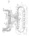
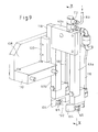
Das in der Zeichnung dargestellte Ausführungsbeispiel umfasst
einen Bereich A, welcher die eigentliche Druckmaschine 10 aufweist,
und einen Bereich B, welcher die Einrichtungen für den
Transport der zu bedruckenden Objekte zur Druckmaschine und für
den Abtransport der bedruckten Objekte von der Druckmaschine zu
nachgeordneten Einrichtungen, also das Handling-System aufweist
(Fig. 1).The embodiment shown in the drawing comprises
an area A, which has the
Die Druckmaschine 10 dient zum Bedrucken von flachen Objekten,
beispielsweise CDs, Kreditkarten oder dgl. Sie weist mehrere
als Wagen ausgebildete Objektträger 14 auf, von denen jeder oberseitig
mit einer Aufnahme 16 für ein Objekt 15 versehen ist.
Die Objektträger 14 werden in Richtung des Pfeiles 17 entlang
einer endlosen Transportbahn 18 bewegt, die aus zwei in einem
horizontalen Abstand voneinander befindlichen linearen Abschnitten
20, 21 sowie zwei etwa halbkreisförmigen Abschnitten
23, 24 besteht, die die beiden linearen Abschnitte 20, 21 miteinander
verbinden. Jedem der beiden linearen Abschnitte 20, 21
der Transportbahn 18 ist eine in der Zeichnung nicht dargestellte
Transportschnecke zugeordnet, die den Transport der Objektträger
14 in den linearen Abschnitten 20, 21 bewirkt. Jedem
der beiden halbkreisförmigen Abschnitte 23, 24 ist jeweils ein
in horizontaler Ebene umlaufendes, in der Zeichnung nur angedeutetes
Antriebsrad 25 zugeordnet, das kontinuierlich oder
diskontinuierlich umlaufen kann. Eine mögliche Ausgestaltung
einer derartigen Maschine ist in US-PS 6,082,256 beschrieben
und dargestellt. Der Offenbarungsgehalt dieser PS wird in den
Offenbarungsgehalt dieser Anmeldung einbezogen.The
Für den Transport der zu bedruckenden Objekte 15 zu den Objektträgern
14 der Druckmaschine und für den Abtransport der bedruckten
Objekte von der Druckmaschine 10 sind im Bereich B
zwei kurvengängige Transportbänder 29, 30 vorgesehen. Beim
Transport auf diesen Bändern sind die Objekte in Form von Stapeln
in Magazinen 32 angeordnet, die in üblicher Weise mit einem
vertikalen Halte- und Führungsdorn 34 versehen sind, der
das jeweils zentrale Loch aller den jeweiligen Stapel bildenden
CDs durchragt. Jedes Magazin weist unterseitig einen tellerartigen
Fuss 33 mit einem oberseitigen Rand 40 auf. Derartige Magazine
sind allgemein üblich und bezüglich ihrer konkreten Ausgestaltung
dem Fachmann bekannt.For the transport of the objects to be printed 15 to the
Da die Objekte 15 einzeln in die Aufnahmen 16 der Objektträger
14 eingelegt werden, ist im Bereich jedes der beiden über den
grössten Teil ihrer Erstreckung parallelen Transportbänder 29,
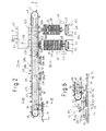
30 eine Vereinzelungsstation 36, 37 (Fig. 2 und 5) vorgesehen,
in denen jeweils ein Magazin positioniert werden kann, welches
mit einem Stapel von zu bedruckenden CDs versehen ist. In jeder
der beiden unmittelbar nebeneinander angeordneten Vereinzelungsstationen
36, 37 ist eine zweiteilige Greifereinrichtung
vorgesehen, deren gemeinsam auf- und abbewegbare Greiferteile
39a, b an Form und Abmessungen des Magazinfusses 33 angepasst
sind und in ihrer Schliessposition den vorstehenden, oberseitigen
Rand 40 des Fusses 33 untergreifen, nachdem das Magazin
durch einen nicht dargestellten bewegbaren Anschlag, der dicht
oberhalb des jeweiligen Transportbandes 29, 30 vorgesehen ist,
angehalten worden ist. Die Greifereinrichtung wird, nachdem sie
geschlossen worden ist und den Fuss 33 erfasst hat, angehoben,
so dass das Magazin sich nicht mehr in Kontakt mit dem im allgemeinen
kontinuierlich umlaufenden jeweiligen Transportband
29 bzw. 30 befindet und der im Magazin befindliche CD-Stapel zu
einer oberhalb des Magazins in einem entsprechenden Abstand vom
jeweiligen Transportband 29 bzw. 30 angeordneten Hubteil 42a
bzw. 42b einer Hub- oder Abnahmeeinrichtung 42 ausgerichtet
ist; die nahe dem der Druckmaschine 10 abgekehrten Ende einer
ersten als Transportbalken ausgebildeten Transporteinrichtung
43 vorgesehen ist (Fig. 2). Letztere erstreckt sich zwischen
den beiden Vereinzelungsstationen 36, 37 einerseits und einem
Drehteller 44 andererseits, welcher mit vier Aufnahmen für das
jeweilige Objekt 15 versehen und in kurzer Entfernung von dem
nächstliegenden linearen Abschnitt 20 der Transportbahn 18 positioniert
ist (Fig. 6).Since the
Der Transportbalken ist mit einem Träger 46 versehen, der zur
Lagerung eines in vertikaler Ebene umlaufenden Transportriemens
dient, der als Zahnriemen 47 ausgebildet ist. Dazu ist an jedem
Ende des Transportbalkens 43 eine Antriebs- bzw. Umkehrrolle
48, 49 angebracht, über die der Zahnriemen 47 geführt ist.
Fig. 2 - 4 lassen erkennen, dass der untere Abschnitt 47a des
Zahnriemens 47 eine an der Unterseite des Trägers 46 vorhandene
längsverlaufende nutförmige Ausnehmung 51 verschliesst, welche
an eine Unterdruckquelle angeschlossen ist. Entlang dem Längsverlauf
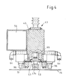
des Trägers 46 ist gemäss der Darstellung der Fig. 4 an
dessen unterer Begrenzungsfläche an dieser anliegend entlang
den Randbereichen des unteren Abschnittes 47a des Zahnriemens
jeweils eine streifenförmige Dichtung 53 angeordnet, welche den
jeweiligen Randbereich untergreift. In Fig. 3 sind diese Dichtungen
53 nicht dargestellt. Die nutförmige Ausnehmung 51 ist
über mehrere Verbindungskanäle 54 mit einer entlang dem Träger
46 des Transportbalkens 43 erstreckenden Unterdruckleitung 56
verbunden, die in Fig. 8 erkennbar ist, die eine zweite als
Transportbalken ausgebildete Transporteinrichtung 90 zeigt.The transport bar is provided with a
FIGS. 2-4 show that the
Am Zahnriemen 47 sind entlang seinem Längsverlauf Saugköpfe angebracht
derart, dass sie sich vom Träger 46 weg und somit im
unteren Abschnitt 47a nach unten und im oberen Abschnitt 47b
nach oben erstrecken. Diese Saugköpfe 58a, 58b sind paarweise
angeordnet derart, dass der Abstand zwischen zwei Saugkopf-Paaren
kleiner ist als der Durchmesser des zu transportierenden
Objektes. Im Zahnriemen 47 sind Löcher 50 angebracht, die mit
dem jeweiligen Saugkopf 58a,b im wesentlichen fluchten und die
Verbindung zwischen der unter Unterdruck stehenden Ausnehmung
51 einerseits und dem jeweiligen Saugkopf andererseits herstellen,
welcher gegenüber dem Zahnriemen 47 vorsteht und an seinem
dem Zahnriemen abgekehrten Ende offen ist. Der Zahnriemen läuft
in Richtung des Pfeiles 61 um, so dass die in den Vereinzelungsstationen
36, 37 jeweils aufgenommenen CDs durch den Abschnitt
47a in noch zu beschreibender Weise zum Drehteller 44
transportiert werden.On the
Die beiden gemeinsam betätigbaren Hubteile 42a, 42b der auf-und
abbewegbar am Transportbalken angebrachten Hubeinrichtung
42 weisen jeweils im wesentlichen die Form eines nach unten offenen
U-Rahmens auf und sind derart angeordnet, dass der Transportbalken
mit dem Zahnriemen 47 sich zwischen den beiden
Schenkeln 63a und 63b des jeweiligen U-Rahmens erstreckt, so
dass der U-Rahmen den Transportbalken mit Zahnriemen 47 übergreift.
Der Abstand zwischen beiden Hubteilen 42a, 42b in
Längsrichtung des Transportbalkens entspricht der Länge eines
Transportschrittes des Zahnriemens 47 sowie dem Abstand zwischen
den beiden Vereinzelungsstationen 36, 37, die entlang dem
Verlauf des Transportbalkens hintereinander angeordnet sind.
Jeder der beiden Schenkel 63a, 63b jedes U-förmigen Rahmens
ist an seinem unteren Ende mit einem Saugkopf-Paar 65a, 65b
versehen, das in geeigneter Weise an die ohnehin vorhandene Unterdruckquelle
anschliessbar ist. Jeder Saugkopf ist - wie
auch alle anderen Saugköpfe - als kurzer Faltenbalg-Abschnitt
ausgebildet.The two jointly actuated lifting
Die in den Vereinzelungsstationen 36, 37 befindlichen Magazine
werden wechselweise entleert, indem die im jeweiligen Magazin
befindlichen CDs nacheinander vom Stapel abgenommen werden. Dazu
wird zunächst der CD-Stapel jedes Magazins durch einen üblichen
Hubarm 45 derart angehoben, dass die zu oberst liegende
CD des Stapels sich in einer Höhe unterhalb des jeweiligen Hubteils
der Abnahmeeinrichtung 42 befindet, in welcher die Saugkopf-Paare
65a, 65b dieses Hubteils in der unteren Lage desselben
mit der oberen Fläche dieser CD in Berührung kommen. Der
Hubarm 45 ist dabei mit einer Hülse 95 in Eingriff, welche verschiebbar
auf dem Dorn 34 des Magazins 32 sitzt und den CD-Stapel
trägt. Der Hubarm hat zudem in bekannter Weise die Funktion,
nach dem Abnehmen der jeweils zu oberst befindlichen CD
den Stapel um die Dicke einer CD nach oben zu bewegen, um so
die jeweils folgende CD in die Position zu bringen, in welcher
sie von den Saugkopf-Paaren 65a, 65b des Hubteils aufgenommen
werden kann.The magazines located in the separating
Im einzelnen läuft das Abnehmen der CDs vom jeweiligen Stapel
so ab, dass zum Entleeren des z. B. in der Vereinzelungsstation
36 befindlichen Magazins der Hauptrahmen 41 der Abnahmeeinrichtung
42 unter Mitnahme des unmittelbar daran angebrachten
U-Rahmens des dieser Station zugeordneten Hubteils 42b in seine
untere Endlage verschoben wird, in welcher die zu beiden
Seiten des Transportbalkens 43 jeweils befindlichen Saugkopf-Paare
65a, 65b an der jeweils zu oberst im Stapel liegenden CD
zur Anlage kommen und auf Grund der Saugwirkung bei der anschliessenden
nach oben gerichteten Bewegung der Abnahmeeinrichtung
42 diese CD mitnehmen und so weit anheben, dass sie
ausser Eingriff mit der Spindel 34 des Magazins kommt und zur
Anlage an das vom Zahnriemen 47 getragene Saugkopf-Paar 58a, b
gebracht wird, welches sich zu diesem Zeitpunkt oberhalb des in
der Vereinzelungsstation 36 vorhandenen Magazins befindet. Sobald
der Kontakt zwischen dem Saugkopf-Paar 58a, b und der CD
hergestellt ist und die CD auch von diesem Saugkopf-Paar getragen
wird, wird der Unterdruck an den beiden Saugkopf-Paaren
65a, 65b des Hubteils 42b abgeschaltet oder reduziert, so dass
nunmehr der Zahnriemen um einen Transportschritt in Richtung
auf den Drehteller 43 unter Mitnahme der am Zahnriemen hängenden
CD vorbewegt wird, wobei die Grösse des Transportschrittes
so gewählt ist, dass die CD bereits im Verlauf dieses Transportschrittes
ausserhalb des Bewegungsbereiches der Hubeinrichtung
42b gelangt und diese somit zur Aufnahme der nächsten CD
wieder nach unten bewegt werden kann, bevor dieser Transportschritt
beendet ist. Die Übergabe der CD von dem jeweiligen
Hubteil 42a, b an den Zahnriemen wird dadurch erleichtert, dass
die durch das jeweilige Hubteil bewirkte Aufwärtsbewegung der
CD durch das in der jeweiligen Vereinzelungsstation befindliche
Saugkopf-Paar 65a, b begrenzt wird. Zwar werden die die Saugköpfe
bildenden Faltenbalgabschnitte unter der Einwirkung der
sich nach oben bewegenden CD etwas zusammengedrückt. Dies ändert
jedoch nichts an der Tatsache, dass die beiden Faltenbalgabschnitte
einen Anschlag darstellen, welcher die Bewegung der
CD nach oben begrenzt, so dass bei entsprechend bemessenem Hub
der Hubeinrichtung die Saugköpfe 65a, b des jeweiligen Hubteils
zwangsläufig von der CD gelöst werden, sobald der auf diese
Saugköpfe einwirkende Unterdruck eine merkliche Reduzierung erfährt.
Der durch die Saugköpfe 65a, b gebildete Anschlag stellt
somit ein zusätzliches Mittel dar, um das Objekt von den Saugköpfen
58a, b des Hubteiles zu lösen.In detail, the removal of the CDs from the respective stack is running
so from that to empty the z. B. in the
Fig. 5 zeigt im Schema die Anordnung der Saugköpfe an der CD in
Draufsicht im Augenblick der Übergabe derselben von den Saugkopf-Paaren
65a, b der Hubeinrichtung 42b der Vereinzelungsstation
36 an die Saugkopf-Paare 58a, b des Zahnriemens 47.Fig. 5 shows in the scheme the arrangement of the suction cups on the CD in
Top view at the moment of transferring the same from the suction head pairs
65a, b of the
Das Vorhandensein von zwei Entleerungsstationen hat lediglich
den Zweck, auch während des Zeitraums, in welchem ein leeres
Magazin gegen ein volles Magazin mit zu bedruckenden Objekten
ausgewechselt wird, eine kontinuierliche Beschickung des Zahnriemens
47 und damit der nachgeordneten Druckmaschine 10 mit
CDs zu gewährleisten. Da jedoch die Entleerungsstation 37 in
Transportrichtung 61 der vom Zahnriemen 47 getragenen CDs sich
hinter der Entleerungsstation 36 befindet, müssen Vorkehrungen
getroffen werden um sicherzustellen, dass die dem jeweils in
der Entleerungsstation 36 befindlichen Magazin entnommenen CDs,
die beim Transport in Richtung 61 auf den Drehteller 44 die andere
Entleerungsstation 37 passieren müssen, in letzterer keine
Behinderung erfahren. Zu diesem Zweck ist das der Station 37
zugeordnete Hubteil 42a unter Zwischenschaltung einer pneumatisch
betriebenen Zylinder-Kolben-Einheit 57 mit dem Hauptrahmen
41 der Abnahmeeinrichtung 42 verbunden derart, dass die
vertikal hin- und herbewegbare Kolbenstange 59 der Einheit 57
mit dem U-Rahmen des Hubteils 42a verbunden ist.The presence of two emptying stations only has
the purpose, even during the period in which a vacant
Magazine against a full magazine with objects to be printed
is replaced, a continuous supply of the
In Fig. 2 der Zeichnung ist der Kolben der Einheit 57 so beaufschlagt,
dass die Kolbenstange sich in ihre obere Endlage bewegt
und dabei das Hubteil 42a mitgenommen hat, welches jetzt
relativ zum Hauptrahmen 41 so hoch positioniert ist, dass sich
die unteren Begrenzungen der Saugköpfe 65a, 65b des Hubteils
42a immer oberhalb des Niveaus befinden, in welchem die vom unteren
Abschnitt 47a des Zahnriemens getragenen CDs angeordnet
sind. Während der Entleerung des jeweils in der Station 36 befindlichen
Magazins läuft somit das der anderen Entleerungsstation
37 zugeordnete und unwirksam gestellte Hubteil 42a leer
mit. Entsprechendes gilt auch für das Hubteil 42b bei Entleerung
des in der Station 37 jeweils befindlichen Magazins, wenngleich
hier nicht die Notwendigkeit besteht, das Hubteil 42b
höher zu positionieren, da bei dieser Konstellation die Entleerungsstation
36 nicht von am Zahnriemen 47 hängenden Objekten
passiert wird.In Fig. 2 of the drawing, the piston of the
Mit der unmittelbar nach Entleerung des in der Station 36 befindlichen
Magazins erfolgenden Umstellung auf das jeweils in
der Station 37 befindliche Magazin wird durch entsprechende Betätigung
der Kolben-Zylinder-Einheit 57 das Hubteil 42a nach
unten in seine wirksame Position verschoben, in welcher die von
ihm getragenen Saugkopf-Paare 65a, b die Höhenlage einnehmen,
welche der Höhenlage der Saugkopf-Paare des anderen Hubteiles
42b entspricht. Die Änderung der Position des Hubteiles 42a relativ
zum Hauptrahmen 41 kann erfolgen, sobald die letzte dem
in der Station 36 befindlichen Magazin entnommene, am unteren
Abschnitt 47a des Zahnriemens hängende CD den in der Station 37
befindlichen Stapel passiert hat. Da bei dem in der Zeichnung
dargestellten Ausführungsbeispiel die beiden Entleerungsstationen
36, 37 um einen Transportschritt des Zahnriemens 47 voneinander
entfernt sind, kann die erste dem Stapel in der Station
37 entnommene CD unmittelbar auf die letzte CD folgen, welche
dem Magazin in der Station 36 entnommen worden war, so dass
sämtliche Saugkopf-Paare 58a, b des Zahnriemens 47 trotz des
Wechsels der Entleerungsstationen mit CDs bestückt sind. Dies
ergibt sich auch daraus, dass der Transportweg von der Station
37 zur Abwurfstation oberhalb des Drehtellers 44 um einen
Transportschritt kürzer ist als von der anderen Entleerungsstation
36.With the immediately after emptying of the located in the
Während des Entleerens des in der Station 37 befindlichen Magazins
ist das in der Station 36 befindlichen Magazin bzw. dessen
Stapel nur so weit angehoben, dass die zuoberst liegende CD
dieses Stapels nicht mit den Saugköpfen des der Station 36 zugeordneten
Hubteils 42b in Berührung kommt, das, wie bereits
erwähnt, leer mitläuft.While emptying the located in the
Bei einem Wechsel von einem in der Station 37 befindlichen Magazin
zu dem folgenden in der Station 36 befindlichen Magazin,
das bereits durch die Greiferteile angehoben ist, wird dessen
Stapel durch den zugehörigen Hubarm 45 angehoben, damit die zuoberst
liegende CD jetzt mit dem Saugkopf des Hubteils 42b in
Berührung kommt, wenn letzteres seine untere Position einnimmt.
Dabei ergibt sich die Besonderheit, dass die letzte dem in der
Station 37 befindlichen Magazin zu entnehmende CD und die erste
dem in der Station 36 befindlichen Magazin zu entnehmende CD
gleichzeitig vom jeweiligen Hubteil 42a bzw. 42b aufgenommen
und zur Anlage an das in der jeweiligen Station befindliche
Saugkopf-Paar 58a, b des Riemens 47 gebracht werden. Unmittelbar
danach wird in der vorstehend beschriebenen Weise das Hubteil
42a nach oben in seine unwirksame Lage verschoben.When changing from a located in the
Bei dem in der Zeichnung dargestellten Ausführungsbeispiel gelangt
die in der jeweiligen Vereinzelungsstation vom Zahnriemen
47 übernommene CD nach vier bzw. fünf Transportschritten des
Zahnriemens - in Abhängigkeit davon, in welcher Vereinzelungsstation
37 oder 36 die CD aufgenommen wird - in die Abwurfstation
71, in welcher sich die jeweilige CD oberhalb einer von
vier Aufnahmen 70 befindet, die am schrittweise rotierbaren
Drehteller 44 vorhanden sind. Der Abwurf der CD vom jeweiligen
Saugkopf-Paar 58a, b des Zahnriemens 47 erfolgt durch Aufheben
oder Reduzieren des in den Saugköpfen wirksamen Unterdruckes in
der Abwurfstation.In the embodiment shown in the drawing passes
in the respective separating station from the
Dazu ist der Transportbalken 43 im Bereich der Abwurfstation 71
mit Zuleitungen 64 für Druckluft versehen, die auf die jeweils
in der Abwurfstation befindlichen Saugköpfe 58a, 58b einwirkt,
somit den Unterdruck darin aufhebt und die an diesen hängende
CD beaufschlagt. Bei dem in der Zeichnung dargestellten Ausführungsbeispiel
ist innerhalb der längsverlaufenden Ausnehmung 51
oberhalb der zwischen zwei Transportschritten in der Abwurfstation
71 befindlichen Saugköpfe 58a, b jeweils ein vertikal verlaufender
mit der Zuleitung 64 verbundener Stutzen 66 angeordnet,
dessen Austrittsöffnung sich genau oberhalb des Loches 50
im Zahnriemen 47 befindet, das die Verbindung zwischen der Ausnehmung
51 und dem daran anschliessenden Saugkopf 58a bzw. 58b
herstellt.For this purpose, the
Mit Erreichen der Abwurfstation 71 wird auf beide Saugköpfe
58a, b ein Druckluftstoss zur Einwirkung gebracht, der nicht
nur den Unterdruck für kurze Zeit aufhebt, sondern eine zusätzliche
Kraft wirksam werden lässt, durch welche die CD von den
beiden sie tragenden Saugköpfen gelöst wird. Die CD fällt dabei
in die jeweils darunter befindliche Aufnahme 70 des Drehtellers
44. Sie wird dann durch drei Transportschritte von jeweils 90°
des Drehtellers 44 in Richtung des Pfeils 61 über zwei Zwischenpositionen
in eine Transferstation 73 (Fig. 1) gebracht,
in welcher sich die die CD aufweisende Aufnahme und damit die
CD in kurzem Abstand von der Eingabestation 72 der Transportbahn
18 der Druckmaschine 10 befinden. In den beiden Zwischenpositionen
auf dem Wege von der Abwurfstation 71 zur Transferstation
73 kann die CD z. B. bezüglich ihrer Identität und/oder
anderer Kriterien geprüft werden.Upon reaching the
In der jeweiligen Aufnahme 70 des Drehtellers 44 erfährt die
vom Transportbalken 43 abgeworfene CD eine erste Ausrichtung.
Dazu ist jede der Aufnahmen des Drehtellers mit einem zum Mittelpunkt
der Aufnahme 70 koaxial umlaufenden Rand 69 versehen,
der innenseitig derart konisch abgeschrägt ist, dass der Durchmesser
des Randes, der sich über mehr als 180° des Umfanges der
Aufnahme erstreckt, unten einen geringeren Durchmesser aufweist
als an seiner oberen Begrenzung, so dass die vom Transportbalken
43 fallende CD im Verlauf ihrer Bewegung innerhalb des Randes
69 bis zur Auflage auf der oberen Begrenzungsfläche der jeweiligen
Aufnahme 70 zentriert und somit in eine definierte Lage
gebracht wird.In the
Der Abstand zwischen der Transferstation 73 des Drehtellers 44
und der Eingabestation 72 der Druckmaschine 10 wird durch eine
Transfereinrichtung 75 überbrückt, die zwei in horizontaler Ebene
um 180° hin- und herbewegbare um 180° gegeneinander versetzte
Arme 76, 78 aufweist, die von einer gemeinsamen vertikalen
Welle 80 getragen sind. Diese Welle ist mit den beiden Armen
76, 78 um eine kurze Wegstrecke von z. B. 15 - 20 mm auf-und
abbewegbar angebracht. Nahe dem Ende jedes der beiden Arme
76, 78 sind unterseitig zwei jeweils einen Saugkopf 81a, 81b
bildende Faltenbalgabschnitte an diesen befestigt, die unterseitig
mit einer Öffnung versehen und an eine Unterdruckquelle
anschliessbar sind. In jeder der beiden Endpositionen der
Transfereinrichtung 75 befindet sich einer der Arme 76, 78 oberhalb
des Drehtellers 44 in der Übergabestation 71 und der
andere Arm sich oberhalb der Aufnahme 16 des Objektträgers 14,
der jeweils in der Eingabestation 72 der Druckmaschine 10 positioniert
ist. Zwischen beiden Saugköpfen 81a, b jedes Armes 76,
78 ist ein vertikaler Zentrierdorn 84 am Arm angebracht, der
sich zu seinem freien Ende hin konisch verjüngt und an seinem
dem jeweiligen Arm 76, 78 zugekehrten Endbereich einen Durchmesser
aufweist, welcher derart an den Durchmesser einer in der
CD vorhandenen zentralen Öffnung angepasst ist, dass bei in die
Öffnung der CD eingeführtem Endbereich des Dornes dessen Mantelfläche
mit einer Passung am Rand der Öffnung anliegt, welche
ein Bewegen der CD quer zur Längsachse des Dornes ausschliesst.The distance between the
Bei in der unteren Position befindlicher Transfereinrichtung 75
sind die beiden Saugköpfe 81a, b des in der Transferstation 73
befindlichen Arms 76 gegen die Oberseite der CD gepresst, die
in der jeweils in der Transferstation 73 positionierten Aufnahme
70 des Drehtellers 44 liegt. Dabei sind die die Saugköpfe
bildenden Faltenbalgabschnitte - wie auch in allen anderen Fällen
- etwas zusammengedrückt. Der Zentrierdorn ist im Verlauf
der vorangegangenen Absenkbewegung der Transfereinrichtung 75
in die zentrale Öffnung der CD eingeführt worden derart, dass
durch die vorbeschriebene Konizität und die enge Passung eine
endgültige genaue Ausrichtung der CD erfolgt, so dass diese eine
definierte Lage einnimmt. Bei der darauffolgenden kurzen
Aufwärtsbewegung der Transfereinrichtung 75 wird die CD durch
den zumindest jetzt auf die Saugköpfe einwirkenden Unterdruck
aus der Aufnahme 70 heraus gehoben und im Verlauf der folgenden
Drehbewegung um 180° über die Aufnahme 16 des zu diesem Zeitpunkt
in der Eingabestation 72 befindlichen Objektträgers 14
gebracht. Bei der folgenden Absenkbewegung der Transfereinrichtung
75 wird die CD in der Aufnahme des in der Station 72 befindlichen
Objektträgers 14 abgelegt, welcher zu diesem Zeitpunkt
ebenfalls eine definierte Position einnimmt. Der Objektträger
14 ist oberseitig mit einer Öffnung für die Aufnahme des
Zentrierdornes beim Absenken der Transfereinrichtung versehen,
so dass die CD auch beim Ablegen in der Aufnahme 16 ihre definierte
Lage nicht verändern kann. Die Aufnahme 16 des Objektträgers
14 ist ebenfalls mit einer Unterdruckquelle verbunden,
so dass im Augenblick der Ablegens der CD in dieser Aufnahme
eine Saugwirkung auf die Unterseite der CD erfolgt und nach Abschalten
des auf die beiden Saugköpfe 81a, b einwirkenden Unterdrucks
die Transfereinrichtung 75 wieder angehoben werden
kann, um den Zentrierdorn ausser Eingriff mit der CD zu bringen,
die während des folgenden Transports der CD durch die Behandlungsstationen
und der darin durchgeführten Behandlungen
durch den in der jeweiligen Aufnahme wirksamen Unterdruck in
ihrer Position gehalten wird.With the
Unmittelbar im Anschluss an die Aufwärtsbewegung der Transfereinrichtung
75, durch die die in der Aufnahme 16 des Objektträgers
14 abgelegte CD freigegeben worden war, wird die Transfereinrichtung
75 wiederum um 180° zurück gedreht, wobei der jeweils
andere Arm 76 bzw. 78 die folgende CD aus der Transferstation
73 in die Aufnahme 16 des nächsten mittlerweile in die
Eingabestation 72 gelangten Objektträgers 14 umsetzt. Um die
Präzision, mit welcher die CD jeweils in der Aufnahme 16 positioniert
wird, ohne grossen technischen Aufwand zu gewährleisten,
kann es zweckmässig sein, die hin- und hergehenden Rotationsbewegungen
der Transfereinrichtung durch einen Anschlag zu
begrenzen, welcher die Endposition der Arme 76 bzw. 78 in der
Eingabestation 72 relativ zur Aufnahme 16 des Objektträgers 14
eindeutig bestimmt.Immediately following the upward movement of the
Nach dem Durchlaufen der Behandlungsstationen der Druckmaschine
10, zu denen auch eine Station 86 gehören kann, in welcher das
auf die jeweilige CD aufgebrachte Druckbild hinsichtlich seiner
Qualität überprüft wird, gelangen die in den Objektträgern liegenden
CDs nacheinander in eine Entnahmestation 88, in welcher
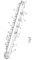
sie aus der Druckmaschine 10 entfernt werden. Dazu ist eine
zweite Transporteinrichtung in Form eines Transportbalkens 90
vorgesehen, dessen grundsätzlicher Aufbau dem des ersten Transportbalkens
43 entspricht, so dass übereinstimmende Teile auch
mit denselben Bezugszeichen versehen sind. Insbesondere Fig. 1
der Zeichnung lässt erkennen, dass sich dieser zweite Transportbalken
90 ohne Zwischenschaltung weiterer Einrichtungen
zwischen der Entnahmestation 88 in der Transportbahn 18 der
Druckmaschine 10 und den beiden Transportbändern 29, 30 für die
Magazine erstreckt.After passing through the treatment stations of the
Der zweite Transportbalken 90 ist ebenfalls mit einem Längsträger
46 und einem Zahnriemen 47 versehen, an welchem in gleicher
Weise Saugköpfe 58a, 58b angebracht sind. Die Antriebsverhältnisse
sind insofern umgekehrt, als bei dem Transportbalken 90
die gezahnte Umlenkrolle 48 angetrieben ist, da der untere Abschnitt
47a des Zahnriemens in Richtung des Pfeiles 91 läuft.The
Nahe dem der Druckmaschine 10 zugekehrten Ende des Transportbalkens
90 ist eine Hubeinrichtung 42 angeordnet, die abweichend
von der mit dem ersten Transportbalken 43 zusammen wirkenden
entsprechenden Einrichtung 42 nur ein Hubteil 42a aufweist.
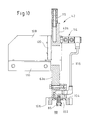
Dieses ist, wie insbesondere Fig. 9 erkennen lässt, ebenfalls
als U-förmiger Rahmen ausgebildet und in der im Zusammenhang
mit dem Transportbalken 43 beschriebenen Weise angeordnet,
trägt jedoch an den beiden Schenkeln 63a, b jeweils nur
einen Saugkopf 65. Jeder der beiden Saugköpfe ist innerhalb eines
Ausschnittes 102 an einem Anschlagteil 104 angeordnet, wie
dies in den Fig. 9 und 10 dargestellt ist. Die beiden Anschlagteile
104 sind jeweils am unteren Ende des Schenkels 63a bzw.
63b angebracht derart, dass der jeweilige Ausschnitt 102 nach
unten offen ist und der zugehörige Saugkopf 65 in unbeanspruchtem
Zustand, also ohne Objekt, gegenüber der unteren Begrenzzung
106 des jeweiligen Anschlagteils 104 etwas nach unten vorsteht,
wie dies insbesondere Fig. 10 zeigt.Near the
Die Hubeinrichtung 42 ist oberhalb der Aufnahme 16 des jeweils
in der Entnahmestation 88 befindlichen Objektträgers 14 mittels
einer Seitenplatte 108 und einer Konsole 110 am Transportbalken
90 befestigt. Sobald der jeweilige Objektträger in dieser Station
angelangt ist, wird das Hubteil 42a nach unten gefahren,
bis die beiden Saugköpfe 65 an der in der Aufnahme liegenden CD
zur Anlage kommen. Dabei werden die beiden Saugköpfe 65 etwas
zusammengedrückt mit der Folge, dass das Objekt mit seiner oberen
Begrenzungsfläche an der unteren Begrenzungsfläche 106 jedes
der beiden Anschlagteile 104 zur Anlage kommt und somit eine
definierte Lage einnimmt, die auch während der folgenden
Aufwärtsbewegung des Hubteils 42a beibehalten wird, da der Umgebungsluftdruck
das Objekt gegen die beiden Anschlagteile 104
drückt. Vor Beginn der Aufwärtsbewegung war der auf die CD in
der Aufnahme 16 des Objektträgers 14 einwirkende Unterdruck abgeschaltet
worden. Im Zuge der Aufwärtsbewegung wird auch hier
das Objekt zur Anlage an dem Saugkopf-Paar 58a, 58b am Untertrum
47a des Zahnriemens 47 gebracht, welches sich jeweils
im Bereich der Hubeinrichtung 42 befindet und auch hier als die
Hubbewegung der CD begrenzender Anschlag wirken kann. In der
bereits im Zusammenhang mit dem Vereinzeln der zu bedruckenden
Objekte beschriebener Weise wird dann die bedruckte CD ausschliesslich
vom Saugkopf-Paar 58a, 58b getragen, nachdem der
in dem Saugkopf-Paar 65 der Hubeinrichtung 42a wirkende Unterdruck
abgeschaltet worden war. Somit wird auch hier analog dem
Vereinzeln der zu bedruckenden Objekte der Vorteil erreicht,
dass die Bewegung des Anhebens der CD - hier aus der Aufnahme
des Objektträgers - einerseits und der Transport dieser CD in
im wesentlichen horizontaler Ebene - hier in Richtung auf die
noch zu beschreibende Sammelstation - andererseits getrennt erfolgen,
wodurch eine erhebliche Steigerung der Durchsatzleistung
der Gesamtmaschine erreicht werden kann.The lifting
Um den Unterdruck innerhalb des Faltenbalges jedes der beiden
Saugköpfe 65 wirksam werden zu lassen, ist das Hubteil 42a mit
einem Anschluss 112 für eine Schlauchleitung 114 versehen, welche
die Verbindung zu einer Unterdruckquelle herstellt und so
flexibel ist, dass sie den Hubbewegungen des Hubteils 42a folgen
kann. Vom Anschluss 112 erfolgt eine Verteilung des Unterdrucks
auf die Saugköpfe 65 der beiden Schenkel 63a und 63b.
Dazu ist ein Verteilerstück 114 vorgesehen, von dem jeweils eine
Leitung 116 zum jeweiligen Saugkopf 65 abgeht. Das Verteilerstück
114 ist ferner mit einem Abzweig 116 versehen, welcher
über ein Ventil mit der Aussenatmosphäre verbindbar ist, um so
beispielsweise bei Übergabe der von den Saugköpfen 65 des Hubteils
42a getragenen CD an die Saugköpfe 58a, b des Zahnriemens
47 den Unterdruck in den Saugköpfen 65 möglichst schnell abbauen
zu können. Das (nicht dargestellte) Ventil des Abzweigs 116
wird somit geöffnet, sobald die CD im Verlauf der Aufwärtsbewegung
des Hubteiles 42a am jeweiligen Saugkopf-Paar 58a, b des
Zahnriemens 47 zur Anlage gekommen ist, ggf. auch Bruchteile
von Sekunden früher, um den Abbau des Unterdruckes in dem Leitungssystem,
an dessen jeweiligem Ende ein Saugkopf 65 angeordnet
ist, zu beschleunigen. Spätestens zu Beginn des folgenden
Abwärtshubes des Hubteiles 42a wird dann die Verbindung zur umgebenden
Atmosphäre durch Schliessen des Ventils geschlossen.To the negative pressure within the bellows of each of the two
Suction heads 65 to be effective, the lifting
Die Hubteile 42a, b der von erstem Transportbalken 43 getragenen
Hubeinrichtung 42 können in entsprechender Weise ausgebildet
sein, wobei um das Volumen der Systeme, die jeweils unter
Unterdruck bzw. Normaldruck oder sogar Überdruck gesetzt werden
müssen, möglichst klein zu halten, jedem der beiden Hubteile
42a und 42b ein eigenes Belüftungsventil zugeordnet ist.The lifting
Weiterhin können die vorstehend im Zusammenhang mit den Fig. 9
und 10 beschriebenen Mittel auch an der Transfereinrichtung 75
vorgesehen sein, um die Druckverhältnisse in deren Saugköpfen
81a, b entsprechend zu steuern.Furthermore, the above in connection with FIGS. 9
and 10 also described on the
Auch beim zweiten Transportbalken 90 wird der Zahnriemen 47
schrittweise bewegt, um die in der Entnahmestation 88 vom jeweiligen
Saugkopf-Paar 58a, b aufgenommene CD in Richtung auf
die Sammelstation 92 bzw. 94 zu transportieren. Die Hubeinrichtung
42a kann wieder nach unten zur Entnahme der nächsten CD
aus dem mittlerweile in der Entnahmestation 88 befindlichen
folgenden Objektträger bewegt werden, sobald die letzte CD den
Bewegungsbereich der Hubeineinrichtung in Richtung des Pfeiles
91 verlassen hat. Die Verwendung lediglich eines Saugkopfes an
jedem Flansch 63a, b des U-Rahmens der Hubeinrichtung 42a - im
Vergleich zu zwei Saugköpfen bei den Hubteilen 42a, b des ersten,
zuführenden Transportbalkens 43 - ist deshalb möglich,
weil die CDs einzeln in den Aufnahmen der Transportwagen liegen
und somit das Entnehmen aus der Aufnahme wesentlich leichter
vonstatten geht als das Anheben einer einzelnen CD von einem
Stapel, wie das in den beiden Vereinzelungsstationen 36, 37 der
Fall ist. Da die bedruckten CD ausnahmslos nur in der einen
Entnahmestation 88 nacheinander aus dem dort jeweils befindlichen
Objektträger 14 herausgenommen werden, braucht für die
Entnahme auch nur eine Hubeinrichtung 42 vorgesehen zu sein.Also in the
Dem anderen Endbereich des Transportbalkens 90 sind die beiden
Sammelstationen 92, 94 für die bedruckten CDs zugeordnet, die
ebenfalls wechselweise benutzt werden, um auch beim Austauch
eines vollen Magazins gegen ein leeres Magazin kontinuierlich
weiter arbeiten zu können. Analog der Anordnung der Vereinzelungsstationen
36, 37 ist die Sammelstation 92 dem Transportband
29, die Sammelstation 94 dem Transportband 30 zugeordnet
derart, so dass beide Stationen 92, 94 entlang dem Längsverlauf
des Transportbalkens 90 positioniert sind.The other end portion of the
In Abhängigkeit davon, welche der beiden Sammelstationen 92, 94
jeweils benutzt wird, werden die an den Saugkopf-Paaren 58a, b
hängenden CDs schrittweise entweder bis zur Entnahmestation 92
oder zur Entnahmestation 94 transportiert. Bei dem in der
Zeichnung dargestellten Ausführungsbeispiel ist die Sammelstation
94 mit einem fast vollständig gefüllten Magazin 32 versehen,
während sich in der Sammelstation 92 ein leeres Magazin
befindet. Beide Magazine sind analog der bereits im Zusammenhang
mit den Vereinzelungsstationen 36, 37 beschriebenen Weise
jeweils durch die beiden Teile 39a, 39b eines Greifers am Fuss
33 erfasst und so weit angehoben, dass das obere Ende der jeweiligen
Spindel 34 sich in einem kurzen Abstand unterhalb der
CD befindet, welche sich jeweils am Zahnriemen 47 hängend in
der jeweiligen Sammelstation, im konkreten Fall der Sammelstation
94, befindet. Die oberhalb des in der jeweiligen Station
92 bzw. 94 befindlichen Magazins vom Zahnriemen 47 gehaltene CD
ist mit ihrer Öffnung zur Spindel 34 des jeweiligen Magazins
ausgerichtet, so dass die CD, wenn sie von dem sie tragenden
Saugkopf-Paar 58a, 58b freigegeben wird und nach unten fällt,
mit der Spindel 34 in Eingriff kommt und entlang derselben nach
unten gleitet, bis sie entweder auf der jeweils zu oberst befindlichen
CD des Stapels oder, bei der ersten CD in der Station
92, nach unten bis auf die Hülse 95 fällt, welche den sich
bildenden Stapel trägt.Depending on which of the two
Sobald das in der Station 94 befindliche Magazin 32 mit CDs gefüllt
ist, wird das Magazin durch entsprechende Abwärtsbewegung
der Teile 39a, 39b des Greifers abgesenkt, bis der Fuss 33 auf
dem Transportband 30 aufsitzt. Danach wird ein dicht oberhalb
des Transportbandes 30 befindlicher Anschlag, an welchem der
Fuss 33 des Magazins 32 seitlich anliegt, entfernt, so dass das
mit bedruckten CDs gefüllte Magazin durch das Förderband 30 abtransportiert
werden kann.Once the located in the
Fig. 7 zeigt die Situation kurz vor dem Wechsel von der Sammelstation
94 zur Sammelstation 92. In letzterer befindet sich das
noch leere Magazin 32 bereits in der Position, in welcher es
die bedruckten CDs aufnehmen wird. Es ist ohne weiteres möglich,
dass beide Magazine gleichzeitig die obere Endposition
einnehmen, da sich das obere Ende der jeweiligen Spindel 34 in
dieser Position zwar nur in einem geringen Abstand unterhalb
der Bewegungsbahn der an den Saugköpfen 58a, 58b hängenden CDs
befindet, jedoch die Bewegung der CDs nicht behindert.Fig. 7 shows the situation shortly before the change from the collecting
Bei jedem Magazinwechsel ist so ein nahtloser Übergang zwischen
den in den beiden Sammelstationen jeweils befindlichen Magazinen
möglich, zumal die einzige wesentliche dazu noch erforderliche
Massnahme darin besteht, die Beeinflussung des während
des Transports auf die Saugköpfe 58a, b des Zahnriemens 47 einwirkenden
Unterdrucks zum Zwecke des Abwerfens der CD so zu
steuern, dass jedenfalls nach einem Wechsel von der Sammelstation
94 zur Sammelstation 92 die zum Abwerfen der CD erforderliche
Druckerhöhung innerhalb des jeweiligen Saugkopf-Paares
58a, b nur noch in der Sammelstation 92 erfolgt und somit der
für das Halten der CDs am Zahnriemen 47 erforderliche Unterdruck
beim Passieren der Sammelstation 94 aufrechterhalten
bleibt. Es ist natürlich auch möglich, die für die Druckerhöhung
in den Saugkopf-Paaren 58a, b erforderlichen Massnahmen
zum Abwerfen der CDs immer nur in der Station durchzuführen,
die jeweils zum Stapeln der CDs benutzt wird.Each time the magazine is changed, there is a seamless transition between
the magazines in each of the two collecting stations
possible, especially since the only essential to this still required
Measure consists in influencing the during
the transport to the suction heads 58a, b of the
Um eine Gewähr dafür zu haben, dass nach Druckerhöhung in dem
jeweils in der Abwerfstation 71 bzw. einer der Sammelstationen
92, 94 befindlichen Saugkopf-Paar 58a, b die CD auch tatsächlich
von den jeweiligen Saugköpfen frei kommt, sind bei dem in
der Zeichnung dargestellten Ausführungsbeispiel in diesen drei
Stationen zusätzliche Mittel vorgesehen, um die CDs von den
Saugköpfen 58a, b zu lösen. Es handelt sich dabei um zu beiden
Seiten des jeweiligen Transportbalkens 43 bzw. 90 nahe der unteren
Begrenzung desselben derart paarweise angebrachte Abwerfer
96 (Fig. 4 und 8), dass jeweils ein Abwerfer an jeder Seite
des Transportbalkens 43 bzw. 90 vorhanden ist und beide Abwerfer
eines Paares einander gegenüberliegen. Die Abwerfer sind
als kleine, vertikal hin- und herverschiebbare Kolben ausgebildet,
die beispielsweise unter der Einwirkung von Druckluft gegen
die Kraft einer Feder nach unten verschiebbar sind und dabei
mit ihrem unteren Ende gegen die obere Fläche der CD drücken
und diese somit in kontrollierter Weise um eine Wegstrecke
nach unten verschieben, die in jedem Fall ausreicht, um die CD
von dem sie tragenden Saugkopf-Paar 58a, b zu lösen. Diese Abwerfer
96 können in Abhängigkeit von einem Programm oder
sonstwie, beispielsweise in Abhängigkeit von den Transportbewgungen
des jeweiligen Zahnriemens 47 gesteuert werden. Auf
Grund der symmetrischen Anordnung der beiden Abwerfer zur jeweiligen
CD ist eine Gewähr dafür gegeben, dass die CD während
des kurzen Weges, der zurückzulegen ist, bis sie in der jeweils
in der Abwerfstation 71 befindlichen Aufnahme 70 des Drehtellers
44 liegt bzw. mit dem Dorn 34 des jeweiligen Magazins 32
in Eingriff kommt, die dafür erforderliche Ausrichtung zur Aufnahme
bzw. zum Dorn beibehält.To have a guarantee that after pressure increase in the
each in the
Weitere Abwerfer 96 können am Transportbalken 90 zwischen der
Entnahmestation 72 und der in Transportrichtung 91 der CDs ersten
Sammelstation 94 vorgesehen sein, um beispielsweise CDs,
die bei der Kontrolle des Druckbildes in der Station 86 der
Druckmaschine 10 als fehlerhaft sich herausgestellt haben, aus
dem Transportstrom zu entfernen. Dabei werden in Abhängigkeit
vom Ergebnis der Prüfung in der Kontrollstation 86 (Fig. 1)
oder in einer anderen Kontrollstation (z. B. Identität) die in
der entsprechenden Position zwischen zwei Transportschritten
des Zahnriemens 27 jeweils befindlichen Saugkopf-Paare mit
Druckluft beaufschlagt und die zugehörigen Abwerfer 96 betätigt,
wobei darunter ebenfalls Magazine für die Aufnahme dieser
aussortierten CDs vorgesehen sein können. Die Beaufschlagung
mit Druckluft kann z. B. in der im Zusammenhang mit der Abwerfstation
71 beschriebenen Weise unter Verwendung von Druckluftanschlüssen
64 und -stutzen 66 erfolgen.
Die mit den zu bedruckenden CDs gefüllten Magazine 32 werden am
Eingabeende 98 des Förderbandes 29 auf dessen Obertrum gesetzt,
und zwar einschliesslich jener Magazine, die in der Vereinzelungsstation
37 des zweiten Förderbandes 30 entleert werden.
Fig. 1 der Zeichnung lässt erkennen, dass die beiden Transportbänder
29, 30 über einen wesentlichen Teil ihrer Länge parallel
und unmittelbar nebeneinander verlaufen. In Transportrichtung
99 beider Förderbänder 29, 30 sind unmittelbar vor den beiden
Vereinzelungsstationen 36, 37 die zwischen den beiden Förderbändern
29, 30 verlaufenden Führungsschienen mit einer Durchbrechung
97 versehen, deren Länge in Transportrichtung 89 geringfügig
grösser ist als der grösste Durchmesser eines Magazins
32. Diese in den Führungsschienen 98 vorhandene Lücke 97
ermöglicht es, jedes zweite Magazin mit unbedruckten Objekten
vom Band 29 quer auf das Band 30 zu schieben, so dass das Band
30 über das Band 29 mit Magazinen beschickt wird. Dadurch wird
eine Vereinfachung erreicht, da alle Magazine mit zu bedruckenden
Objekten nur an einer Stelle auf dasselbe Band aufgegeben
zu werden brauchen. Die Querbewegung jedes zweiten Magazins vom
Band 29 auf das Band 30 erfolgt automatisch durch einen quer
zur Transportrichtung 89 im Bereich der Lücke hin- und herbewegbaren
Schieber, welcher in Abhängigkeit von einem Programm
oder irgendwelchen Betriebszuständen die Querverschiebung jeweils
eines Magazins auf das Band 30 bewirkt.The filled with the CDs to be printed
Nach Entleeren des jeweils in der Vereinzelungsstation 36 bzw.
37 befindlichen Magazins wird dieses wieder durch entsprechende
Betätigung der Greiferteile 39a, b auf das jeweilige Band 20
bzw. 30 abgesenkt und von diesem in Richtung auf die jeweilige
Sammelstation 92 bzw. 94 mitgenommen, bevor es nach einer Verweilzeit
in dem Stauraum zwischen jeweiliger Vereinzelungsstation
und zugeordneter Sammelstation in die jeweilige Sammelstation
gelangt und dort in der bereits beschriebenen Weise mit
bedruckten Objekten gefüllt wird. Das gefüllte Magazin wird in
Richtung auf das Austragsende 99 des jeweiligen Transportbandes
transportiert, wo es dann aus dem Bereich B herausgenommen
wird.After emptying of each in the separating
Alle Bewegungen der verschiedenen Transporteinrichtungen im Bereich
B werden von einem zentralen Antrieb mechanisch abgeleitet.
So wird das Schrittgetriebe für den Drehteller 44 über einen
Riementrieb vom zentralen E-Motor der Vorrichtung angetrieben.
Von der schrittweise erfolgenden Transportbewegung des
Drehtellers wird die schrittweise Bewegung des Zahnriemens 47
des ersten Transportbalkens 43 abgeleitet. Die schrittweise Bewegung
des Zahnriemens 47 des zweiten Transportbalkens 90 wird
von der Bewegung des Zahnriemens des ersten Transportbalkens
abgeleitet. Das Pendelgetriebe für die Transfereinrichtung 75
wird von der Welle des Schrittgetriebes angetrieben. Auf der
durchgehenden Welle des Pendelgetriebes befinden sich drei Kurven,
welche über jeweils eine Koppelstange die Hubbewegungen
der Hubeinrichtungen 42 an erstem und zweitem Transportbalken
sowie die Hubbewegungen der Transfereinrichtung bewirken.All movements of various transport facilities in the area
B are mechanically derived from a central drive.
Thus, the step gear for the
An den Hubteilen 42a und 42b ist jeweils wenigstens eine Führungsleiste
118 angebracht, welche in wenigstens einem Schuh
120 gleitet, welcher als Führungsmittel an dem feststehenden
Bereich der Hubeinrichtung 42 angebracht ist. Die die Hubbewegungen
übertragende Koppelstange greift jeweils an den Hubteilen
bzw. am die Hubteile 42a und 42b tragenden Hauptrahmen 41
an. At the
- AA
- Bereich mit DruckmaschineArea with printing machine
- BB
- Bereich für die Handhabung der ObjekteArea for handling the objects
- 1010
- Druckmaschinepress
- 1414
- Objektträgerslides
- 1515
- Objektobject
- 1616
- Aufnahmeadmission
- 1717
- Pfeilarrow
- 1818
- Transportbahntransport path
- 2020
- linearer Abschnittlinear section
- 2121
- linearer Abschnittlinear section
- 2323
- halbkreisförmiger Abschnittsemicircular section
- 2424
- halbkreisförmiger Abschnittsemicircular section
- 2525
- Antriebsraddrive wheel
- 2929
- Transportbandconveyor belt
- 3030
- Transportbandconveyor belt
- 3232
- Magazinmagazine
- 3333
- FussFoot
- 3434
- Dornmandrel
- 3636
- Vereinzelungsstationseparating station
- 3737
- Vereinzelungsstation separating station
- 39a,b39a, b
- Greiferteilgripper part
- 4040
- Randedge
- 4141
- Hauptrahmen von 42Main frame of 42
- 4242
- Hub- oder AbnahmeeinrichtungLifting or acceptance device
- 42a,b42a, b
- Hubteillifting part
- 4343
- erster Transportbalkenfirst transport bar
- 4444
- Drehtellerturntable
- 4545
- Hubarmlifting arm
- 4646
- Trägercarrier
- 4747
- Zahnriementoothed belt
- 47a47a
- unterer Abschnitt von 47lower section of 47
- 47b47b
- oberer Abschnitt von 47upper section of 47
- 4848
- Umlenkrolleidler pulley
- 4040
- Umlenkrolleidler pulley
- 5050
- Loch in 47Hole in 47
- 5151
- Ausnehmung in 46Recess in 46
- 5353
- Dichtungpoetry
- 5454
- Verbindungskanalconnecting channel
- 5656
- UnterdruckleitungVacuum line
- 5757
- Zylinder-Kolben-EinheitCylinder-piston unit
- 58a,b58a, b
- Saugkopfsuction head
- 5959
- Kolbenstangepiston rod
- 6060
- Lochhole
- 6161
- Pfeilarrow
- 63a,b63a, b
- Schenkelleg
- 6464
- Zuleitung für DruckluftSupply line for compressed air
- 6565
- Saugkopfsuction head
- 65a,b65a, b
- Saugkopfsuction head
- 6666
- StutzenSupport
- 6969
- Randedge
- 7070
- Aufnahme in 44Recording in 44
- 7171
- AbwerfstationAbwerfstation
- 7272
- Eingabestationinput station
- 7373
- Transferstationtransfer station
- 7474
- Aufnahme in 44Recording in 44
- 7575
- Transfereinrichtung transfer device
- 7676
- Arm von 75Arm of 75
- 7878
- Arm von 75Arm of 75
- 8080
- Wellewave
- 81a,b81a, b
- Saugkopf-PaarSuction head pair
- 8484
- Positionierdornpositioning mandrel
- 8686
- Kontrollstationcontrol station
- 8888
- Entnahmestationremoval station
- 8989
- Pfeilarrow
- 9090
- Transportbalkentransport bar
- 9191
- Pfeilarrow
- 9292
- Sammelstationcollection station
- 9494
- Sammelstationcollection station
- 9595
- Hülseshell
- 9696
- Abwerferejector
- 9797
- Lücke in FührungsschienenGap in guide rails
- 9898
- Eingabeinput
- 9999
- Austragdischarge
- 100100
- Führungsschieneguide rail
- 102102
- Ausschnittneckline
- 104104
- Anschlagteilstop part
- 106106
- untere Begrenzung von 104lower limit of 104
- 108108
- Platteplate
- 110110
- Konsoleconsole
- 112112
- Anschlussconnection
- 114114
- Verteilerstückmanifold
- 116116
- Abzweigjunction
- 118118
- Führungsleisteguide rail
- 120120
- Schuhshoe
Claims (22)
Applications Claiming Priority (2)
| Application Number | Priority Date | Filing Date | Title |
|---|---|---|---|
| DE102004012078A DE102004012078A1 (en) | 2004-03-12 | 2004-03-12 | Device for feeding and removing objects to and from a machine for decorating the same |
| DE102004012078 | 2004-03-12 |
Publications (1)
| Publication Number | Publication Date |
|---|---|
| EP1574335A1 true EP1574335A1 (en) | 2005-09-14 |
Family
ID=34813669
Family Applications (1)
| Application Number | Title | Priority Date | Filing Date |
|---|---|---|---|
| EP04026762A Withdrawn EP1574335A1 (en) | 2004-03-12 | 2004-11-11 | Device for feeding objects to- and removing from adecorating machine |
Country Status (5)
| Country | Link |
|---|---|
| US (1) | US20050199143A1 (en) |
| EP (1) | EP1574335A1 (en) |
| CN (1) | CN1666940A (en) |
| DE (1) | DE102004012078A1 (en) |
| TW (1) | TWI275550B (en) |
Families Citing this family (12)
| Publication number | Priority date | Publication date | Assignee | Title |
|---|---|---|---|---|
| DE102006003056B4 (en) * | 2006-01-20 | 2014-05-08 | Phoenix Contact Gmbh & Co. Kg | Ink printer for printing on objects |
| SG173426A1 (en) * | 2009-02-26 | 2011-09-29 | Ppt Res Inc | Corrosion inhibiting compositions |
| CN104567777B (en) * | 2013-10-18 | 2017-09-26 | 苏州东南碳制品有限公司 | A kind of carbon brush Thickness sensitivity machine |
| DE102014218308B4 (en) | 2014-09-12 | 2021-12-23 | Kba-Kammann Gmbh | Transport device for objects to be processed in a processing machine and / or processed there |
| DE102014218310B4 (en) | 2014-09-12 | 2017-06-01 | Kba-Kammann Gmbh | Transport device for to be processed in a processing machine and processed there objects |
| DE102014218306A1 (en) | 2014-09-12 | 2016-03-17 | Kba-Kammann Gmbh | Device for providing thermoplastic printing ink on a printing form of a printing unit |
| DE102014218314B4 (en) | 2014-09-12 | 2017-06-01 | Kba-Kammann Gmbh | Method for operating a transport device for a plurality of objects to be processed and / or processed in a processing machine |
| DE102014218313B4 (en) | 2014-09-12 | 2017-05-04 | Kba-Kammann Gmbh | Transport device for processing in a processing machine and / or processed there objects |
| CN105774207B (en) * | 2014-12-26 | 2018-12-21 | 深圳富泰宏精密工业有限公司 | Positioning device |
| DE102016220970B4 (en) | 2016-10-25 | 2022-12-08 | Kba-Kammann Gmbh | Printing machine for printing at least one print image on a substrate surface |
| DE102017206936A1 (en) | 2017-04-25 | 2018-10-25 | Kba-Kammann Gmbh | Method for printing on each of a lateral surface and a base surface having bodies and apparatus for transferring at least one such body from a first processing position to a second processing position |
| JP2020033030A (en) * | 2018-08-27 | 2020-03-05 | 昭和アルミニウム缶株式会社 | Can body manufacturing system |
Citations (2)
| Publication number | Priority date | Publication date | Assignee | Title |
|---|---|---|---|---|
| JPH0858062A (en) * | 1994-08-19 | 1996-03-05 | Nippon Bunka Seiko Kk | Dc multicolor printer |
| US6082256A (en) | 1997-10-14 | 2000-07-04 | Werner Kammann Maschinenfabrik Gmbh | Apparatus and method of decorating articles using a transport screw with a varying screw flight pitch |
Family Cites Families (12)
| Publication number | Priority date | Publication date | Assignee | Title |
|---|---|---|---|---|
| GB1075821A (en) * | 1964-01-18 | 1967-07-12 | Lawrence Engineering Company L | Improvements relating to pallet transfer mechanisms |
| IT1053104B (en) * | 1975-12-19 | 1981-08-31 | Azionaria Costruzioni Acma Spa | APPARATUS TO TRANSFER ... ACCORDING TO A PREDETERMINED STEP ... OBJECTS TO A RECEIVING CONVEYOR ... THE OBJECTS COMING FROM IRREGULAR INTERVALS FROM A DISPENSING CONVEYOR |
| DE2927038A1 (en) * | 1979-07-04 | 1981-01-15 | Laeis Werke Ag | Deburring and stacking machine for unbaked ceramic plates, etc. - which are carried automatically through rows of deburring stations located in several parallel rows |
| NL8501898A (en) * | 1984-08-17 | 1986-03-17 | Staufner Helmut | APPARATUS FOR SORTING PRINTED WRITINGS, SUCH AS NEWSPAPERS, MAGAZINES, EPISODES, POCKETS OR THE LIKE. |
| US4862798A (en) * | 1985-11-04 | 1989-09-05 | American Screen Printing Equipment Company | Cylindrical object screen printer with object centering means |
| US5165340A (en) * | 1991-03-06 | 1992-11-24 | Karlyn William M | Multicolor printing system for the silk-screen printing of compact discs |
| US5644895A (en) * | 1995-05-01 | 1997-07-08 | Johnson & Johnson Vision Products, Inc. | Packaging arrangement |
| SG50380A1 (en) * | 1995-12-09 | 1998-07-20 | Advanced Systems Automation Pt | Pick and place system |
| US5730048A (en) * | 1997-01-06 | 1998-03-24 | Averill; Michael J. | System for the printing of small flat objects using direct rotary printing apparatus |
| FR2780961B1 (en) * | 1998-07-10 | 2000-10-13 | Dubuit Mach | LOADING AND UNLOADING DEVICES FOR A PRINTING MACHINE |
| FR2800006B1 (en) * | 1999-10-22 | 2002-01-18 | Dubuit Mach | PRINTING MACHINE WITH OBJECT HOLDER COMPRISING MEANS FOR LIFTING THE OBJECT, AND OBJECT HOLDER FOR PRINTING MACHINE |
| US6991524B1 (en) * | 2000-07-07 | 2006-01-31 | Disc Go Technologies Inc. | Method and apparatus for reconditioning digital discs |
-
2004
- 2004-03-12 DE DE102004012078A patent/DE102004012078A1/en not_active Withdrawn
- 2004-11-11 EP EP04026762A patent/EP1574335A1/en not_active Withdrawn
- 2004-12-02 US US11/002,056 patent/US20050199143A1/en not_active Abandoned
-
2005
- 2005-01-11 CN CN200510003935.6A patent/CN1666940A/en active Pending
- 2005-01-14 TW TW094101066A patent/TWI275550B/en not_active IP Right Cessation
Patent Citations (2)
| Publication number | Priority date | Publication date | Assignee | Title |
|---|---|---|---|---|
| JPH0858062A (en) * | 1994-08-19 | 1996-03-05 | Nippon Bunka Seiko Kk | Dc multicolor printer |
| US6082256A (en) | 1997-10-14 | 2000-07-04 | Werner Kammann Maschinenfabrik Gmbh | Apparatus and method of decorating articles using a transport screw with a varying screw flight pitch |
Non-Patent Citations (1)
| Title |
|---|
| PATENT ABSTRACTS OF JAPAN vol. 1996, no. 07 31 July 1996 (1996-07-31) * |
Also Published As
| Publication number | Publication date |
|---|---|
| TW200530104A (en) | 2005-09-16 |
| CN1666940A (en) | 2005-09-14 |
| DE102004012078A1 (en) | 2005-09-29 |
| TWI275550B (en) | 2007-03-11 |
| US20050199143A1 (en) | 2005-09-15 |
Similar Documents
| Publication | Publication Date | Title |
|---|---|---|
| DE2814686C2 (en) | Conveyor | |
| DE2543692C2 (en) | Device for use in emptying envelopes | |
| DE102006023111A1 (en) | Device for coating objects | |
| EP1574335A1 (en) | Device for feeding objects to- and removing from adecorating machine | |
| DE1431610B1 (en) | Device for feeding and discharging containers to be printed | |
| DE2124748A1 (en) | Device for deburring the neck of hollow plastic bodies | |
| EP2049063B1 (en) | Device and method for ejecting at least one capsule. | |
| DE2058606B2 (en) | Device for the continuous conveying and alignment of individual sheets | |
| DE3009328A1 (en) | MACHINE FOR LOCKING CONTAINERS GUIDED AT HIGH SPEED IN A STRAIGHT LINE | |
| DE2155114C2 (en) | Transport device for guiding a number of identical carriages in a circuit | |
| DE2924827A1 (en) | Filled bags palleting conveyor - has bag aligning guides and laterally movable track with some driven rollers in front of transfer station | |
| DE2756473C2 (en) | ||
| DE19511296C2 (en) | Device for lifting and transporting flat objects | |
| EP0751086B1 (en) | Device for removing air inclusions from paper stacks | |
| DE1561121A1 (en) | Sheet feeder | |
| DE597552C (en) | Machine for sorting documents etc. like | |
| DE3135549C2 (en) | ||
| EP2776347B1 (en) | Feeding device for container closures | |
| DE10355261A1 (en) | Sheet printer has sheet feed brake to slow sheets for discharge and movable between catching and braking positions | |
| DE2009138A1 (en) | Sheet stamping transfer device | |
| DE102018119543B4 (en) | Spinning cylinder grinding machine | |
| DE1506884A1 (en) | Device for the transport of rigid sheet material | |
| DE19508248A1 (en) | Handling device for layered pulp products, in particular cotton pads | |
| DE69907999T2 (en) | suction gripper device | |
| DE3904353C2 (en) |
Legal Events
| Date | Code | Title | Description |
|---|---|---|---|
| PUAI | Public reference made under article 153(3) epc to a published international application that has entered the european phase |
Free format text: ORIGINAL CODE: 0009012 |
|
| AK | Designated contracting states |
Kind code of ref document: A1 Designated state(s): AT BE BG CH CY CZ DE DK EE ES FI FR GB GR HU IE IS IT LI LU MC NL PL PT RO SE SI SK TR |
|
| AX | Request for extension of the european patent |
Extension state: AL HR LT LV MK YU |
|
| 17P | Request for examination filed |
Effective date: 20050810 |
|
| AKX | Designation fees paid |
Designated state(s): DE FR IT |
|
| 17Q | First examination report despatched |
Effective date: 20090930 |
|
| GRAP | Despatch of communication of intention to grant a patent |
Free format text: ORIGINAL CODE: EPIDOSNIGR1 |
|
| STAA | Information on the status of an ep patent application or granted ep patent |
Free format text: STATUS: THE APPLICATION IS DEEMED TO BE WITHDRAWN |
|
| 18D | Application deemed to be withdrawn |
Effective date: 20101001 |