EP1574200A1 - Eine sterile Verbindung herstellender Perforationsverbinder - Google Patents
Eine sterile Verbindung herstellender Perforationsverbinder Download PDFInfo
- Publication number
- EP1574200A1 EP1574200A1 EP20050356039 EP05356039A EP1574200A1 EP 1574200 A1 EP1574200 A1 EP 1574200A1 EP 20050356039 EP20050356039 EP 20050356039 EP 05356039 A EP05356039 A EP 05356039A EP 1574200 A1 EP1574200 A1 EP 1574200A1
- Authority
- EP
- European Patent Office
- Prior art keywords
- sleeve
- cap
- needle
- stroke
- connector
- Prior art date
- Legal status (The legal status is an assumption and is not a legal conclusion. Google has not performed a legal analysis and makes no representation as to the accuracy of the status listed.)
- Granted
Links
- 239000012530 fluid Substances 0.000 claims description 7
- 238000006073 displacement reaction Methods 0.000 claims description 5
- 238000005553 drilling Methods 0.000 description 16
- 208000031968 Cadaver Diseases 0.000 description 6
- 238000004659 sterilization and disinfection Methods 0.000 description 4
- 230000036512 infertility Effects 0.000 description 2
- 230000000284 resting effect Effects 0.000 description 2
- 208000027418 Wounds and injury Diseases 0.000 description 1
- 238000004140 cleaning Methods 0.000 description 1
- 238000011109 contamination Methods 0.000 description 1
- 230000006378 damage Effects 0.000 description 1
- 230000007547 defect Effects 0.000 description 1
- 239000003344 environmental pollutant Substances 0.000 description 1
- 208000014674 injury Diseases 0.000 description 1
- 239000002245 particle Substances 0.000 description 1
- 231100000719 pollutant Toxicity 0.000 description 1
- 238000000926 separation method Methods 0.000 description 1
- 230000001954 sterilising effect Effects 0.000 description 1
- 230000002747 voluntary effect Effects 0.000 description 1
Images



Classifications
-
- A—HUMAN NECESSITIES
- A61—MEDICAL OR VETERINARY SCIENCE; HYGIENE
- A61J—CONTAINERS SPECIALLY ADAPTED FOR MEDICAL OR PHARMACEUTICAL PURPOSES; DEVICES OR METHODS SPECIALLY ADAPTED FOR BRINGING PHARMACEUTICAL PRODUCTS INTO PARTICULAR PHYSICAL OR ADMINISTERING FORMS; DEVICES FOR ADMINISTERING FOOD OR MEDICINES ORALLY; BABY COMFORTERS; DEVICES FOR RECEIVING SPITTLE
- A61J1/00—Containers specially adapted for medical or pharmaceutical purposes
- A61J1/14—Details; Accessories therefor
- A61J1/20—Arrangements for transferring or mixing fluids, e.g. from vial to syringe
- A61J1/2089—Containers or vials which are to be joined to each other in order to mix their contents
-
- A—HUMAN NECESSITIES
- A61—MEDICAL OR VETERINARY SCIENCE; HYGIENE
- A61J—CONTAINERS SPECIALLY ADAPTED FOR MEDICAL OR PHARMACEUTICAL PURPOSES; DEVICES OR METHODS SPECIALLY ADAPTED FOR BRINGING PHARMACEUTICAL PRODUCTS INTO PARTICULAR PHYSICAL OR ADMINISTERING FORMS; DEVICES FOR ADMINISTERING FOOD OR MEDICINES ORALLY; BABY COMFORTERS; DEVICES FOR RECEIVING SPITTLE
- A61J1/00—Containers specially adapted for medical or pharmaceutical purposes
- A61J1/14—Details; Accessories therefor
- A61J1/20—Arrangements for transferring or mixing fluids, e.g. from vial to syringe
- A61J1/2003—Accessories used in combination with means for transfer or mixing of fluids, e.g. for activating fluid flow, separating fluids, filtering fluid or venting
- A61J1/2006—Piercing means
- A61J1/201—Piercing means having one piercing end
-
- A—HUMAN NECESSITIES
- A61—MEDICAL OR VETERINARY SCIENCE; HYGIENE
- A61J—CONTAINERS SPECIALLY ADAPTED FOR MEDICAL OR PHARMACEUTICAL PURPOSES; DEVICES OR METHODS SPECIALLY ADAPTED FOR BRINGING PHARMACEUTICAL PRODUCTS INTO PARTICULAR PHYSICAL OR ADMINISTERING FORMS; DEVICES FOR ADMINISTERING FOOD OR MEDICINES ORALLY; BABY COMFORTERS; DEVICES FOR RECEIVING SPITTLE
- A61J1/00—Containers specially adapted for medical or pharmaceutical purposes
- A61J1/14—Details; Accessories therefor
- A61J1/20—Arrangements for transferring or mixing fluids, e.g. from vial to syringe
- A61J1/2003—Accessories used in combination with means for transfer or mixing of fluids, e.g. for activating fluid flow, separating fluids, filtering fluid or venting
- A61J1/2006—Piercing means
- A61J1/2013—Piercing means having two piercing ends
-
- A—HUMAN NECESSITIES
- A61—MEDICAL OR VETERINARY SCIENCE; HYGIENE
- A61J—CONTAINERS SPECIALLY ADAPTED FOR MEDICAL OR PHARMACEUTICAL PURPOSES; DEVICES OR METHODS SPECIALLY ADAPTED FOR BRINGING PHARMACEUTICAL PRODUCTS INTO PARTICULAR PHYSICAL OR ADMINISTERING FORMS; DEVICES FOR ADMINISTERING FOOD OR MEDICINES ORALLY; BABY COMFORTERS; DEVICES FOR RECEIVING SPITTLE
- A61J1/00—Containers specially adapted for medical or pharmaceutical purposes
- A61J1/14—Details; Accessories therefor
- A61J1/20—Arrangements for transferring or mixing fluids, e.g. from vial to syringe
- A61J1/2003—Accessories used in combination with means for transfer or mixing of fluids, e.g. for activating fluid flow, separating fluids, filtering fluid or venting
- A61J1/2048—Connecting means
- A61J1/2051—Connecting means having tap means, e.g. tap means activated by sliding
Definitions
- the present invention relates to perforating connectors, allowing to connect between them a first container and a second container for the passage of a fluid between the two containers.
- the containers may be tubes, flasks, flexible-walled pouches, with a mouth closed by a seal that a hollow needle can cross.
- the invention more specifically relates to such a connector provided with a hollow needle for fluid passage, the needle being adapted to pierce a first lid of the first container and a second lid of the second container, for the passage of the fluid through the axial channel of the needle between the two containers.
- Such piercing connectors have already been designed, including a needle hollow fluid passage, and with a needle support body fixed so tight around an intermediate portion of the needle and leaving first and second end sections of the needle for the passage of lids of the containers.
- the needle is thus confined in a sealed enclosure which protects it from all risks of pollution until the needle pierces the wall simultaneously the sealed enclosure and the lids of the containers to be connected. It is so possible, in practice, to disinfect, locally, before drilling, the surfaces external walls of the sealed enclosure wall and the lids of the containers that will be pierced by the needle, minimizing the risk of particle entrainment pollutants during drilling.
- Such a perforating connector structure requires placing simultaneously the two containers to be connected on both sides of the covers. AT defect, there is a risk that the needle, which is not held axially, pierces too early one of the opercules not yet covered with a container, and sterility would then be more assured, and the user could get hurt.
- the problem proposed by the invention is, in such a connector perforating, prevent any risk of inadvertent drilling of the enclosure wall sealed before positioning the containers, piercing which would not only produce pollution of the needle, but also would entail a major risk of injury to the user staff.
- a perforating connector comprising a hollow needle of fluid passage, a needle support body sealingly attached around a intermediate section of the needle and leaving a first section end and a second end portion of the needle, a first receptacle tubular surrounding the first end portion of the needle and shaped to receive a first element to be connected, a second tubular receptacle surrounding the second end portion of the needle and shaped to receive a second element to be connected, a first seal closing the first tubular receptacle, a second seal closing the second tubular receptacle, the first operculum being axially displaceable relative to the needle support body according to a first piercing stroke between an initial position away from the body and the needle and a final position close to the body and in which the needle crosses the first seal and its end protrudes outward from the connector, the second cap being movable axially relative to the body needle holder according to a second piercing stroke from an initial
- the perforating connector comprises a sleeve of coaxial external grip arranged to axially move the body and the second operculum towards the first seal according to the first piercing stroke, then for axially move the second seal towards the body and towards the first seal according to the second piercing stroke.
- the user can thus control the relative movements producing the piercing one and the other of the lids, and may in particular inhibit some piercing of the second cap during the drilling of the first cap, and he can only begin piercing the second lid after having made sure of the presence of the second container to be connected.
- Means of anti-return engagement of the sleeve on the second such a cap may for example be such that the second bore comprises a intermediate annular rib with transverse sawtooth profile having a first right face and a second oblique face, cooperating with the second operculum to allow its movement towards the first operculum and for prohibit his movement back in the opposite direction.
- the first cap is mounted on a first cylinder which slides in the sleeve and which slides on the body with the interposition of means of waterproof sliding.
- the first cylinder can constitute said first receptacle tubular.
- the second cap can be mounted on a second cylinder which slides in the sleeve and which slides on the body with interposition of waterproof sliding means.
- the second cylinder can constitute said second tubular receptacle.
- the first cylinder can advantageously protrude out of the sleeve, while the second cylinder can be engaged with the second operculum in the vicinity of the second end of the muff.
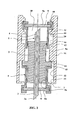
- a connector perforating device comprises a hollow needle 1 with an axial channel 1 a of fluid passage, a needle support body 2 which surrounds and is fixed so sealed to an intermediate portion of the needle 1, and which allows to pass a first end section 3 and a second end section 4 of the needle 1.
- the first end portion 3 of the needle 1 is surrounded by a first tubular receptacle 5 closed by a first operculum 6. In this way, initial position or transport position illustrated in Figure 1, the first section end 3 of the needle 1 remains confined in a first cavity 7 limited by the first operculum 6, by the first tubular receptacle 5 and the body 2.
- a second tubular receptacle 8 surrounds the second section end 4 of the needle 1 and is closed by a second operculum 9.
- the second section 4 end of the needle 1 is confined in a second cavity 10 limited by the second operculum 9, by the second tubular receptacle 8 and the body 2.
- the first tubular receptacle 5 is shaped to be coupled to a first container to be connected, for example by being applied axially against a lid or cap of a first bottle.
- the second tubular receptacle 8 is shaped to be coupled to a second container to be connected; for example by being applied axially against a second cap or cap of a second vial.
- the assembly formed by the first cap 6 and the first receptacle tubular 5 can slide on the body 2, so that the first seal 6 is axially displaceable relative to the body 2 needle support according to a first C1 piercing stroke:
- the first piercing stroke C1 is defined as being the axial translational movement of the first cap 6 from a position initial embodiment, illustrated in FIG. 1, in which the first lid 6 is away from the body 2 and the needle 1, to a final position, illustrated in FIG. which the first operculum 6 is close to the body 2, the needle 1 passes through the first cap 6 and its end 3a protrudes outwardly of the connector.
- the assembly formed by the second operculum 9 and the second tubular receptacle 8 can slide on the body 2, so that the second opercule 9 is axially displaceable relative to the body 2 needle support in a second drilling stroke C2 ( Figure 3).
- the second race of drilling C2 is defined as the axial translation movement of the second opercule 9 from an initial position, illustrated in FIGS. 1 to 3, in which the second cap 9 is away from the body 2 and the needle 1, to a position end, illustrated in FIG. 4, in which the second cap 9 is brought closer to the body 2, the needle 1 passes through the second operculum 9 and its end 4a protrudes towards the outside of the connector.
- the two lids 6 and 9 are movable independently of one of the other towards and away from the body 2.
- the first cap 6 is thus mounted on a first receptacle tubular 5 itself in the form of a first cylinder which slides on the body 2 with interposition of first sealed sliding means 5a, for example a plurality of annular ribs provided on the body 2.
- the second cap 9 is mounted on a second receptacle tubular 8 in the form of a cylinder which slides on the body 2 with the interposition of sealed sliding means 8a, for example a plurality of ribs rings provided on the body 2.
- An outer coaxial sleeve 11 is provided to constitute a means of gripping for axially moving the body 2 towards the first operculum 6 according to a distance equal to the first piercing stroke C1 by causing the second operculum 9, then to axially move the second cap 9 to the body 2 and towards the first cap 6 according to the second piercing stroke C2.
- the sleeve 11 comprises for this means unilateral engagement means to axially push the body 2 towards the first lid 6, so that the sleeve 11 performs the first drilling stroke towards the body 2, that is to say the illustrated run from Figure 1 to Figure 2.
- the first cap 6 is in axial support against a first container, so that it undergoes a relative movement towards the body 2 according to said first piercing stroke.
- the means of unilateral engagement allow the sleeve 11 to reverse reversing stroke of the first piercing stroke, out of the way of the first operculum 6, that is to say, to move from the position of FIG. position of Figure 3.
- the second operculum 9 is in axial support against a second container, and non-return engagement means of the sleeve 11 hold the second cap 9 in a fixed position relative to the body 2 allowing its sliding in the sleeve 11.
- the sleeve 11 comprises a first bore 12 of larger diameter, provided in a section of first end of the sleeve 11, and limited by a first shoulder 13 and a second shoulder 14.
- the body 2 comprises an annular rib 15 of larger diameter, engaged in the first bore 12 of the sleeve 11 to allow the relative axial displacement of the sleeve 11 around the body 2 according to a race appropriately equal to the first piercing stroke C1.
- the annular rib 15 abuts on one or the other of the shoulders 13 or 14.
- the sleeve 11 comprises a second bore of larger diameter 16, provided in a section of second end of the sleeve 11, and limited by a third shoulder 17 and a fourth shoulder 18.
- the second cap 9 remains engaged in the second bore 16 for move in an appropriate axial stroke equal to the second piercing stroke C2.
- the second bore 16 comprises an intermediate annular rib 19 having a sawtooth transverse profile having a first right face and a second face 21 oblique.
- the second tubular receptacle 8 in the form of a second cylinder slides in the sleeve 11.
- the first cylinder exceeds outside the sleeve 11, so that the first cap 6 presents a first external face 6a accessible for disinfection.
- the second cylinder 8 is engaged in the sleeve 11 while having the second operculum 9 in the vicinity of the second end of the sleeve 11, so that the outer face 9a of the second cap 9 is also accessible by the user for disinfection.
- the connector is in the state shown in Figure 1: the first cylindrical tubular receptacle 5 is away from the body 2 and protrudes outside the sleeve 11, the first end portion 3 of the needle 1 being confined in the first cavity 7 set back from the first lid 6.
- second tubular receptacle 8 is engaged in the sleeve 11 in the vicinity of its second end, the second operculum 9 being engaged between the fourth shoulder 18 and the intermediate rib 19, and being away from the body 2.
- the second end section 4 of the needle 1 is then confined in the second cavity 10.
- the lid or cap of a first container is engaged against the first operculum 6, and the perforating connector is pushed by its sleeve 11 against the first bottle, that is to say downwards in Figure 1.
- the shoulder 18 also causes the second operculum 9 in the same race, in the same movement as the body 2, the needle 1 thus remaining always set back from the second lid 9.
- the sleeve 11 is then brought back in a recoil stroke, as illustrated in FIG. 3.
- the second operculum 9 selected in axial support against the operculum or cap of a second container, lets pass the intermediate rib 19, thanks to the asymmetrical shape of the rib and to a elastic radial deformation of the rib 19 and / or the operculum 9, and engage under the right face 20 of this intermediate rib 19.
Landscapes
- Health & Medical Sciences (AREA)
- Pharmacology & Pharmacy (AREA)
- Life Sciences & Earth Sciences (AREA)
- Animal Behavior & Ethology (AREA)
- General Health & Medical Sciences (AREA)
- Public Health (AREA)
- Veterinary Medicine (AREA)
- Infusion, Injection, And Reservoir Apparatuses (AREA)
- Pharmaceuticals Containing Other Organic And Inorganic Compounds (AREA)
- Medicines That Contain Protein Lipid Enzymes And Other Medicines (AREA)
- Medicines Containing Material From Animals Or Micro-Organisms (AREA)
- Prostheses (AREA)
- Separation Using Semi-Permeable Membranes (AREA)
Applications Claiming Priority (2)
| Application Number | Priority Date | Filing Date | Title |
|---|---|---|---|
| FR0402568 | 2004-03-10 | ||
| FR0402568A FR2867396B1 (fr) | 2004-03-10 | 2004-03-10 | Performeur perforant a connexion sterile |
Publications (2)
| Publication Number | Publication Date |
|---|---|
| EP1574200A1 true EP1574200A1 (de) | 2005-09-14 |
| EP1574200B1 EP1574200B1 (de) | 2006-11-02 |
Family
ID=34814576
Family Applications (1)
| Application Number | Title | Priority Date | Filing Date |
|---|---|---|---|
| EP20050356039 Expired - Lifetime EP1574200B1 (de) | 2004-03-10 | 2005-03-02 | Eine sterile Verbindung herstellender Perforationsverbinder |
Country Status (6)
| Country | Link |
|---|---|
| US (1) | US7297140B2 (de) |
| EP (1) | EP1574200B1 (de) |
| AT (1) | ATE344000T1 (de) |
| CA (1) | CA2500562A1 (de) |
| DE (1) | DE602005000215T2 (de) |
| FR (1) | FR2867396B1 (de) |
Cited By (3)
| Publication number | Priority date | Publication date | Assignee | Title |
|---|---|---|---|---|
| EP2090278A1 (de) * | 2008-02-18 | 2009-08-19 | P2A Medical | Deckelsystem zur Übertragung |
| WO2014053430A1 (de) * | 2012-10-01 | 2014-04-10 | Medac Gesellschaft für klinische Spezialpräparate mbH | Transfervorrichtung zur entnahme oder übergabe eines fluids |
| WO2015160522A1 (en) * | 2014-04-15 | 2015-10-22 | Advanced Scientifics, Inc. | Aseptic connector |
Families Citing this family (77)
| Publication number | Priority date | Publication date | Assignee | Title |
|---|---|---|---|---|
| US8562583B2 (en) | 2002-03-26 | 2013-10-22 | Carmel Pharma Ab | Method and assembly for fluid transfer and drug containment in an infusion system |
| US7867215B2 (en) * | 2002-04-17 | 2011-01-11 | Carmel Pharma Ab | Method and device for fluid transfer in an infusion system |
| SE523001C2 (sv) | 2002-07-09 | 2004-03-23 | Carmel Pharma Ab | En kopplingsdel, en koppling, en infusionspåse, en infusionsanordning och ett förfarande för överföring av medicinska substanser |
| JP5148107B2 (ja) | 2003-01-21 | 2013-02-20 | カルメル ファルマ アクチボラゲット | 膜を突き刺すための針 |
| US8784336B2 (en) | 2005-08-24 | 2014-07-22 | C. R. Bard, Inc. | Stylet apparatuses and methods of manufacture |
| US7547300B2 (en) | 2006-04-12 | 2009-06-16 | Icu Medical, Inc. | Vial adaptor for regulating pressure |
| NZ573048A (en) | 2006-05-25 | 2011-08-26 | Bayer Healthcare Llc | Reconstitution device |
| US7670326B2 (en) * | 2006-09-25 | 2010-03-02 | Teva Medical Ltd.. | Syringe adapter element in drug mixing system |
| US8388546B2 (en) | 2006-10-23 | 2013-03-05 | Bard Access Systems, Inc. | Method of locating the tip of a central venous catheter |
| US7794407B2 (en) | 2006-10-23 | 2010-09-14 | Bard Access Systems, Inc. | Method of locating the tip of a central venous catheter |
| US7883499B2 (en) | 2007-03-09 | 2011-02-08 | Icu Medical, Inc. | Vial adaptors and vials for regulating pressure |
| US7942860B2 (en) * | 2007-03-16 | 2011-05-17 | Carmel Pharma Ab | Piercing member protection device |
| US7975733B2 (en) * | 2007-05-08 | 2011-07-12 | Carmel Pharma Ab | Fluid transfer device |
| US8622985B2 (en) | 2007-06-13 | 2014-01-07 | Carmel Pharma Ab | Arrangement for use with a medical device |
| US8657803B2 (en) | 2007-06-13 | 2014-02-25 | Carmel Pharma Ab | Device for providing fluid to a receptacle |
| US8029747B2 (en) | 2007-06-13 | 2011-10-04 | Carmel Pharma Ab | Pressure equalizing device, receptacle and method |
| US10398834B2 (en) | 2007-08-30 | 2019-09-03 | Carmel Pharma Ab | Device, sealing member and fluid container |
| US8287513B2 (en) | 2007-09-11 | 2012-10-16 | Carmel Pharma Ab | Piercing member protection device |
| DE102007046951B3 (de) * | 2007-10-01 | 2009-02-26 | B. Braun Melsungen Ag | Vorrichtung zum Einführen eines Medikaments in einen Infusionsbehälter |
| ES2557084T3 (es) | 2007-11-26 | 2016-01-21 | C. R. Bard, Inc. | Sistema integrado para la colocación intravascular de un catéter |
| US8849382B2 (en) | 2007-11-26 | 2014-09-30 | C. R. Bard, Inc. | Apparatus and display methods relating to intravascular placement of a catheter |
| US8781555B2 (en) | 2007-11-26 | 2014-07-15 | C. R. Bard, Inc. | System for placement of a catheter including a signal-generating stylet |
| US9492097B2 (en) | 2007-11-26 | 2016-11-15 | C. R. Bard, Inc. | Needle length determination and calibration for insertion guidance system |
| US9521961B2 (en) | 2007-11-26 | 2016-12-20 | C. R. Bard, Inc. | Systems and methods for guiding a medical instrument |
| US10751509B2 (en) | 2007-11-26 | 2020-08-25 | C. R. Bard, Inc. | Iconic representations for guidance of an indwelling medical device |
| US10524691B2 (en) | 2007-11-26 | 2020-01-07 | C. R. Bard, Inc. | Needle assembly including an aligned magnetic element |
| US9649048B2 (en) | 2007-11-26 | 2017-05-16 | C. R. Bard, Inc. | Systems and methods for breaching a sterile field for intravascular placement of a catheter |
| US10449330B2 (en) | 2007-11-26 | 2019-10-22 | C. R. Bard, Inc. | Magnetic element-equipped needle assemblies |
| US8478382B2 (en) | 2008-02-11 | 2013-07-02 | C. R. Bard, Inc. | Systems and methods for positioning a catheter |
| CA2721715C (en) * | 2008-04-17 | 2018-01-30 | C.R. Bard, Inc. | Systems and methods for breaching a sterile field for intravascular placement of a catheter |
| US8075550B2 (en) | 2008-07-01 | 2011-12-13 | Carmel Pharma Ab | Piercing member protection device |
| WO2010022095A1 (en) * | 2008-08-20 | 2010-02-25 | Icu Medical, Inc. | Anti-reflux vial adaptors |
| ES2525525T3 (es) | 2008-08-22 | 2014-12-26 | C.R. Bard, Inc. | Conjunto de catéter que incluye conjuntos de sensor de ECG y magnético |
| US8437833B2 (en) | 2008-10-07 | 2013-05-07 | Bard Access Systems, Inc. | Percutaneous magnetic gastrostomy |
| US8523838B2 (en) | 2008-12-15 | 2013-09-03 | Carmel Pharma Ab | Connector device |
| US8790330B2 (en) | 2008-12-15 | 2014-07-29 | Carmel Pharma Ab | Connection arrangement and method for connecting a medical device to the improved connection arrangement |
| US9339206B2 (en) | 2009-06-12 | 2016-05-17 | Bard Access Systems, Inc. | Adaptor for endovascular electrocardiography |
| US9532724B2 (en) | 2009-06-12 | 2017-01-03 | Bard Access Systems, Inc. | Apparatus and method for catheter navigation using endovascular energy mapping |
| EP2464407A4 (de) | 2009-08-10 | 2014-04-02 | Bard Access Systems Inc | Vorrichtungen und verfahren für endovaskuläre elektrographie |
| US8281807B2 (en) | 2009-08-31 | 2012-10-09 | Medrad, Inc. | Fluid path connectors and container spikes for fluid delivery |
| JP5981341B2 (ja) * | 2009-09-14 | 2016-08-31 | ネステク ソシエテ アノニム | ホイルシールと貫通手段を伴う包装体 |
| CN102665541B (zh) | 2009-09-29 | 2016-01-13 | C·R·巴德股份有限公司 | 与用于导管的血管内放置的设备一起使用的探针 |
| WO2011044421A1 (en) | 2009-10-08 | 2011-04-14 | C. R. Bard, Inc. | Spacers for use with an ultrasound probe |
| USD637713S1 (en) | 2009-11-20 | 2011-05-10 | Carmel Pharma Ab | Medical device adaptor |
| US8480646B2 (en) | 2009-11-20 | 2013-07-09 | Carmel Pharma Ab | Medical device connector |
| WO2011097312A1 (en) | 2010-02-02 | 2011-08-11 | C.R. Bard, Inc. | Apparatus and method for catheter navigation and tip location |
| US9168203B2 (en) | 2010-05-21 | 2015-10-27 | Carmel Pharma Ab | Connectors for fluid containers |
| US8162013B2 (en) | 2010-05-21 | 2012-04-24 | Tobias Rosenquist | Connectors for fluid containers |
| CN103037761B (zh) | 2010-05-28 | 2016-11-02 | C·R·巴德股份有限公司 | 用于针和医疗部件的插入引导系统 |
| EP2912999B1 (de) | 2010-05-28 | 2022-06-29 | C. R. Bard, Inc. | Vorrichtung zur Verwendung mit einem Nadeleinsatz-Führungssystem |
| EP2603145A2 (de) | 2010-08-09 | 2013-06-19 | C.R. Bard, Inc. | Stütz- und abdeckungsstrukturen für einen ultraschallsondenkopf |
| JP5845260B2 (ja) | 2010-08-20 | 2016-01-20 | シー・アール・バード・インコーポレーテッドC R Bard Incorporated | Ecg支援カテーテル先端配置の再確認 |
| WO2012058461A1 (en) | 2010-10-29 | 2012-05-03 | C.R.Bard, Inc. | Bioimpedance-assisted placement of a medical device |
| IT1403142B1 (it) * | 2010-11-19 | 2013-10-04 | Borla Ind | Dispositivo di miscelazione di fluidi medicali e relativo procedimento di assemblaggio. |
| USD699359S1 (en) | 2011-08-09 | 2014-02-11 | C. R. Bard, Inc. | Ultrasound probe head |
| USD724745S1 (en) | 2011-08-09 | 2015-03-17 | C. R. Bard, Inc. | Cap for an ultrasound probe |
| JP6541349B2 (ja) | 2011-08-18 | 2019-07-10 | アイシーユー・メディカル・インコーポレーテッド | 圧力調節バイアルアダプタ |
| WO2013070775A1 (en) | 2011-11-07 | 2013-05-16 | C.R. Bard, Inc | Ruggedized ultrasound hydrogel insert |
| MX352988B (es) | 2012-01-13 | 2017-12-15 | Icu Medical Inc | Adaptadores de frasco reguladores de presión y métodos. |
| AU2013204180B2 (en) | 2012-03-22 | 2016-07-21 | Icu Medical, Inc. | Pressure-regulating vial adaptors |
| CN104837413B (zh) | 2012-06-15 | 2018-09-11 | C·R·巴德股份有限公司 | 检测超声探测器上可移除帽的装置及方法 |
| DK2948125T3 (da) | 2013-01-23 | 2019-08-19 | Icu Medical Inc | Trykregulerende hætteglasadaptorer |
| US9089475B2 (en) | 2013-01-23 | 2015-07-28 | Icu Medical, Inc. | Pressure-regulating vial adaptors |
| EP3021814B1 (de) | 2013-07-19 | 2025-03-26 | ICU Medical, Inc. | Druckregelnde flüssigkeitsübertragungssysteme und verfahren |
| CN105979868B (zh) | 2014-02-06 | 2020-03-10 | C·R·巴德股份有限公司 | 用于血管内装置的导向和放置的系统和方法 |
| KR101639329B1 (ko) * | 2014-06-20 | 2016-07-22 | 대한약품공업 주식회사 | 위생안전 보증형 약병 접속소켓과 이를 포함하는 수액 제품 |
| JP6605511B2 (ja) | 2014-06-20 | 2019-11-13 | アイシーユー・メディカル・インコーポレーテッド | 圧力調整バイアルアダプタ |
| US10973584B2 (en) | 2015-01-19 | 2021-04-13 | Bard Access Systems, Inc. | Device and method for vascular access |
| WO2016210325A1 (en) | 2015-06-26 | 2016-12-29 | C.R. Bard, Inc. | Connector interface for ecg-based catheter positioning system |
| EP3397231B1 (de) | 2016-01-29 | 2022-03-02 | ICU Medical, Inc. | Druckregelungsadapter für eine phiole |
| US11000207B2 (en) | 2016-01-29 | 2021-05-11 | C. R. Bard, Inc. | Multiple coil system for tracking a medical device |
| AU2017335746A1 (en) | 2016-09-30 | 2019-04-11 | Icu Medical, Inc. | Pressure-regulating vial access devices and methods |
| JP7171037B2 (ja) * | 2018-04-19 | 2022-11-15 | 内外化成株式会社 | 移注部材及びその製造方法 |
| US11090227B2 (en) * | 2018-06-01 | 2021-08-17 | Bio-Rad Laboratories, Inc. | Connector for transferring the contents of a container |
| EP3852622B1 (de) | 2018-10-16 | 2025-04-02 | Bard Access Systems, Inc. | Sicherheitsausgerüstete verbindungssysteme und verfahren dafür zur herstellung von elektrischen verbindungen |
| CN113473916A (zh) | 2019-01-30 | 2021-10-01 | 巴德阿克塞斯系统股份有限公司 | 用于跟踪医疗装置的系统和方法 |
| GB201918663D0 (en) | 2019-12-17 | 2020-01-29 | Oribiotech Ltd | A connector |
Citations (2)
| Publication number | Priority date | Publication date | Assignee | Title |
|---|---|---|---|---|
| WO2003082398A2 (en) | 2002-03-26 | 2003-10-09 | Baxter International Inc. | Sliding reconstitution device for a diluent container |
| US20030199846A1 (en) | 1998-09-15 | 2003-10-23 | Baxter International Inc. | Sliding reconstitution device for a diluent container |
Family Cites Families (4)
| Publication number | Priority date | Publication date | Assignee | Title |
|---|---|---|---|---|
| JP2605345Y2 (ja) * | 1992-05-01 | 2000-07-10 | 株式会社大塚製薬工場 | 薬剤容器 |
| JPH06239352A (ja) * | 1993-02-05 | 1994-08-30 | Nissho Corp | 溶解液注入セット |
| FR2738550B1 (fr) * | 1995-09-11 | 1997-11-07 | Biodome | Dispositif d'obturation d'un recipient lui-meme ferme, ensemble pour dispenser un produit comprenant un tel recipient et un tel dispositif d'obturation |
| US6019750A (en) * | 1997-12-04 | 2000-02-01 | Baxter International Inc. | Sliding reconstitution device with seal |
-
2004
- 2004-03-10 FR FR0402568A patent/FR2867396B1/fr not_active Expired - Fee Related
-
2005
- 2005-02-28 US US11/068,236 patent/US7297140B2/en not_active Expired - Fee Related
- 2005-03-02 DE DE200560000215 patent/DE602005000215T2/de not_active Expired - Fee Related
- 2005-03-02 EP EP20050356039 patent/EP1574200B1/de not_active Expired - Lifetime
- 2005-03-02 AT AT05356039T patent/ATE344000T1/de not_active IP Right Cessation
- 2005-03-07 CA CA 2500562 patent/CA2500562A1/fr not_active Abandoned
Patent Citations (2)
| Publication number | Priority date | Publication date | Assignee | Title |
|---|---|---|---|---|
| US20030199846A1 (en) | 1998-09-15 | 2003-10-23 | Baxter International Inc. | Sliding reconstitution device for a diluent container |
| WO2003082398A2 (en) | 2002-03-26 | 2003-10-09 | Baxter International Inc. | Sliding reconstitution device for a diluent container |
Cited By (8)
| Publication number | Priority date | Publication date | Assignee | Title |
|---|---|---|---|---|
| EP2090278A1 (de) * | 2008-02-18 | 2009-08-19 | P2A Medical | Deckelsystem zur Übertragung |
| FR2927533A1 (fr) * | 2008-02-18 | 2009-08-21 | P2A Medical Soc Par Actions Si | Capuchon de transfert securise |
| WO2014053430A1 (de) * | 2012-10-01 | 2014-04-10 | Medac Gesellschaft für klinische Spezialpräparate mbH | Transfervorrichtung zur entnahme oder übergabe eines fluids |
| US10058482B2 (en) | 2012-10-01 | 2018-08-28 | Medac Gesellschaft Fur Klinische Spezialpraparate Mbh | Transfer device for tapping or delivering a fluid |
| WO2015160522A1 (en) * | 2014-04-15 | 2015-10-22 | Advanced Scientifics, Inc. | Aseptic connector |
| US9186493B2 (en) | 2014-04-15 | 2015-11-17 | Advanced Scientific, Inc. | Aseptic connector |
| US10111809B2 (en) | 2014-04-15 | 2018-10-30 | Advanced Scientifics, Inc. | Aseptic connector and method |
| US11191700B2 (en) | 2014-04-15 | 2021-12-07 | Advanced Scientifics, Inc. | Aseptic connector |
Also Published As
| Publication number | Publication date |
|---|---|
| ATE344000T1 (de) | 2006-11-15 |
| CA2500562A1 (fr) | 2005-09-10 |
| FR2867396B1 (fr) | 2006-12-22 |
| DE602005000215D1 (de) | 2006-12-14 |
| FR2867396A1 (fr) | 2005-09-16 |
| EP1574200B1 (de) | 2006-11-02 |
| DE602005000215T2 (de) | 2007-08-30 |
| US7297140B2 (en) | 2007-11-20 |
| US20050203481A1 (en) | 2005-09-15 |
Similar Documents
| Publication | Publication Date | Title |
|---|---|---|
| EP1574200B1 (de) | Eine sterile Verbindung herstellender Perforationsverbinder | |
| EP0448656B1 (de) | Länglicher behälter mit zwei getrennten kammern auf der gleichen längsachse | |
| EP1076575B1 (de) | Vorrichtung zum schutz und zur neutralisation einer nadel zum medizinischen gebrauch | |
| EP1744717B1 (de) | Spritze für medizinische eingriffe und diese enthaltender kit zur rekonstitution unvorbereiteter substanzen | |
| FR2927533A1 (fr) | Capuchon de transfert securise | |
| FR2725902A1 (fr) | Dispositif de protection pour une aiguille tubulaire | |
| EP1967335A1 (de) | Vorrichtung zum Auswechseln eines Handschuhs eines Handschuhkastens für die Handhabung in einem abgeschlossenen Raum und zugehöriges Verfahren zur Handschuhauswechselung | |
| EP2504102B1 (de) | Gehäuse für dichte verbindungsvorrichtung und aseptische transfervorrichtung | |
| EP3042382A1 (de) | Vorrichtung zur bereitstellung einer fluiddichten verbindung mit verbesserter betriebssicherheit | |
| FR2952988A1 (fr) | Perfectionnements a la jonction etanche et au transfert etanche entre deux enceintes en vue d'un transfert aseptique entre elles. | |
| FR2714824A1 (fr) | Dispositif à carpule pour la distribution d'un liquide. | |
| FR2911493A1 (fr) | Procede et set de transfert d'un fluide entre deux recipients. | |
| EP0123598A1 (de) | Drehbarer Transport- und Ersatzbehälter für verunreinigte Teile und Ergänzungsetui für diesen Behälter | |
| EP1523359A2 (de) | Injektions- oder zerstäubungsvorrichtung, insbesondere zum medizinischen gebrauch | |
| FR2671730A1 (fr) | Dispositif de conditionnement et de distribution d'instruments medicaux pointus ou tranchants tels que des aiguilles ou des lames de bistouris. | |
| FR3095360A1 (fr) | Isolateur jetable et installation de conditionnement de produits comprenant un tel isolateur jetable | |
| EP3259760B1 (de) | Vorrichtung zur ermöglichung der übertragung zwischen einem behälter und einer zelle sowie verfahren zur verwendung | |
| FR2943532A1 (fr) | Systemes a poches comprenant un recipient d'echantillonnage muni d'un dispositif d'ouverture | |
| FR2718644A1 (fr) | Dispositif d'injection à aiguille rétractable. | |
| EP0380500B1 (de) | Vorrichtung zum befüllen in kontrollierter atmosphäre | |
| EP0530071A1 (de) | Ampulle mit vollständiger Füllung und angepasste Spritze für die Konservierung von flüssigen Produkten mit pharmazeutischen medizinischen oder industriellen Eigenschaften | |
| EP0976419A1 (de) | Verbindungsvorrichtung für eine Peritonealdialyseleitung | |
| FR2776165A1 (fr) | Dispositif d'implantation de puce transpondeur d'identification pour animaux | |
| FR2830785A1 (fr) | Procede et instrument pour deverrouiller un dispositif comportant deux corps encliquetes axialement | |
| EP4115977A1 (de) | Anlage zur herstellung eines zentrifugierten produkts sowie entsprechendes herstellungsverfahren unter verwendung einer solchen anlage |
Legal Events
| Date | Code | Title | Description |
|---|---|---|---|
| PUAI | Public reference made under article 153(3) epc to a published international application that has entered the european phase |
Free format text: ORIGINAL CODE: 0009012 |
|
| AK | Designated contracting states |
Kind code of ref document: A1 Designated state(s): AT BE BG CH CY CZ DE DK EE ES FI FR GB GR HU IE IS IT LI LT LU MC NL PL PT RO SE SI SK TR |
|
| AX | Request for extension of the european patent |
Extension state: AL BA HR LV MK YU |
|
| 17P | Request for examination filed |
Effective date: 20060308 |
|
| GRAP | Despatch of communication of intention to grant a patent |
Free format text: ORIGINAL CODE: EPIDOSNIGR1 |
|
| AKX | Designation fees paid |
Designated state(s): AT BE BG CH CY CZ DE DK EE ES FI FR GB GR HU IE IS IT LI LT LU MC NL PL PT RO SE SI SK TR |
|
| GRAS | Grant fee paid |
Free format text: ORIGINAL CODE: EPIDOSNIGR3 |
|
| GRAA | (expected) grant |
Free format text: ORIGINAL CODE: 0009210 |
|
| AK | Designated contracting states |
Kind code of ref document: B1 Designated state(s): AT BE BG CH CY CZ DE DK EE ES FI FR GB GR HU IE IS IT LI LT LU MC NL PL PT RO SE SI SK TR |
|
| PG25 | Lapsed in a contracting state [announced via postgrant information from national office to epo] |
Ref country code: NL Free format text: LAPSE BECAUSE OF FAILURE TO SUBMIT A TRANSLATION OF THE DESCRIPTION OR TO PAY THE FEE WITHIN THE PRESCRIBED TIME-LIMIT Effective date: 20061102 Ref country code: IT Free format text: LAPSE BECAUSE OF FAILURE TO SUBMIT A TRANSLATION OF THE DESCRIPTION OR TO PAY THE FEE WITHIN THE PRESCRIBED TIME-LIMIT;WARNING: LAPSES OF ITALIAN PATENTS WITH EFFECTIVE DATE BEFORE 2007 MAY HAVE OCCURRED AT ANY TIME BEFORE 2007. THE CORRECT EFFECTIVE DATE MAY BE DIFFERENT FROM THE ONE RECORDED. Effective date: 20061102 Ref country code: RO Free format text: LAPSE BECAUSE OF FAILURE TO SUBMIT A TRANSLATION OF THE DESCRIPTION OR TO PAY THE FEE WITHIN THE PRESCRIBED TIME-LIMIT Effective date: 20061102 Ref country code: CZ Free format text: LAPSE BECAUSE OF FAILURE TO SUBMIT A TRANSLATION OF THE DESCRIPTION OR TO PAY THE FEE WITHIN THE PRESCRIBED TIME-LIMIT Effective date: 20061102 Ref country code: SK Free format text: LAPSE BECAUSE OF FAILURE TO SUBMIT A TRANSLATION OF THE DESCRIPTION OR TO PAY THE FEE WITHIN THE PRESCRIBED TIME-LIMIT Effective date: 20061102 Ref country code: PL Free format text: LAPSE BECAUSE OF FAILURE TO SUBMIT A TRANSLATION OF THE DESCRIPTION OR TO PAY THE FEE WITHIN THE PRESCRIBED TIME-LIMIT Effective date: 20061102 Ref country code: FI Free format text: LAPSE BECAUSE OF FAILURE TO SUBMIT A TRANSLATION OF THE DESCRIPTION OR TO PAY THE FEE WITHIN THE PRESCRIBED TIME-LIMIT Effective date: 20061102 Ref country code: AT Free format text: LAPSE BECAUSE OF FAILURE TO SUBMIT A TRANSLATION OF THE DESCRIPTION OR TO PAY THE FEE WITHIN THE PRESCRIBED TIME-LIMIT Effective date: 20061102 Ref country code: LT Free format text: LAPSE BECAUSE OF FAILURE TO SUBMIT A TRANSLATION OF THE DESCRIPTION OR TO PAY THE FEE WITHIN THE PRESCRIBED TIME-LIMIT Effective date: 20061102 Ref country code: IE Free format text: LAPSE BECAUSE OF FAILURE TO SUBMIT A TRANSLATION OF THE DESCRIPTION OR TO PAY THE FEE WITHIN THE PRESCRIBED TIME-LIMIT Effective date: 20061102 Ref country code: SI Free format text: LAPSE BECAUSE OF FAILURE TO SUBMIT A TRANSLATION OF THE DESCRIPTION OR TO PAY THE FEE WITHIN THE PRESCRIBED TIME-LIMIT Effective date: 20061102 |
|
| REG | Reference to a national code |
Ref country code: GB Ref legal event code: FG4D Free format text: NOT ENGLISH |
|
| REG | Reference to a national code |
Ref country code: IE Ref legal event code: FG4D Free format text: LANGUAGE OF EP DOCUMENT: FRENCH |
|
| REG | Reference to a national code |
Ref country code: CH Ref legal event code: EP |
|
| REF | Corresponds to: |
Ref document number: 602005000215 Country of ref document: DE Date of ref document: 20061214 Kind code of ref document: P |
|
| PG25 | Lapsed in a contracting state [announced via postgrant information from national office to epo] |
Ref country code: BG Free format text: LAPSE BECAUSE OF FAILURE TO SUBMIT A TRANSLATION OF THE DESCRIPTION OR TO PAY THE FEE WITHIN THE PRESCRIBED TIME-LIMIT Effective date: 20070202 Ref country code: SE Free format text: LAPSE BECAUSE OF FAILURE TO SUBMIT A TRANSLATION OF THE DESCRIPTION OR TO PAY THE FEE WITHIN THE PRESCRIBED TIME-LIMIT Effective date: 20070202 Ref country code: DK Free format text: LAPSE BECAUSE OF FAILURE TO SUBMIT A TRANSLATION OF THE DESCRIPTION OR TO PAY THE FEE WITHIN THE PRESCRIBED TIME-LIMIT Effective date: 20070202 |
|
| PG25 | Lapsed in a contracting state [announced via postgrant information from national office to epo] |
Ref country code: ES Free format text: LAPSE BECAUSE OF FAILURE TO SUBMIT A TRANSLATION OF THE DESCRIPTION OR TO PAY THE FEE WITHIN THE PRESCRIBED TIME-LIMIT Effective date: 20070213 |
|
| GBT | Gb: translation of ep patent filed (gb section 77(6)(a)/1977) |
Effective date: 20070205 |
|
| PG25 | Lapsed in a contracting state [announced via postgrant information from national office to epo] |
Ref country code: IS Free format text: LAPSE BECAUSE OF FAILURE TO SUBMIT A TRANSLATION OF THE DESCRIPTION OR TO PAY THE FEE WITHIN THE PRESCRIBED TIME-LIMIT Effective date: 20070302 |
|
| PG25 | Lapsed in a contracting state [announced via postgrant information from national office to epo] |
Ref country code: PT Free format text: LAPSE BECAUSE OF FAILURE TO SUBMIT A TRANSLATION OF THE DESCRIPTION OR TO PAY THE FEE WITHIN THE PRESCRIBED TIME-LIMIT Effective date: 20070402 |
|
| NLV1 | Nl: lapsed or annulled due to failure to fulfill the requirements of art. 29p and 29m of the patents act | ||
| PGFP | Annual fee paid to national office [announced via postgrant information from national office to epo] |
Ref country code: DE Payment date: 20070530 Year of fee payment: 3 |
|
| REG | Reference to a national code |
Ref country code: IE Ref legal event code: FD4D |
|
| PLBE | No opposition filed within time limit |
Free format text: ORIGINAL CODE: 0009261 |
|
| STAA | Information on the status of an ep patent application or granted ep patent |
Free format text: STATUS: NO OPPOSITION FILED WITHIN TIME LIMIT |
|
| 26N | No opposition filed |
Effective date: 20070803 |
|
| BERE | Be: lapsed |
Owner name: P2A MEDICAL Effective date: 20070331 |
|
| PG25 | Lapsed in a contracting state [announced via postgrant information from national office to epo] |
Ref country code: BE Free format text: LAPSE BECAUSE OF NON-PAYMENT OF DUE FEES Effective date: 20070331 |
|
| PG25 | Lapsed in a contracting state [announced via postgrant information from national office to epo] |
Ref country code: MC Free format text: LAPSE BECAUSE OF NON-PAYMENT OF DUE FEES Effective date: 20070331 |
|
| PG25 | Lapsed in a contracting state [announced via postgrant information from national office to epo] |
Ref country code: GR Free format text: LAPSE BECAUSE OF FAILURE TO SUBMIT A TRANSLATION OF THE DESCRIPTION OR TO PAY THE FEE WITHIN THE PRESCRIBED TIME-LIMIT Effective date: 20070203 |
|
| PG25 | Lapsed in a contracting state [announced via postgrant information from national office to epo] |
Ref country code: EE Free format text: LAPSE BECAUSE OF FAILURE TO SUBMIT A TRANSLATION OF THE DESCRIPTION OR TO PAY THE FEE WITHIN THE PRESCRIBED TIME-LIMIT Effective date: 20061102 Ref country code: DE Free format text: LAPSE BECAUSE OF NON-PAYMENT OF DUE FEES Effective date: 20081001 |
|
| PG25 | Lapsed in a contracting state [announced via postgrant information from national office to epo] |
Ref country code: LU Free format text: LAPSE BECAUSE OF NON-PAYMENT OF DUE FEES Effective date: 20070302 Ref country code: CY Free format text: LAPSE BECAUSE OF FAILURE TO SUBMIT A TRANSLATION OF THE DESCRIPTION OR TO PAY THE FEE WITHIN THE PRESCRIBED TIME-LIMIT Effective date: 20061102 |
|
| PG25 | Lapsed in a contracting state [announced via postgrant information from national office to epo] |
Ref country code: TR Free format text: LAPSE BECAUSE OF FAILURE TO SUBMIT A TRANSLATION OF THE DESCRIPTION OR TO PAY THE FEE WITHIN THE PRESCRIBED TIME-LIMIT Effective date: 20061102 Ref country code: HU Free format text: LAPSE BECAUSE OF FAILURE TO SUBMIT A TRANSLATION OF THE DESCRIPTION OR TO PAY THE FEE WITHIN THE PRESCRIBED TIME-LIMIT Effective date: 20070503 |
|
| REG | Reference to a national code |
Ref country code: CH Ref legal event code: PL |
|
| PG25 | Lapsed in a contracting state [announced via postgrant information from national office to epo] |
Ref country code: LI Free format text: LAPSE BECAUSE OF NON-PAYMENT OF DUE FEES Effective date: 20090331 Ref country code: CH Free format text: LAPSE BECAUSE OF NON-PAYMENT OF DUE FEES Effective date: 20090331 |
|
| PGFP | Annual fee paid to national office [announced via postgrant information from national office to epo] |
Ref country code: GB Payment date: 20100318 Year of fee payment: 6 |
|
| GBPC | Gb: european patent ceased through non-payment of renewal fee |
Effective date: 20110302 |
|
| REG | Reference to a national code |
Ref country code: FR Ref legal event code: CA Effective date: 20120118 |
|
| PG25 | Lapsed in a contracting state [announced via postgrant information from national office to epo] |
Ref country code: GB Free format text: LAPSE BECAUSE OF NON-PAYMENT OF DUE FEES Effective date: 20110302 |
|
| REG | Reference to a national code |
Ref country code: FR Ref legal event code: PLFP Year of fee payment: 12 |
|
| PGFP | Annual fee paid to national office [announced via postgrant information from national office to epo] |
Ref country code: FR Payment date: 20160321 Year of fee payment: 12 |
|
| REG | Reference to a national code |
Ref country code: FR Ref legal event code: ST Effective date: 20171130 |
|
| PG25 | Lapsed in a contracting state [announced via postgrant information from national office to epo] |
Ref country code: FR Free format text: LAPSE BECAUSE OF NON-PAYMENT OF DUE FEES Effective date: 20170331 |