EP1573159B1 - Mobiles endgerät mit einem scharnier, verfahren zum betrieb des mobilen endgerätes und scharnier - Google Patents
Mobiles endgerät mit einem scharnier, verfahren zum betrieb des mobilen endgerätes und scharnier Download PDFInfo
- Publication number
- EP1573159B1 EP1573159B1 EP03779738A EP03779738A EP1573159B1 EP 1573159 B1 EP1573159 B1 EP 1573159B1 EP 03779738 A EP03779738 A EP 03779738A EP 03779738 A EP03779738 A EP 03779738A EP 1573159 B1 EP1573159 B1 EP 1573159B1
- Authority
- EP
- European Patent Office
- Prior art keywords
- hinge
- spring
- hinge part
- mobile terminal
- flexible element
- Prior art date
- Legal status (The legal status is an assumption and is not a legal conclusion. Google has not performed a legal analysis and makes no representation as to the accuracy of the status listed.)
- Expired - Lifetime
Links
Images

Classifications
-
- H—ELECTRICITY
- H04—ELECTRIC COMMUNICATION TECHNIQUE
- H04M—TELEPHONIC COMMUNICATION
- H04M1/00—Substation equipment, e.g. for use by subscribers
- H04M1/02—Constructional features of telephone sets
- H04M1/0202—Portable telephone sets, e.g. cordless phones, mobile phones or bar type handsets
- H04M1/0206—Portable telephones comprising a plurality of mechanically joined movable body parts, e.g. hinged housings
- H04M1/0208—Portable telephones comprising a plurality of mechanically joined movable body parts, e.g. hinged housings characterized by the relative motions of the body parts
- H04M1/0214—Foldable telephones, i.e. with body parts pivoting to an open position around an axis parallel to the plane they define in closed position
- H04M1/0216—Foldable in one direction, i.e. using a one degree of freedom hinge
-
- H—ELECTRICITY
- H04—ELECTRIC COMMUNICATION TECHNIQUE
- H04B—TRANSMISSION
- H04B1/00—Details of transmission systems, not covered by a single one of groups H04B3/00 - H04B13/00; Details of transmission systems not characterised by the medium used for transmission
- H04B1/38—Transceivers, i.e. devices in which transmitter and receiver form a structural unit and in which at least one part is used for functions of transmitting and receiving
-
- E—FIXED CONSTRUCTIONS
- E05—LOCKS; KEYS; WINDOW OR DOOR FITTINGS; SAFES
- E05D—HINGES OR SUSPENSION DEVICES FOR DOORS, WINDOWS OR WINGS
- E05D11/00—Additional features or accessories of hinges
- E05D11/08—Friction devices between relatively-movable hinge parts
-
- G—PHYSICS
- G06—COMPUTING OR CALCULATING; COUNTING
- G06F—ELECTRIC DIGITAL DATA PROCESSING
- G06F1/00—Details not covered by groups G06F3/00 - G06F13/00 and G06F21/00
- G06F1/16—Constructional details or arrangements
- G06F1/1613—Constructional details or arrangements for portable computers
- G06F1/1615—Constructional details or arrangements for portable computers with several enclosures having relative motions, each enclosure supporting at least one I/O or computing function
- G06F1/1616—Constructional details or arrangements for portable computers with several enclosures having relative motions, each enclosure supporting at least one I/O or computing function with folding flat displays, e.g. laptop computers or notebooks having a clamshell configuration, with body parts pivoting to an open position around an axis parallel to the plane they define in closed position
-
- G—PHYSICS
- G06—COMPUTING OR CALCULATING; COUNTING
- G06F—ELECTRIC DIGITAL DATA PROCESSING
- G06F1/00—Details not covered by groups G06F3/00 - G06F13/00 and G06F21/00
- G06F1/16—Constructional details or arrangements
- G06F1/1613—Constructional details or arrangements for portable computers
- G06F1/1633—Constructional details or arrangements of portable computers not specific to the type of enclosures covered by groups G06F1/1615 - G06F1/1626
- G06F1/1675—Miscellaneous details related to the relative movement between the different enclosures or enclosure parts
- G06F1/1679—Miscellaneous details related to the relative movement between the different enclosures or enclosure parts for locking or maintaining the movable parts of the enclosure in a fixed position, e.g. latching mechanism at the edge of the display in a laptop or for the screen protective cover of a PDA
-
- G—PHYSICS
- G06—COMPUTING OR CALCULATING; COUNTING
- G06F—ELECTRIC DIGITAL DATA PROCESSING
- G06F1/00—Details not covered by groups G06F3/00 - G06F13/00 and G06F21/00
- G06F1/16—Constructional details or arrangements
- G06F1/1613—Constructional details or arrangements for portable computers
- G06F1/1633—Constructional details or arrangements of portable computers not specific to the type of enclosures covered by groups G06F1/1615 - G06F1/1626
- G06F1/1675—Miscellaneous details related to the relative movement between the different enclosures or enclosure parts
- G06F1/1681—Details related solely to hinges
-
- E—FIXED CONSTRUCTIONS
- E05—LOCKS; KEYS; WINDOW OR DOOR FITTINGS; SAFES
- E05D—HINGES OR SUSPENSION DEVICES FOR DOORS, WINDOWS OR WINGS
- E05D11/00—Additional features or accessories of hinges
- E05D11/08—Friction devices between relatively-movable hinge parts
- E05D11/082—Friction devices between relatively-movable hinge parts with substantially radial friction, e.g. cylindrical friction surfaces
-
- E—FIXED CONSTRUCTIONS
- E05—LOCKS; KEYS; WINDOW OR DOOR FITTINGS; SAFES
- E05D—HINGES OR SUSPENSION DEVICES FOR DOORS, WINDOWS OR WINGS
- E05D11/00—Additional features or accessories of hinges
- E05D11/10—Devices for preventing movement between relatively-movable hinge parts
- E05D11/1007—Devices for preventing movement between relatively-movable hinge parts with positive locking
-
- E—FIXED CONSTRUCTIONS
- E05—LOCKS; KEYS; WINDOW OR DOOR FITTINGS; SAFES
- E05F—DEVICES FOR MOVING WINGS INTO OPEN OR CLOSED POSITION; CHECKS FOR WINGS; WING FITTINGS NOT OTHERWISE PROVIDED FOR, CONCERNED WITH THE FUNCTIONING OF THE WING
- E05F1/00—Closers or openers for wings, not otherwise provided for in this subclass
- E05F1/08—Closers or openers for wings, not otherwise provided for in this subclass spring-actuated, e.g. for horizontally sliding wings
- E05F1/10—Closers or openers for wings, not otherwise provided for in this subclass spring-actuated, e.g. for horizontally sliding wings for swinging wings, e.g. counterbalance
- E05F1/12—Mechanisms in the shape of hinges or pivots, operated by springs
- E05F1/1207—Mechanisms in the shape of hinges or pivots, operated by springs with a coil spring parallel with the pivot axis
- E05F1/1215—Mechanisms in the shape of hinges or pivots, operated by springs with a coil spring parallel with the pivot axis with a canted-coil torsion spring
-
- E—FIXED CONSTRUCTIONS
- E05—LOCKS; KEYS; WINDOW OR DOOR FITTINGS; SAFES
- E05Y—INDEXING SCHEME ASSOCIATED WITH SUBCLASSES E05D AND E05F, RELATING TO CONSTRUCTION ELEMENTS, ELECTRIC CONTROL, POWER SUPPLY, POWER SIGNAL OR TRANSMISSION, USER INTERFACES, MOUNTING OR COUPLING, DETAILS, ACCESSORIES, AUXILIARY OPERATIONS NOT OTHERWISE PROVIDED FOR, APPLICATION THEREOF
- E05Y2201/00—Constructional elements; Accessories therefor
- E05Y2201/40—Motors; Magnets; Springs; Weights; Accessories therefor
- E05Y2201/47—Springs
- E05Y2201/49—Wrap springs
-
- E—FIXED CONSTRUCTIONS
- E05—LOCKS; KEYS; WINDOW OR DOOR FITTINGS; SAFES
- E05Y—INDEXING SCHEME ASSOCIATED WITH SUBCLASSES E05D AND E05F, RELATING TO CONSTRUCTION ELEMENTS, ELECTRIC CONTROL, POWER SUPPLY, POWER SIGNAL OR TRANSMISSION, USER INTERFACES, MOUNTING OR COUPLING, DETAILS, ACCESSORIES, AUXILIARY OPERATIONS NOT OTHERWISE PROVIDED FOR, APPLICATION THEREOF
- E05Y2999/00—Subject-matter not otherwise provided for in this subclass
Definitions
- the present Invention relates to a hinge for a mobile terminal, such as a mobile telephone, and to a novel type of hinge, which may be used for mobile terminals.
- mobile terminals may be made as two-part terminals where the two parts are able to rotate in relation to each other from an inactive position to an active position.
- Some of these terminals have a snap opening function whereby the rotation to the active position is automatic upon activation of a button.
- the active position and the inactive positions are the only positions maintainable. Thus, this brings about a problem when e.g. trying to position the terminal in a manner so that a display or the like may be visible.
- a hinge construction has a fixed hinge member and a movable hinge member fixed to a mandrel, the mandrel being rotatably supported on the fixed hinge member, and a single coil spring one end of which is anchored immovably to the fixed hinge member the other end being free the coil spring closely surrounding the mandrel, an interior surface of the spring being in contact only with the mandrel, the arrangement being such that movement of the movable hinge member in one direction rotates the mandrel in a sense acting to uncoil the coil-spring thus allowing free movement of the movable hinge member whereas movement of the movable hinge member in the opposite direction acts to cause the coil-spring to tighten about the mandrel and thus resist movement.
- the invention relates to a mobile terminal having two parts connected to each other by a hinge, the hinge comprising:
- the hinge may have other, more standard, hinge means, whereby the present helical spring assembly may mostly be used as a rotatable clutch of the hinge.
- a standard helical spring is normally made of only a single strand or elongated piece of the material (typically a metal or another stiff material). However, springs are contemplated being formed by a number of strands, the windings of which are positioned, one after the other, along the longitudinal axis of the spring.
- the helical spring needs only be formed by part of the strand(s).
- the ends of the strand(s) need not be part of the helical spring. These ends may be used for different purposes, such as immobilization or actual movement.
- the first hinge part would normally extend into the spring from one end thereof and engage the inner side of the spring (at least in the clutched operation) along a position and area from that end and a predetermined distance into the spring along the axis.
- the part needs not contact the spring at the end but may do so at any position thereof.
- the first hinge part preferably has, at the part extending into the spring, an at least substantially circular cross section corresponding to an inner cross section of the spring. In that manner, contact inside the spring may be a contact along the inner circumference of the spring.
- the contact of the second hinge part and the spring may be an attachment or a biasing, depending on which type of movement of the spring the second hinge part is to prevent or brake.
- first and second hinge parts extend into the spring, the first and second hinge parts engage or contact the spring at different positions or areas along the longitudinal axis of the spring.
- the first hinge part extends into the spring, but the second one may engage an outer surface thereof, an inner surface thereof, or actually a part of the strand(s) not being part of the actual helical shape of the spring. This will become clearer below.
- the operation and direction of the biasing force results in that the biasing means is not able to actually rotate the parts until the release means of the hinge is operated, whereby the second friction is reduced to the third friction. It is seen that the release thus provides a snap/automatic movement of the pertaining parts of the terminal.
- the hinge provides, at the same time, a freely selected rotational position of the two parts in that the biasing or snap action is only provided when the release means is operated.
- the spring comprises a non-helical part at an end of each of the one or more strands, and the second hinge part contacts only the non-helical part.
- the second hinge part does not actually extend into the spring and/or engage the inner part thereof.
- the contact between the second hinge part and the non-helical part of the spring may be an attachment.
- the first hinge member contacts at least substantially a full inner surface of the spring and/or extends a full length of the helical part of the spring (in the direction of the axis).
- one end of each of the strand(s) of the spring is fixed in relation to the second hinge part and the release means is adapted to displace the other end(s) of the strand(s) from a first position to a second position.
- the release means are preferably adapted to not be rotated in relation to the second hinge part in order to facilitate the design of the release mechanism.
- the terminal could further comprise locking means for maintaining the parts in a predetermined rotational angle even when the release means are operated.
- release means comprises, for each hinge, a wedge-shaped element adapted to be translated and thereby displace the end(s).
- the release means comprises, for each hinge, a flexible element engaging the end(s), the end(s) being adapted to bias the flexible element into a first, deformed state when in the first position, and the release means comprising means for bringing the flexible element into a first, regular state and thereby bringing the end(s) into the second position.
- the means for bringing comprise a means adapted to be translated into the hollowness of the flexible element.
- a second aspect of the invention relates to a hinge or a clutch for facilitating rotational movement of a first hinge part in relation to a second hinge part and around a rotational axis of the hinge, the hinge comprising:
- the second hinge part does not contact the spring inside the helical part thereof - or at least does not contact the spring in the helical part.
- Contacting the spring at an end of the strands, such as ends not forming part of the helical spring but extend away there from, may render the mass production of this hinge or clutch more controllable.
- this hinge preferably comprises release means for increasing a diameter of the helical spring at the first position or area in order to reduce the second, higher friction between the first hinge part and the helical spring during rotation of the first hinge part in the second direction, the second, higher friction being reduced to a third friction
- the hinge preferably further comprises biasing means for providing a rotation of the first hinge part in the second direction when the release means are operated, the biasing means providing a force exceeding a force required to overcome the third friction but being lower than a force required to overcome the second friction. In this situation, both the automatic rotation and the freely selectable position are possible.
- the release means comprises, for each hinge, a wedge-shaped element adapted to be translated and displace the end(s).
- the release means comprises, for each hinge, a flexible element engaging the end(s), the end(s) being adapted to bias the flexible element into a first, deformed state when in the first position, and the release means comprising means for bringing the flexible element into a first, regular state and thereby bringing the end(s) into the second position.
- This flexible element could be hollow and the means for bringing could then comprise a means adapted to be translated into the hollowness of the flexible element.
- the bringing means are preferably adapted to be translated into and out of the flexible element and are biased in a direction out of the hollowness.
- a third aspect of the invention relates to a method of operating a mobile terminal according the first aspect of the invention, the method comprising:
- FIG. 1 illustrates the basic elements of a known wrap-spring clutch/hinge.
- This hinge 10 comprises two rod members 12 and 14 and a helical spring 16 having an internal surface 17 and two strand ends 18 and 20.
- the diameters of the rod members 12 and 14 are larger than the internal diameter of the spring 16.
- a wedge 15 which may be used for moving the end 20 of the spring 16. If the wedge is moved so as to lift (on the figure) the end 20, the spring 16 will be “loosened” which means that the internal diameter thereof will increase so that the rod member 14 may now be moved in the direction of the fat arrow without tightening the spring 16 and transferring torque to the rod member 12.
- FIG 3 a different embodiment is illustrated which also has the rod member 14 and the spring 16 with the ends 18 and 20.
- the rod member 12 has been removed, and instead the element hitherto connected to the rod member 12 is attached to the end 18.
- this embodiment has certain advantages to the embodiment where the rod members abut in the spring 16.
- the rod 14 now extends throughout the whole of the helical spring 16.
- FIG. 4 illustrates another embodiment of a hinge having the same function.
- This hinge also has a first rod member 12, the second rod member 14 - now in the form of a tubular element extending over part of the rod member 12.
- the spring 16 has the "unlocking end" 20 and the end 18, which is now fixed to a fixed element.
- the hinge of Figure 4 has been added elements 30 (fixed to the rod member 12 and in which the end 18 is fixed) and 32 (fixed to rod member 14) as well as a locking element 42 preventing the spring 16 from moving into a space between the rods 12 and 14 and creating backlash etc. in the system. It is seen that instead of immobilizing the end 18, the element 30 may be immobilized. Also, a biasing spring 44 is added having one end attached to the element 32 and the other (not illustrated) fixed to the rod member 12. Thus, it is clear that the element 32 and rod member14 may be rotated over the rod member 12, this movement being biased by the biasing spring 44.
- the fixed end 18 and the wedge 15 exist in the same system - meaning that these elements are not rotatable (but may be translatable) in relation to the rod member 12 or element 30. This will become clear from Figure 8 .
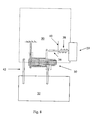
- Figures 6 and 7 illustrate different manners of actually loosening the spring 16.
- the wedge 15 is illustrated together with two different positions of the end 20 of the spring 16. Depending on the distance between the wedge 15 and the helical part of the spring 16, this movement of the end 20 will provide more or less loosening of the spring 16.
- the wedge 15 is supplemented by another element 15' forming, together with the wedge 15 a track in which the end 20 travels.
- This track may be used for actually biasing the end 20 in the tightening direction.
- This operation is seen as the un-biased position of the end 20 is illustrated by a dotted end 20'.
- the end 20 is that depicted at the lower position, which is lower than the unbiased position 20'.
- FIG. 7 Another manner is seen in Figure 7 , where the end 20 rests against a flexible element 24 inside which an elongated, stiff element 26 may slide. It is seen that the end 20, in fact, is biased against the element 24 in such a manner that when the element 26 is retracted, the end 20 will deform the element 24 and thereby tighten the spring 16.
- the element 26 is biased away from and out of the element 24 by a biasing spring 27, and the elements 26, 24 and 20 are controlled by holding means 22.
- loosening of the spring 16 may be performed by moving the spring end 20 in a number of ways, such as in the direction of the fat arrow or in a direction along the end 20 toward the spring 16.
- Figure 8 illustrates a two-part system having a first part 30 connected via a hinge 50 to a second part 32.
- the reference numerals from Figure 5 have been omitted in order to retain the clarity of the figure.
- the part 30 of the system of Figure 8 has a spring loosening mechanism having a push button 29 connected to a loosening mechanism 36, such as the wedge 15, and being biased by a biasing spring 38 engaging a fixed element 40 in the part 30.
- the first part 30 is further rotationally attached to the second part 32 by an element 42. This is only to stabilize the rotation of the parts.
- the mobile telephone 28 has the first and second parts 30 and 32 as well as a hinge or clutch illustrated at 33, a release mechanism 34 for the hinge 33.
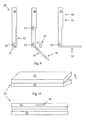
- Figure 9 illustrates three different angles between the first part 30 and the second part 32 and therefore a specific use of the mobile telephone 28.
- the mobile telephone 28 will be stored as illustrated in the left-most drawing where the first and second parts 30 and 32 are adjacent to each other.
- the second part 32 has a microphone 36 protected in the position in the left-most illustration.
- the telephone 28 also has a speaker 39 in the first part 30.
- the hinge 33 is provided in the telephone 28 so that the rod member 14 is attached to the second part 32 and so that the rod member 12 and/or the end 18 is attached to the first part 30. Also, a release mechanism as that illustrated by the wedge 15 is operatively connected to the button 34. The spring 16 is directed so that the rotation in the direction of the fat arrow (see Figs. 2 or 3 ) will take place when rotating the second part 32 as illustrated by the fat arrow in the middle illustration of Figure 9 .
- the second part 32 is rotated as illustrated by the fat arrow in the middle illustration. In this manner, the microphone becomes accessible. This activation is obtained by releasing the release mechanism 34, which loosens the spring 16 and allows the biasing means to overcome the third friction and rotate the second part 32 to e.g. a stopping position as that illustrated in the middle illustration.
- This position may be pre-defined as that providing the optimal position for use when making a telephone call. This position may also be one where the second part 32 is rotated further in the direction of the fat arrow.
- the release button 34 is disengaged.
- the second part 32 may be rotated in a direction opposite to that illustrated by the fat arrow. Due to the friction of the hinge 33 - as well as the operation of the biasing means, the second part 32 will be substantially fixed and will be able to e.g. hold the telephone at the desired angle or in the desired position.
- the telephone 28 may also have a locking means 37 for maintaining the second part 32 in the closed position even if the release button 34 is operated.
- the hinge may be reversed to that a snap closing is achieved by operating the button 34.
- the parts are rotated by hand (in the low friction direction of the hinge), and are maintained in that angular position until the button is operated, where after the biasing spring will close the parts again.
- FIG. 10 a further embodiment is seen at an angle from the back (above) and directly from the front (below).
- This embodiment 50 may also be a telephone or a palm computer having two parts 52 and 54 interconnected by a hinge (not illustrated) and having a release button 56 to be used as described above.
- operation of the release button 56 may make the biasing means open the telephone/computer 50 for operation. Releasing the release button will make further rotation in the opening direction (the fat arrow) difficult (due to the high friction), but rotation in the opposite direction (the closing direction) will be easy.
- any desired angle between the parts may be obtained at the same time as a snap opening (the operation of the biasing means) may be obtained.
- the present embodiments have centred on mobile telephones.
- the same functionality may be obtained in any type of element where a combination of an automatic opening of a device is desired combined with a subsequent, freely selected positioning of the elements.
- This may be in hand-held or palm-size electronic systems, portable computers or toys of any type.
Landscapes
- Engineering & Computer Science (AREA)
- Computer Hardware Design (AREA)
- Theoretical Computer Science (AREA)
- Physics & Mathematics (AREA)
- Human Computer Interaction (AREA)
- General Engineering & Computer Science (AREA)
- General Physics & Mathematics (AREA)
- Signal Processing (AREA)
- Mathematical Physics (AREA)
- Computer Networks & Wireless Communication (AREA)
- Mechanical Engineering (AREA)
- Telephone Set Structure (AREA)
- Pivots And Pivotal Connections (AREA)
Claims (16)
- Gelenk (10, 33, 50) zum Unterstützen der Drehbewegung eines ersten Gelenkteils (12, 30) relativ zu einem zweiten Gelenkteil (14, 32) und um eine Drehachse des Gelenks (10, 33, 50), wobei das Gelenk (10, 33, 50) Folgendes umfasst:- eine Schraubenfeder (16) mit einer Längsachse entlang der Drehachse, wobei die Feder (16) einen oder mehrere gewickelte Drähte aus einem Material umfasst und jeder Draht zwei Enden (18, 20) sowie einen Teil hat, der sich außerhalb der Schraubenfeder erstreckt,- wobei der erste Gelenkteil (12, 30) sich in die Schraubenfeder (16) hinein erstreckt und einen inneren Teil (17) der Schraubenfeder (16) in einer ersten Position oder einem ersten Bereich entlang der Längsachse berührt, und- wobei der zweite Gelenkteil (14, 32) an den sich erstreckenden Teilen jedes der ein oder mehreren Drähte der Schraubenfeder (16) befestigt ist,wobei die Feder (16) es unterstützt, dass:- eine Drehung des ersten Gelenkteils (12, 30) in einer ersten Richtung um die Längsachse und relativ zum zweiten Gelenkteil (14, 32) eine erste, niedrigere Reibungskraft zwischen dem ersten Gelenkteil (12, 30) und der Schraubenfeder bereitstellt, und- eine Drehung des ersten Gelenkteils (12, 30) in einer zweiten Richtung, die entgegengesetzt zur ersten Richtung ist, um die Längsachse und relativ zum zweiten Gelenkteil (14, 32) eine zweite, höhere Reibungskraft zwischen dem ersten Gelenkteil (12, 30) und der Schraubenfeder bereitstellt,dadurch gekennzeichnet, dass das Gelenk außerdem Folgendes umfasst:ein Freigabemittel (15, 34, 56) zum Erhöhen eines Durchmessers der Schraubenfeder (16) an der ersten Position oder dem ersten Bereich, um die zweite, höhere Reibungskraft zwischen dem ersten Gelenkteil (12, 30) und der Schraubenfeder (16) zu verringern, und dies während einer Drehung des ersten Gelenkteils (12, 30) in der zweiten Richtung, wobei die zweite, höhere Reibungskraft auf eine dritte Reibungskraft verringert wird, undein Vorspannmittel (27, 38, 44) zum Bereitstellen einer Drehung des ersten Gelenkteils (12, 30) in der zweiten Richtung, wenn das Freigabemittel (15, 34, 56) betätigt wird, wobei das Vorspannmittel (27, 38, 44) eine Kraft bereitstellt, die eine Kraft übersteigt, die notwendig ist, um die dritte Reibungskraft zu überwinden, die jedoch kleiner ist als eine Kraft, die notwendig ist, um die zweite Reibungskraft zu überwinden.
- Gelenk nach Anspruch 1, wobei das Freigabemittel (15, 34, 56) für jedes Gelenk ein keilförmiges Element (15) umfasst, das dafür eingerichtet ist, verschoben zu werden und das oder die Enden zu versetzen.
- Gelenk nach Anspruch 1, wobei das Freigabemittel (15, 34, 56) für jedes Gelenk ein biegsames Element umfasst, das mit dem oder den Ende(n) ineinander greift, wobei das oder die Ende(n) dafür eingerichtet sind, das biegsame Element in einen ersten, verformten Zustand vorzuspannen, wenn es oder sie in einer ersten Position sind, und das Freigabemittel (15, 34, 56) ein Mittel umfasst, um das biegsame Element in einen ersten, normalen Zustand zu bringen und dabei das oder die Ende(n) in eine zweite Position zu bringen.
- Gelenk nach Anspruch 3, wobei das biegsame Element hohl ist und wobei das Mittel zum Bringen ein Mittel umfasst, dafür eingerichtet ist, in den Hohlraum des biegsamen Elements verschoben zu werden.
- Gelenk nach Anspruch 3 oder 4, wobei das Mittel zum Bringen dafür eingerichtet ist, in das biegsame Element hinein und aus ihm heraus verschoben zu werden, und es in eine Richtung aus dem Hohlraum heraus vorgespannt ist.
- Mobiles Endgerät mit zwei Teilen, die untereinander durch ein Gelenk nach einem der Ansprüche 1 bis 5 verbunden sind.
- Mobiles Endgerät nach Anspruch 6, wobei der zweite Gelenkteil sich in die Schraubenfeder hinein erstreckt und dabei den inneren Teil der Schraubenfeder in einer zweiten Position oder einem zweiten Bereich entlang der Längsachse berührt.
- Mobiles Endgerät nach Anspruch 6, wobei die Feder an einem Ende jedes der ein oder mehreren Drähte einen nicht-schraubenförmigen Teil umfasst und wobei der zweite Gelenkteil den nicht-schraubenförmigen Teil berührt.
- Mobiles Endgerät nach einem der Ansprüche 6 bis 8, wobei ein Ende jedes der Drähte/des Drahts der Feder relativ zum zweiten Gelenkteil feststehend ist und wobei das Freigabemittel (15, 34, 56) dafür eingerichtet ist, das oder die anderen Ende(n) des Drahts oder der Drähte von der ersten Position in die zweite Position zu versetzen.
- Mobiles Endgerät nach Anspruch 9, wobei das Freigabemittel (15, 34, 56) dafür eingerichtet ist, relativ zum zweiten Gelenkteil nicht gedreht zu werden.
- Mobiles Endgerät nach einem der Ansprüche 6 bis 10, das außerdem ein Feststellmittel umfasst, um die Teile in einem vorgegebenen Drehwinkel zu halten, und dies selbst dann, wenn das Freigabemittel (15, 34, 56) betätigt wird.
- Mobiles Endgerät nach einem der Ansprüche 6 bis 11, wobei das Freigabemittel (15, 34, 56) für jedes Gelenk ein keilförmiges Element umfasst, das dafür eingerichtet ist, verschoben zu werden und das oder die Ende(n) zu versetzen.
- Mobiles Endgerät nach einem der Ansprüche 6 bis 12, wobei das Freigabemittel (15, 34, 56) für jedes Gelenk ein biegsames Element umfasst, das mit dem oder den Ende(n) ineinander greift, wobei das oder die Ende(n) dafür eingerichtet sind, das biegsame Element in einen ersten, verformten Zustand vorzuspannen, wenn es oder sie in der ersten Position sind, und das Freigabemittel (15, 34, 56) ein Mittel umfasst, um das biegsame Element in einen ersten, normalen Zustand zu bringen und dabei das oder die Ende(n) in eine zweite Position zu bringen.
- Mobiles Endgerät nach Anspruch 13, wobei das biegsame Element hohl ist und wobei das Mittel zum Bringen ein Mittel umfasst, dafür eingerichtet ist, in den Hohlraum des biegsamen Elements verschoben zu werden.
- Mobiles Endgerät nach einem der Ansprüche 13 bis 14, wobei das Mittel zum Bringen dafür eingerichtet ist, in das biegsame Element hinein und aus ihm heraus verschoben zu werden, und es in eine Richtung aus dem Hohlraum heraus vorgespannt ist.
- Verfahren zum Bedienen eines mobilen Endgeräts nach einem der Ansprüche 6 bis 15, wobei das Verfahren Folgendes umfasst:- Betätigen des Freigabemittels (15, 34, 56), um hierdurch das Vorspannmittel (27, 38, 44) den ersten Gelenkteil in der zweiten Richtung und relativ zum zweiten Gelenkmittel von einer Anfangsposition über einen ersten Winkel in eine zweite Position drehen zu lassen,- Freigeben des Freigabemittels (15, 34, 56),- Drehen des ersten Gelenkteils in der zweiten Richtung und über einen zweiten Winkel, der kleiner ist als der erste Winkel, in eine dritte Position, und- Gestatten, dass das Gelenk den ersten Gelenkteil in der dritten Position behält.
Applications Claiming Priority (3)
| Application Number | Priority Date | Filing Date | Title |
|---|---|---|---|
| US323823 | 2002-12-20 | ||
| US10/323,823 US7079874B2 (en) | 2002-12-20 | 2002-12-20 | Transformer hinge design |
| PCT/DK2003/000880 WO2004057139A1 (en) | 2002-12-20 | 2003-12-15 | A mobile terminal with a hinge, a method of operating the mobile terminal and a hinge |
Publications (2)
| Publication Number | Publication Date |
|---|---|
| EP1573159A1 EP1573159A1 (de) | 2005-09-14 |
| EP1573159B1 true EP1573159B1 (de) | 2013-03-20 |
Family
ID=32680719
Family Applications (1)
| Application Number | Title | Priority Date | Filing Date |
|---|---|---|---|
| EP03779738A Expired - Lifetime EP1573159B1 (de) | 2002-12-20 | 2003-12-15 | Mobiles endgerät mit einem scharnier, verfahren zum betrieb des mobilen endgerätes und scharnier |
Country Status (6)
| Country | Link |
|---|---|
| US (2) | US7079874B2 (de) |
| EP (1) | EP1573159B1 (de) |
| KR (1) | KR100807158B1 (de) |
| CN (1) | CN1754035B (de) |
| AU (1) | AU2003287898A1 (de) |
| WO (1) | WO2004057139A1 (de) |
Families Citing this family (18)
| Publication number | Priority date | Publication date | Assignee | Title |
|---|---|---|---|---|
| US20040253999A1 (en) * | 2003-06-16 | 2004-12-16 | Sergio Castaneda | Attachability enhanced wireless phone |
| KR100678265B1 (ko) * | 2005-01-11 | 2007-02-02 | 삼성전자주식회사 | 휴대 단말기의 반 자동 스윙 장치 |
| DE112007000731B4 (de) * | 2006-03-27 | 2024-02-08 | Southco, Inc. | Anzeige-Befestigungsvorrichtung |
| TWI364647B (en) * | 2007-07-13 | 2012-05-21 | Asustek Comp Inc | Overturning cover mechanism and electronic device using the same |
| EP2187118A1 (de) * | 2008-11-13 | 2010-05-19 | Derungs Licht AG | Gelenkarm mit Drehgelenk |
| US9277812B2 (en) | 2010-07-08 | 2016-03-08 | Southco, Inc. | Display support with first and second arms and mechanism for maintaining constant orientation of the plane bisecting the range of rotation of the second arm relative to a support base |
| US9483084B2 (en) * | 2013-09-27 | 2016-11-01 | Intel Corporation | Frictional hinge for electronic devices |
| EP2910720A1 (de) * | 2014-02-18 | 2015-08-26 | Gealan Formteile GmbH | Variabler betriebsmechanismus |
| US9447620B2 (en) | 2014-09-30 | 2016-09-20 | Microsoft Technology Licensing, Llc | Hinge mechanism with multiple preset positions |
| US9600034B2 (en) * | 2015-02-13 | 2017-03-21 | Google Inc. | Attaching computing device to mount by magnets |
| US9752361B2 (en) | 2015-06-18 | 2017-09-05 | Microsoft Technology Licensing, Llc | Multistage hinge |
| US9864415B2 (en) | 2015-06-30 | 2018-01-09 | Microsoft Technology Licensing, Llc | Multistage friction hinge |
| EP3875829A3 (de) | 2016-03-07 | 2021-10-13 | Southco, Inc. | Stützarmbaugruppe für eine anzeige zur montage einer anzeige |
| US10344797B2 (en) | 2016-04-05 | 2019-07-09 | Microsoft Technology Licensing, Llc | Hinge with multiple preset positions |
| US10037057B2 (en) | 2016-09-22 | 2018-07-31 | Microsoft Technology Licensing, Llc | Friction hinge |
| WO2019141883A1 (es) * | 2018-01-19 | 2019-07-25 | Rodriguez Abesamis Alejandro | Dispositivo de protección para teléfono móvil con apertura automática |
| USD964337S1 (en) | 2019-01-22 | 2022-09-20 | Alejandro Rodriguez Abesamis | Protection device for a mobile telephone with automatic opening |
| JP7698283B2 (ja) * | 2021-03-22 | 2025-06-25 | 株式会社ナチュラレーザ・ワン | 開閉装置並びにこの開閉装置を用いた端末機器 |
Family Cites Families (34)
| Publication number | Priority date | Publication date | Assignee | Title |
|---|---|---|---|---|
| JPH0640311Y2 (ja) | 1988-12-21 | 1994-10-19 | 日本発条株式会社 | 軸ロック装置 |
| JPH06508408A (ja) * | 1992-03-11 | 1994-09-22 | モトローラ・インコーポレーテッド | ヒンジ機構 |
| US5784759A (en) * | 1993-11-02 | 1998-07-28 | King; David Russell | Hinge construction |
| US5564163A (en) * | 1994-11-08 | 1996-10-15 | Cema Technologies, Inc. | Lockable hinge assembly |
| WO1996017463A1 (en) * | 1994-11-28 | 1996-06-06 | Ericsson Inc. | Portable telephone with an asymmetric hinged housing configuration |
| JP3737160B2 (ja) * | 1995-03-31 | 2006-01-18 | 富士通株式会社 | 折り畳み携帯電話機用ヒンジ機構及び折り畳み携帯電話機 |
| US5649309A (en) * | 1995-05-18 | 1997-07-15 | Motorola, Inc. | Wireless communication device having an axially aligned cover release mechanism |
| US5525667A (en) * | 1995-08-02 | 1996-06-11 | Tenneco Plastics, Inc. | Polymer orientation |
| US5697125A (en) * | 1995-11-27 | 1997-12-16 | Reell Precision Manufacturing Corporation | Clip friction hinge |
| US5813093A (en) * | 1997-01-31 | 1998-09-29 | Lucent Technologies Inc. | Hinge assembly |
| US6256481B1 (en) * | 1997-04-26 | 2001-07-03 | Samsung Electronics Co., Ltd. | Microphone connecting device for flip type portable telephone |
| CN1261498A (zh) * | 1997-05-21 | 2000-07-26 | E·S·P·通讯股份有限公司 | 呼叫者产生记费的“仅由呼叫者”启动的双向无线通信的系统、方法和装置 |
| JP3732619B2 (ja) * | 1997-06-16 | 2006-01-05 | 加藤電機株式会社 | ヒンジ装置 |
| TW411069U (en) * | 1997-10-08 | 2000-11-01 | Kato Electric & Machinary Co | Hinge device |
| US5996178A (en) * | 1997-10-15 | 1999-12-07 | Motorola, Inc. | Hinge suitable for use in a foldable device |
| US5987122A (en) * | 1998-01-08 | 1999-11-16 | Qualcomm Incorporated | Portable phone with cover actuating hinge assembly |
| US6157717A (en) * | 1998-03-19 | 2000-12-05 | Qualcomm Incorporated | Snap hinge mechanism for flip style portable phone |
| US6148079A (en) * | 1998-03-19 | 2000-11-14 | Qualcomm Incorporated | Hinge apparatus for flip style portable phone |
| US6122801A (en) * | 1998-05-28 | 2000-09-26 | Telefonaktiebolaget Lm Ericsson | Hinge mechanism |
| US6104621A (en) * | 1998-06-30 | 2000-08-15 | Ericsson, Inc. | Torsional hinging mechanism |
| SE516906C2 (sv) * | 1999-03-23 | 2002-03-19 | Ericsson Telefon Ab L M | Anordning vid en mobiltelefon innefattande en svängbart skyddande lucka, som när den öppnas intar ett förutbestämt öppet läge |
| JP2000278373A (ja) * | 1999-03-29 | 2000-10-06 | Ricoh Co Ltd | 携帯型電子機器 |
| JP2001103568A (ja) * | 1999-09-30 | 2001-04-13 | Toshiba Corp | 通信システム、この通信システムに用いられる移動体通信装置、携帯型情報処理装置及びデータ通信方法 |
| US6296215B1 (en) * | 1999-12-15 | 2001-10-02 | Group Dekko Services, Llc | Adjustable keyboard support |
| JP4637332B2 (ja) * | 2000-08-04 | 2011-02-23 | パナソニック株式会社 | 折り畳み式携帯無線装置 |
| US6678539B1 (en) * | 2001-01-22 | 2004-01-13 | Lu Sheng-Nan | Mobile phone cover hinge |
| WO2002068833A1 (en) * | 2001-02-26 | 2002-09-06 | Sugatsune Kogyo Co., Ltd. | Hinge device |
| US6766180B2 (en) * | 2001-03-01 | 2004-07-20 | Qualcomm, Incorporated | Preferential deflection hinge mechanism with an idler for foldable portable electronic devices |
| JP2003120653A (ja) * | 2001-10-17 | 2003-04-23 | Ohashi Technica Inc | ヒンジ装置及びそれを用いた携帯電話機 |
| TW576080B (en) * | 2002-03-01 | 2004-02-11 | Benq Corp | Hinge device |
| TW577213B (en) * | 2002-03-14 | 2004-02-21 | Benq Corp | Flipper phone having a hinge mechanism with auto-lock function |
| KR100469361B1 (ko) * | 2002-07-24 | 2005-01-31 | 삼성전기주식회사 | 휴대전화기의 폴더 구동장치 |
| US7529571B2 (en) * | 2003-09-03 | 2009-05-05 | Samsung Electronics Co., Ltd. | Sliding/hinge apparatus for sliding/rotating type mobile terminals |
| KR100557078B1 (ko) * | 2003-11-06 | 2006-03-03 | 삼성전자주식회사 | 디스플레이 회전형 휴대 단말기의 힌지 장치 |
-
2002
- 2002-12-20 US US10/323,823 patent/US7079874B2/en not_active Expired - Fee Related
-
2003
- 2003-12-15 EP EP03779738A patent/EP1573159B1/de not_active Expired - Lifetime
- 2003-12-15 KR KR1020057011488A patent/KR100807158B1/ko not_active Expired - Fee Related
- 2003-12-15 US US10/539,168 patent/US20060188092A1/en not_active Abandoned
- 2003-12-15 AU AU2003287898A patent/AU2003287898A1/en not_active Abandoned
- 2003-12-15 WO PCT/DK2003/000880 patent/WO2004057139A1/en not_active Ceased
- 2003-12-15 CN CN2003801098524A patent/CN1754035B/zh not_active Expired - Fee Related
Also Published As
| Publication number | Publication date |
|---|---|
| US20040198412A1 (en) | 2004-10-07 |
| AU2003287898A1 (en) | 2004-07-14 |
| EP1573159A1 (de) | 2005-09-14 |
| KR100807158B1 (ko) | 2008-02-27 |
| CN1754035B (zh) | 2011-09-07 |
| HK1087751A1 (en) | 2006-10-20 |
| KR20050084432A (ko) | 2005-08-26 |
| US7079874B2 (en) | 2006-07-18 |
| WO2004057139A1 (en) | 2004-07-08 |
| US20060188092A1 (en) | 2006-08-24 |
| CN1754035A (zh) | 2006-03-29 |
Similar Documents
| Publication | Publication Date | Title |
|---|---|---|
| EP1573159B1 (de) | Mobiles endgerät mit einem scharnier, verfahren zum betrieb des mobilen endgerätes und scharnier | |
| US20030116596A1 (en) | Wearable electronic device | |
| JP3183342B2 (ja) | ヒンジ構造 | |
| US7832056B2 (en) | Opening-closing device | |
| JP5007236B2 (ja) | 開閉装置及びこれを用いた携帯機器 | |
| EP1213640A2 (de) | Vorrichtung zum Öffnen eines elektronischen Handgeräts | |
| JPWO2002077472A1 (ja) | ロータリーアクチュエータを備えたヒンジ構造 | |
| JP4205367B2 (ja) | 電子機器 | |
| JP2007267238A (ja) | 携帯機器 | |
| US20010036265A1 (en) | Automatic opening and closing apparatus for mobile phones | |
| JP4383307B2 (ja) | ヒンジ装置 | |
| JP2001251396A (ja) | 折り畳み式携帯電話機 | |
| US7353048B2 (en) | Transformer hinge design | |
| JP2001251399A (ja) | 折り畳み式携帯電話機 | |
| JP2011511915A (ja) | 無線通信装置用のヒンジ機構 | |
| JP4546888B2 (ja) | ヒンジ装置並びにヒンジ装置を用いた電子機器 | |
| JP3145663B2 (ja) | ヒンジ装置 | |
| JP2002303316A (ja) | ヒンジ装置並びにヒンジ装置を用いた携帯式電子機器 | |
| JP2001173635A (ja) | ヒンジ装置 | |
| JP3656041B2 (ja) | ヒンジ装置並びにヒンジ装置を用いた電子機器 | |
| HK1087751B (en) | A mobile terminal with a hinge, a method of operating the mobile terminal and a hinge | |
| CA2278414C (en) | Bi-stable spring loaded pivoting joint | |
| JP2003247530A (ja) | 情報処理装置 | |
| JP2001057501A (ja) | アンテナ伸縮操作装置 | |
| KR101013770B1 (ko) | 접이식 휴대단말기용 댐핑 힌지 |
Legal Events
| Date | Code | Title | Description |
|---|---|---|---|
| PUAI | Public reference made under article 153(3) epc to a published international application that has entered the european phase |
Free format text: ORIGINAL CODE: 0009012 |
|
| 17P | Request for examination filed |
Effective date: 20050613 |
|
| AK | Designated contracting states |
Kind code of ref document: A1 Designated state(s): AT BE BG CH CY CZ DE DK EE ES FI FR GB GR HU IE IT LI LU MC NL PT RO SE SI SK |
|
| AX | Request for extension of the european patent |
Extension state: AL LT LV MK |
|
| DAX | Request for extension of the european patent (deleted) | ||
| RIN1 | Information on inventor provided before grant (corrected) |
Inventor name: BARNETT, RICKY Inventor name: FERRANTI, GIOVANNI Inventor name: PONTOPPIDAN, MORTEN |
|
| 17Q | First examination report despatched |
Effective date: 20120208 |
|
| GRAP | Despatch of communication of intention to grant a patent |
Free format text: ORIGINAL CODE: EPIDOSNIGR1 |
|
| GRAS | Grant fee paid |
Free format text: ORIGINAL CODE: EPIDOSNIGR3 |
|
| GRAA | (expected) grant |
Free format text: ORIGINAL CODE: 0009210 |
|
| AK | Designated contracting states |
Kind code of ref document: B1 Designated state(s): AT BE BG CH CY CZ DE DK EE ES FI FR GB GR HU IE IT LI LU MC NL PT RO SE SI SK |
|
| REG | Reference to a national code |
Ref country code: GB Ref legal event code: FG4D |
|
| REG | Reference to a national code |
Ref country code: CH Ref legal event code: EP |
|
| REG | Reference to a national code |
Ref country code: IE Ref legal event code: FG4D |
|
| REG | Reference to a national code |
Ref country code: AT Ref legal event code: REF Ref document number: 602203 Country of ref document: AT Kind code of ref document: T Effective date: 20130415 |
|
| REG | Reference to a national code |
Ref country code: DE Ref legal event code: R096 Ref document number: 60343565 Country of ref document: DE Effective date: 20130516 |
|
| PG25 | Lapsed in a contracting state [announced via postgrant information from national office to epo] |
Ref country code: BG Free format text: LAPSE BECAUSE OF FAILURE TO SUBMIT A TRANSLATION OF THE DESCRIPTION OR TO PAY THE FEE WITHIN THE PRESCRIBED TIME-LIMIT Effective date: 20130620 Ref country code: ES Free format text: LAPSE BECAUSE OF FAILURE TO SUBMIT A TRANSLATION OF THE DESCRIPTION OR TO PAY THE FEE WITHIN THE PRESCRIBED TIME-LIMIT Effective date: 20130701 Ref country code: SE Free format text: LAPSE BECAUSE OF FAILURE TO SUBMIT A TRANSLATION OF THE DESCRIPTION OR TO PAY THE FEE WITHIN THE PRESCRIBED TIME-LIMIT Effective date: 20130320 |
|
| REG | Reference to a national code |
Ref country code: AT Ref legal event code: MK05 Ref document number: 602203 Country of ref document: AT Kind code of ref document: T Effective date: 20130320 |
|
| PG25 | Lapsed in a contracting state [announced via postgrant information from national office to epo] |
Ref country code: GR Free format text: LAPSE BECAUSE OF FAILURE TO SUBMIT A TRANSLATION OF THE DESCRIPTION OR TO PAY THE FEE WITHIN THE PRESCRIBED TIME-LIMIT Effective date: 20130621 Ref country code: FI Free format text: LAPSE BECAUSE OF FAILURE TO SUBMIT A TRANSLATION OF THE DESCRIPTION OR TO PAY THE FEE WITHIN THE PRESCRIBED TIME-LIMIT Effective date: 20130320 Ref country code: SI Free format text: LAPSE BECAUSE OF FAILURE TO SUBMIT A TRANSLATION OF THE DESCRIPTION OR TO PAY THE FEE WITHIN THE PRESCRIBED TIME-LIMIT Effective date: 20130320 |
|
| REG | Reference to a national code |
Ref country code: NL Ref legal event code: VDEP Effective date: 20130320 |
|
| PG25 | Lapsed in a contracting state [announced via postgrant information from national office to epo] |
Ref country code: BE Free format text: LAPSE BECAUSE OF FAILURE TO SUBMIT A TRANSLATION OF THE DESCRIPTION OR TO PAY THE FEE WITHIN THE PRESCRIBED TIME-LIMIT Effective date: 20130320 |
|
| PG25 | Lapsed in a contracting state [announced via postgrant information from national office to epo] |
Ref country code: EE Free format text: LAPSE BECAUSE OF FAILURE TO SUBMIT A TRANSLATION OF THE DESCRIPTION OR TO PAY THE FEE WITHIN THE PRESCRIBED TIME-LIMIT Effective date: 20130320 Ref country code: AT Free format text: LAPSE BECAUSE OF FAILURE TO SUBMIT A TRANSLATION OF THE DESCRIPTION OR TO PAY THE FEE WITHIN THE PRESCRIBED TIME-LIMIT Effective date: 20130320 Ref country code: PT Free format text: LAPSE BECAUSE OF FAILURE TO SUBMIT A TRANSLATION OF THE DESCRIPTION OR TO PAY THE FEE WITHIN THE PRESCRIBED TIME-LIMIT Effective date: 20130722 Ref country code: NL Free format text: LAPSE BECAUSE OF FAILURE TO SUBMIT A TRANSLATION OF THE DESCRIPTION OR TO PAY THE FEE WITHIN THE PRESCRIBED TIME-LIMIT Effective date: 20130320 Ref country code: RO Free format text: LAPSE BECAUSE OF FAILURE TO SUBMIT A TRANSLATION OF THE DESCRIPTION OR TO PAY THE FEE WITHIN THE PRESCRIBED TIME-LIMIT Effective date: 20130320 Ref country code: SK Free format text: LAPSE BECAUSE OF FAILURE TO SUBMIT A TRANSLATION OF THE DESCRIPTION OR TO PAY THE FEE WITHIN THE PRESCRIBED TIME-LIMIT Effective date: 20130320 Ref country code: CZ Free format text: LAPSE BECAUSE OF FAILURE TO SUBMIT A TRANSLATION OF THE DESCRIPTION OR TO PAY THE FEE WITHIN THE PRESCRIBED TIME-LIMIT Effective date: 20130320 |
|
| PG25 | Lapsed in a contracting state [announced via postgrant information from national office to epo] |
Ref country code: CY Free format text: LAPSE BECAUSE OF FAILURE TO SUBMIT A TRANSLATION OF THE DESCRIPTION OR TO PAY THE FEE WITHIN THE PRESCRIBED TIME-LIMIT Effective date: 20130320 |
|
| PLBE | No opposition filed within time limit |
Free format text: ORIGINAL CODE: 0009261 |
|
| STAA | Information on the status of an ep patent application or granted ep patent |
Free format text: STATUS: NO OPPOSITION FILED WITHIN TIME LIMIT |
|
| PG25 | Lapsed in a contracting state [announced via postgrant information from national office to epo] |
Ref country code: DK Free format text: LAPSE BECAUSE OF FAILURE TO SUBMIT A TRANSLATION OF THE DESCRIPTION OR TO PAY THE FEE WITHIN THE PRESCRIBED TIME-LIMIT Effective date: 20130320 |
|
| 26N | No opposition filed |
Effective date: 20140102 |
|
| PG25 | Lapsed in a contracting state [announced via postgrant information from national office to epo] |
Ref country code: IT Free format text: LAPSE BECAUSE OF FAILURE TO SUBMIT A TRANSLATION OF THE DESCRIPTION OR TO PAY THE FEE WITHIN THE PRESCRIBED TIME-LIMIT Effective date: 20130320 |
|
| REG | Reference to a national code |
Ref country code: DE Ref legal event code: R097 Ref document number: 60343565 Country of ref document: DE Effective date: 20140102 |
|
| REG | Reference to a national code |
Ref country code: DE Ref legal event code: R119 Ref document number: 60343565 Country of ref document: DE |
|
| REG | Reference to a national code |
Ref country code: CH Ref legal event code: PL |
|
| GBPC | Gb: european patent ceased through non-payment of renewal fee |
Effective date: 20131215 |
|
| PG25 | Lapsed in a contracting state [announced via postgrant information from national office to epo] |
Ref country code: LU Free format text: LAPSE BECAUSE OF FAILURE TO SUBMIT A TRANSLATION OF THE DESCRIPTION OR TO PAY THE FEE WITHIN THE PRESCRIBED TIME-LIMIT Effective date: 20131215 Ref country code: MC Free format text: LAPSE BECAUSE OF FAILURE TO SUBMIT A TRANSLATION OF THE DESCRIPTION OR TO PAY THE FEE WITHIN THE PRESCRIBED TIME-LIMIT Effective date: 20130320 |
|
| REG | Reference to a national code |
Ref country code: IE Ref legal event code: MM4A |
|
| REG | Reference to a national code |
Ref country code: FR Ref legal event code: ST Effective date: 20140829 |
|
| REG | Reference to a national code |
Ref country code: DE Ref legal event code: R119 Ref document number: 60343565 Country of ref document: DE Effective date: 20140701 |
|
| PG25 | Lapsed in a contracting state [announced via postgrant information from national office to epo] |
Ref country code: DE Free format text: LAPSE BECAUSE OF NON-PAYMENT OF DUE FEES Effective date: 20140701 Ref country code: LI Free format text: LAPSE BECAUSE OF NON-PAYMENT OF DUE FEES Effective date: 20131231 Ref country code: CH Free format text: LAPSE BECAUSE OF NON-PAYMENT OF DUE FEES Effective date: 20131231 Ref country code: IE Free format text: LAPSE BECAUSE OF NON-PAYMENT OF DUE FEES Effective date: 20131215 |
|
| PG25 | Lapsed in a contracting state [announced via postgrant information from national office to epo] |
Ref country code: GB Free format text: LAPSE BECAUSE OF NON-PAYMENT OF DUE FEES Effective date: 20131215 Ref country code: FR Free format text: LAPSE BECAUSE OF NON-PAYMENT OF DUE FEES Effective date: 20131231 |
|
| PG25 | Lapsed in a contracting state [announced via postgrant information from national office to epo] |
Ref country code: HU Free format text: LAPSE BECAUSE OF FAILURE TO SUBMIT A TRANSLATION OF THE DESCRIPTION OR TO PAY THE FEE WITHIN THE PRESCRIBED TIME-LIMIT; INVALID AB INITIO Effective date: 20031215 |