EP1573159B1 - A mobile terminal with a hinge, a method of operating the mobile terminal and a hinge - Google Patents
A mobile terminal with a hinge, a method of operating the mobile terminal and a hinge Download PDFInfo
- Publication number
- EP1573159B1 EP1573159B1 EP03779738A EP03779738A EP1573159B1 EP 1573159 B1 EP1573159 B1 EP 1573159B1 EP 03779738 A EP03779738 A EP 03779738A EP 03779738 A EP03779738 A EP 03779738A EP 1573159 B1 EP1573159 B1 EP 1573159B1
- Authority
- EP
- European Patent Office
- Prior art keywords
- hinge
- spring
- hinge part
- mobile terminal
- flexible element
- Prior art date
- Legal status (The legal status is an assumption and is not a legal conclusion. Google has not performed a legal analysis and makes no representation as to the accuracy of the status listed.)
- Expired - Lifetime
Links
Images

Classifications
-
- H—ELECTRICITY
- H04—ELECTRIC COMMUNICATION TECHNIQUE
- H04M—TELEPHONIC COMMUNICATION
- H04M1/00—Substation equipment, e.g. for use by subscribers
- H04M1/02—Constructional features of telephone sets
- H04M1/0202—Portable telephone sets, e.g. cordless phones, mobile phones or bar type handsets
- H04M1/0206—Portable telephones comprising a plurality of mechanically joined movable body parts, e.g. hinged housings
- H04M1/0208—Portable telephones comprising a plurality of mechanically joined movable body parts, e.g. hinged housings characterized by the relative motions of the body parts
- H04M1/0214—Foldable telephones, i.e. with body parts pivoting to an open position around an axis parallel to the plane they define in closed position
- H04M1/0216—Foldable in one direction, i.e. using a one degree of freedom hinge
-
- H—ELECTRICITY
- H04—ELECTRIC COMMUNICATION TECHNIQUE
- H04B—TRANSMISSION
- H04B1/00—Details of transmission systems, not covered by a single one of groups H04B3/00 - H04B13/00; Details of transmission systems not characterised by the medium used for transmission
- H04B1/38—Transceivers, i.e. devices in which transmitter and receiver form a structural unit and in which at least one part is used for functions of transmitting and receiving
-
- E—FIXED CONSTRUCTIONS
- E05—LOCKS; KEYS; WINDOW OR DOOR FITTINGS; SAFES
- E05D—HINGES OR SUSPENSION DEVICES FOR DOORS, WINDOWS OR WINGS
- E05D11/00—Additional features or accessories of hinges
- E05D11/08—Friction devices between relatively-movable hinge parts
-
- G—PHYSICS
- G06—COMPUTING OR CALCULATING; COUNTING
- G06F—ELECTRIC DIGITAL DATA PROCESSING
- G06F1/00—Details not covered by groups G06F3/00 - G06F13/00 and G06F21/00
- G06F1/16—Constructional details or arrangements
- G06F1/1613—Constructional details or arrangements for portable computers
- G06F1/1615—Constructional details or arrangements for portable computers with several enclosures having relative motions, each enclosure supporting at least one I/O or computing function
- G06F1/1616—Constructional details or arrangements for portable computers with several enclosures having relative motions, each enclosure supporting at least one I/O or computing function with folding flat displays, e.g. laptop computers or notebooks having a clamshell configuration, with body parts pivoting to an open position around an axis parallel to the plane they define in closed position
-
- G—PHYSICS
- G06—COMPUTING OR CALCULATING; COUNTING
- G06F—ELECTRIC DIGITAL DATA PROCESSING
- G06F1/00—Details not covered by groups G06F3/00 - G06F13/00 and G06F21/00
- G06F1/16—Constructional details or arrangements
- G06F1/1613—Constructional details or arrangements for portable computers
- G06F1/1633—Constructional details or arrangements of portable computers not specific to the type of enclosures covered by groups G06F1/1615 - G06F1/1626
- G06F1/1675—Miscellaneous details related to the relative movement between the different enclosures or enclosure parts
- G06F1/1679—Miscellaneous details related to the relative movement between the different enclosures or enclosure parts for locking or maintaining the movable parts of the enclosure in a fixed position, e.g. latching mechanism at the edge of the display in a laptop or for the screen protective cover of a PDA
-
- G—PHYSICS
- G06—COMPUTING OR CALCULATING; COUNTING
- G06F—ELECTRIC DIGITAL DATA PROCESSING
- G06F1/00—Details not covered by groups G06F3/00 - G06F13/00 and G06F21/00
- G06F1/16—Constructional details or arrangements
- G06F1/1613—Constructional details or arrangements for portable computers
- G06F1/1633—Constructional details or arrangements of portable computers not specific to the type of enclosures covered by groups G06F1/1615 - G06F1/1626
- G06F1/1675—Miscellaneous details related to the relative movement between the different enclosures or enclosure parts
- G06F1/1681—Details related solely to hinges
-
- E—FIXED CONSTRUCTIONS
- E05—LOCKS; KEYS; WINDOW OR DOOR FITTINGS; SAFES
- E05D—HINGES OR SUSPENSION DEVICES FOR DOORS, WINDOWS OR WINGS
- E05D11/00—Additional features or accessories of hinges
- E05D11/08—Friction devices between relatively-movable hinge parts
- E05D11/082—Friction devices between relatively-movable hinge parts with substantially radial friction, e.g. cylindrical friction surfaces
-
- E—FIXED CONSTRUCTIONS
- E05—LOCKS; KEYS; WINDOW OR DOOR FITTINGS; SAFES
- E05D—HINGES OR SUSPENSION DEVICES FOR DOORS, WINDOWS OR WINGS
- E05D11/00—Additional features or accessories of hinges
- E05D11/10—Devices for preventing movement between relatively-movable hinge parts
- E05D11/1007—Devices for preventing movement between relatively-movable hinge parts with positive locking
-
- E—FIXED CONSTRUCTIONS
- E05—LOCKS; KEYS; WINDOW OR DOOR FITTINGS; SAFES
- E05F—DEVICES FOR MOVING WINGS INTO OPEN OR CLOSED POSITION; CHECKS FOR WINGS; WING FITTINGS NOT OTHERWISE PROVIDED FOR, CONCERNED WITH THE FUNCTIONING OF THE WING
- E05F1/00—Closers or openers for wings, not otherwise provided for in this subclass
- E05F1/08—Closers or openers for wings, not otherwise provided for in this subclass spring-actuated, e.g. for horizontally sliding wings
- E05F1/10—Closers or openers for wings, not otherwise provided for in this subclass spring-actuated, e.g. for horizontally sliding wings for swinging wings, e.g. counterbalance
- E05F1/12—Mechanisms in the shape of hinges or pivots, operated by springs
- E05F1/1207—Mechanisms in the shape of hinges or pivots, operated by springs with a coil spring parallel with the pivot axis
- E05F1/1215—Mechanisms in the shape of hinges or pivots, operated by springs with a coil spring parallel with the pivot axis with a canted-coil torsion spring
-
- E—FIXED CONSTRUCTIONS
- E05—LOCKS; KEYS; WINDOW OR DOOR FITTINGS; SAFES
- E05Y—INDEXING SCHEME ASSOCIATED WITH SUBCLASSES E05D AND E05F, RELATING TO CONSTRUCTION ELEMENTS, ELECTRIC CONTROL, POWER SUPPLY, POWER SIGNAL OR TRANSMISSION, USER INTERFACES, MOUNTING OR COUPLING, DETAILS, ACCESSORIES, AUXILIARY OPERATIONS NOT OTHERWISE PROVIDED FOR, APPLICATION THEREOF
- E05Y2201/00—Constructional elements; Accessories therefor
- E05Y2201/40—Motors; Magnets; Springs; Weights; Accessories therefor
- E05Y2201/47—Springs
- E05Y2201/49—Wrap springs
-
- E—FIXED CONSTRUCTIONS
- E05—LOCKS; KEYS; WINDOW OR DOOR FITTINGS; SAFES
- E05Y—INDEXING SCHEME ASSOCIATED WITH SUBCLASSES E05D AND E05F, RELATING TO CONSTRUCTION ELEMENTS, ELECTRIC CONTROL, POWER SUPPLY, POWER SIGNAL OR TRANSMISSION, USER INTERFACES, MOUNTING OR COUPLING, DETAILS, ACCESSORIES, AUXILIARY OPERATIONS NOT OTHERWISE PROVIDED FOR, APPLICATION THEREOF
- E05Y2999/00—Subject-matter not otherwise provided for in this subclass
Definitions
- the present Invention relates to a hinge for a mobile terminal, such as a mobile telephone, and to a novel type of hinge, which may be used for mobile terminals.
- mobile terminals may be made as two-part terminals where the two parts are able to rotate in relation to each other from an inactive position to an active position.
- Some of these terminals have a snap opening function whereby the rotation to the active position is automatic upon activation of a button.
- the active position and the inactive positions are the only positions maintainable. Thus, this brings about a problem when e.g. trying to position the terminal in a manner so that a display or the like may be visible.
- a hinge construction has a fixed hinge member and a movable hinge member fixed to a mandrel, the mandrel being rotatably supported on the fixed hinge member, and a single coil spring one end of which is anchored immovably to the fixed hinge member the other end being free the coil spring closely surrounding the mandrel, an interior surface of the spring being in contact only with the mandrel, the arrangement being such that movement of the movable hinge member in one direction rotates the mandrel in a sense acting to uncoil the coil-spring thus allowing free movement of the movable hinge member whereas movement of the movable hinge member in the opposite direction acts to cause the coil-spring to tighten about the mandrel and thus resist movement.
- the invention relates to a mobile terminal having two parts connected to each other by a hinge, the hinge comprising:
- the hinge may have other, more standard, hinge means, whereby the present helical spring assembly may mostly be used as a rotatable clutch of the hinge.
- a standard helical spring is normally made of only a single strand or elongated piece of the material (typically a metal or another stiff material). However, springs are contemplated being formed by a number of strands, the windings of which are positioned, one after the other, along the longitudinal axis of the spring.
- the helical spring needs only be formed by part of the strand(s).
- the ends of the strand(s) need not be part of the helical spring. These ends may be used for different purposes, such as immobilization or actual movement.
- the first hinge part would normally extend into the spring from one end thereof and engage the inner side of the spring (at least in the clutched operation) along a position and area from that end and a predetermined distance into the spring along the axis.
- the part needs not contact the spring at the end but may do so at any position thereof.
- the first hinge part preferably has, at the part extending into the spring, an at least substantially circular cross section corresponding to an inner cross section of the spring. In that manner, contact inside the spring may be a contact along the inner circumference of the spring.
- the contact of the second hinge part and the spring may be an attachment or a biasing, depending on which type of movement of the spring the second hinge part is to prevent or brake.
- first and second hinge parts extend into the spring, the first and second hinge parts engage or contact the spring at different positions or areas along the longitudinal axis of the spring.
- the first hinge part extends into the spring, but the second one may engage an outer surface thereof, an inner surface thereof, or actually a part of the strand(s) not being part of the actual helical shape of the spring. This will become clearer below.
- the operation and direction of the biasing force results in that the biasing means is not able to actually rotate the parts until the release means of the hinge is operated, whereby the second friction is reduced to the third friction. It is seen that the release thus provides a snap/automatic movement of the pertaining parts of the terminal.
- the hinge provides, at the same time, a freely selected rotational position of the two parts in that the biasing or snap action is only provided when the release means is operated.
- the spring comprises a non-helical part at an end of each of the one or more strands, and the second hinge part contacts only the non-helical part.
- the second hinge part does not actually extend into the spring and/or engage the inner part thereof.
- the contact between the second hinge part and the non-helical part of the spring may be an attachment.
- the first hinge member contacts at least substantially a full inner surface of the spring and/or extends a full length of the helical part of the spring (in the direction of the axis).
- one end of each of the strand(s) of the spring is fixed in relation to the second hinge part and the release means is adapted to displace the other end(s) of the strand(s) from a first position to a second position.
- the release means are preferably adapted to not be rotated in relation to the second hinge part in order to facilitate the design of the release mechanism.
- the terminal could further comprise locking means for maintaining the parts in a predetermined rotational angle even when the release means are operated.
- release means comprises, for each hinge, a wedge-shaped element adapted to be translated and thereby displace the end(s).
- the release means comprises, for each hinge, a flexible element engaging the end(s), the end(s) being adapted to bias the flexible element into a first, deformed state when in the first position, and the release means comprising means for bringing the flexible element into a first, regular state and thereby bringing the end(s) into the second position.
- the means for bringing comprise a means adapted to be translated into the hollowness of the flexible element.
- a second aspect of the invention relates to a hinge or a clutch for facilitating rotational movement of a first hinge part in relation to a second hinge part and around a rotational axis of the hinge, the hinge comprising:
- the second hinge part does not contact the spring inside the helical part thereof - or at least does not contact the spring in the helical part.
- Contacting the spring at an end of the strands, such as ends not forming part of the helical spring but extend away there from, may render the mass production of this hinge or clutch more controllable.
- this hinge preferably comprises release means for increasing a diameter of the helical spring at the first position or area in order to reduce the second, higher friction between the first hinge part and the helical spring during rotation of the first hinge part in the second direction, the second, higher friction being reduced to a third friction
- the hinge preferably further comprises biasing means for providing a rotation of the first hinge part in the second direction when the release means are operated, the biasing means providing a force exceeding a force required to overcome the third friction but being lower than a force required to overcome the second friction. In this situation, both the automatic rotation and the freely selectable position are possible.
- the release means comprises, for each hinge, a wedge-shaped element adapted to be translated and displace the end(s).
- the release means comprises, for each hinge, a flexible element engaging the end(s), the end(s) being adapted to bias the flexible element into a first, deformed state when in the first position, and the release means comprising means for bringing the flexible element into a first, regular state and thereby bringing the end(s) into the second position.
- This flexible element could be hollow and the means for bringing could then comprise a means adapted to be translated into the hollowness of the flexible element.
- the bringing means are preferably adapted to be translated into and out of the flexible element and are biased in a direction out of the hollowness.
- a third aspect of the invention relates to a method of operating a mobile terminal according the first aspect of the invention, the method comprising:
- FIG. 1 illustrates the basic elements of a known wrap-spring clutch/hinge.
- This hinge 10 comprises two rod members 12 and 14 and a helical spring 16 having an internal surface 17 and two strand ends 18 and 20.
- the diameters of the rod members 12 and 14 are larger than the internal diameter of the spring 16.
- a wedge 15 which may be used for moving the end 20 of the spring 16. If the wedge is moved so as to lift (on the figure) the end 20, the spring 16 will be “loosened” which means that the internal diameter thereof will increase so that the rod member 14 may now be moved in the direction of the fat arrow without tightening the spring 16 and transferring torque to the rod member 12.
- FIG 3 a different embodiment is illustrated which also has the rod member 14 and the spring 16 with the ends 18 and 20.
- the rod member 12 has been removed, and instead the element hitherto connected to the rod member 12 is attached to the end 18.
- this embodiment has certain advantages to the embodiment where the rod members abut in the spring 16.
- the rod 14 now extends throughout the whole of the helical spring 16.
- FIG. 4 illustrates another embodiment of a hinge having the same function.
- This hinge also has a first rod member 12, the second rod member 14 - now in the form of a tubular element extending over part of the rod member 12.
- the spring 16 has the "unlocking end" 20 and the end 18, which is now fixed to a fixed element.
- the hinge of Figure 4 has been added elements 30 (fixed to the rod member 12 and in which the end 18 is fixed) and 32 (fixed to rod member 14) as well as a locking element 42 preventing the spring 16 from moving into a space between the rods 12 and 14 and creating backlash etc. in the system. It is seen that instead of immobilizing the end 18, the element 30 may be immobilized. Also, a biasing spring 44 is added having one end attached to the element 32 and the other (not illustrated) fixed to the rod member 12. Thus, it is clear that the element 32 and rod member14 may be rotated over the rod member 12, this movement being biased by the biasing spring 44.
- the fixed end 18 and the wedge 15 exist in the same system - meaning that these elements are not rotatable (but may be translatable) in relation to the rod member 12 or element 30. This will become clear from Figure 8 .
- Figures 6 and 7 illustrate different manners of actually loosening the spring 16.
- the wedge 15 is illustrated together with two different positions of the end 20 of the spring 16. Depending on the distance between the wedge 15 and the helical part of the spring 16, this movement of the end 20 will provide more or less loosening of the spring 16.
- the wedge 15 is supplemented by another element 15' forming, together with the wedge 15 a track in which the end 20 travels.
- This track may be used for actually biasing the end 20 in the tightening direction.
- This operation is seen as the un-biased position of the end 20 is illustrated by a dotted end 20'.
- the end 20 is that depicted at the lower position, which is lower than the unbiased position 20'.
- FIG. 7 Another manner is seen in Figure 7 , where the end 20 rests against a flexible element 24 inside which an elongated, stiff element 26 may slide. It is seen that the end 20, in fact, is biased against the element 24 in such a manner that when the element 26 is retracted, the end 20 will deform the element 24 and thereby tighten the spring 16.
- the element 26 is biased away from and out of the element 24 by a biasing spring 27, and the elements 26, 24 and 20 are controlled by holding means 22.
- loosening of the spring 16 may be performed by moving the spring end 20 in a number of ways, such as in the direction of the fat arrow or in a direction along the end 20 toward the spring 16.
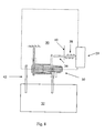
- Figure 8 illustrates a two-part system having a first part 30 connected via a hinge 50 to a second part 32.
- the reference numerals from Figure 5 have been omitted in order to retain the clarity of the figure.
- the part 30 of the system of Figure 8 has a spring loosening mechanism having a push button 29 connected to a loosening mechanism 36, such as the wedge 15, and being biased by a biasing spring 38 engaging a fixed element 40 in the part 30.
- the first part 30 is further rotationally attached to the second part 32 by an element 42. This is only to stabilize the rotation of the parts.
- the mobile telephone 28 has the first and second parts 30 and 32 as well as a hinge or clutch illustrated at 33, a release mechanism 34 for the hinge 33.
- Figure 9 illustrates three different angles between the first part 30 and the second part 32 and therefore a specific use of the mobile telephone 28.
- the mobile telephone 28 will be stored as illustrated in the left-most drawing where the first and second parts 30 and 32 are adjacent to each other.
- the second part 32 has a microphone 36 protected in the position in the left-most illustration.
- the telephone 28 also has a speaker 39 in the first part 30.
- the hinge 33 is provided in the telephone 28 so that the rod member 14 is attached to the second part 32 and so that the rod member 12 and/or the end 18 is attached to the first part 30. Also, a release mechanism as that illustrated by the wedge 15 is operatively connected to the button 34. The spring 16 is directed so that the rotation in the direction of the fat arrow (see Figs. 2 or 3 ) will take place when rotating the second part 32 as illustrated by the fat arrow in the middle illustration of Figure 9 .
- the second part 32 is rotated as illustrated by the fat arrow in the middle illustration. In this manner, the microphone becomes accessible. This activation is obtained by releasing the release mechanism 34, which loosens the spring 16 and allows the biasing means to overcome the third friction and rotate the second part 32 to e.g. a stopping position as that illustrated in the middle illustration.
- This position may be pre-defined as that providing the optimal position for use when making a telephone call. This position may also be one where the second part 32 is rotated further in the direction of the fat arrow.
- the release button 34 is disengaged.
- the second part 32 may be rotated in a direction opposite to that illustrated by the fat arrow. Due to the friction of the hinge 33 - as well as the operation of the biasing means, the second part 32 will be substantially fixed and will be able to e.g. hold the telephone at the desired angle or in the desired position.
- the telephone 28 may also have a locking means 37 for maintaining the second part 32 in the closed position even if the release button 34 is operated.
- the hinge may be reversed to that a snap closing is achieved by operating the button 34.
- the parts are rotated by hand (in the low friction direction of the hinge), and are maintained in that angular position until the button is operated, where after the biasing spring will close the parts again.
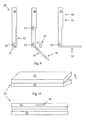
- FIG. 10 a further embodiment is seen at an angle from the back (above) and directly from the front (below).
- This embodiment 50 may also be a telephone or a palm computer having two parts 52 and 54 interconnected by a hinge (not illustrated) and having a release button 56 to be used as described above.
- operation of the release button 56 may make the biasing means open the telephone/computer 50 for operation. Releasing the release button will make further rotation in the opening direction (the fat arrow) difficult (due to the high friction), but rotation in the opposite direction (the closing direction) will be easy.
- any desired angle between the parts may be obtained at the same time as a snap opening (the operation of the biasing means) may be obtained.
- the present embodiments have centred on mobile telephones.
- the same functionality may be obtained in any type of element where a combination of an automatic opening of a device is desired combined with a subsequent, freely selected positioning of the elements.
- This may be in hand-held or palm-size electronic systems, portable computers or toys of any type.
Landscapes
- Engineering & Computer Science (AREA)
- Computer Hardware Design (AREA)
- Theoretical Computer Science (AREA)
- Physics & Mathematics (AREA)
- Human Computer Interaction (AREA)
- General Engineering & Computer Science (AREA)
- General Physics & Mathematics (AREA)
- Signal Processing (AREA)
- Mathematical Physics (AREA)
- Computer Networks & Wireless Communication (AREA)
- Mechanical Engineering (AREA)
- Telephone Set Structure (AREA)
- Pivots And Pivotal Connections (AREA)
Description
- The present Invention relates to a hinge for a mobile terminal, such as a mobile telephone, and to a novel type of hinge, which may be used for mobile terminals.
- Presently, mobile terminals may be made as two-part terminals where the two parts are able to rotate in relation to each other from an inactive position to an active position. Some of these terminals have a snap opening function whereby the rotation to the active position is automatic upon activation of a button. However, due to the biasing, the active position and the inactive positions are the only positions maintainable. Thus, this brings about a problem when e.g. trying to position the terminal in a manner so that a display or the like may be visible.
-
US 5784759 discloses A hinge construction has a fixed hinge member and a movable hinge member fixed to a mandrel, the mandrel being rotatably supported on the fixed hinge member, and a single coil spring one end of which is anchored immovably to the fixed hinge member the other end being free the coil spring closely surrounding the mandrel, an interior surface of the spring being in contact only with the mandrel, the arrangement being such that movement of the movable hinge member in one direction rotates the mandrel in a sense acting to uncoil the coil-spring thus allowing free movement of the movable hinge member whereas movement of the movable hinge member in the opposite direction acts to cause the coil-spring to tighten about the mandrel and thus resist movement. - It has been found that it is desirable to have, in a mobile terminal, a more freely selectable angle or rotation between such two parts.
- Thus, in a first aspect, the invention relates to a mobile terminal having two parts connected to each other by a hinge, the hinge comprising:
- a helical spring having a longitudinal axis, the spring comprising one or more wound strands of material, each strand having two ends,
- a first hinge part extending into the helical spring, contacting an inner part of the helical spring at a first position or area along the longitudinal axis, and being connected to or attached to a first part of the two parts, and
- a second hinge part contacting the one or more strands of the helical spring and being connected to or attached to a second part of the two parts,
- rotation of the first hinge part in a first direction around the longitudinal axis and in relation to the second hinge part will provide a first, lower friction between the first hinge part and the helical spring, and
- rotation of the first hinge part in a second direction, being opposite to the first direction, around the longitudinal axis and in relation to the second hinge part will provide a second, higher friction between the first hinge part and the helical spring
- release means for increasing a diameter of the helical spring at the first position or area in order to reduce the second, higher friction between the first hinge part and the helical spring during rotation of the first hinge part in the second direction, the second, higher friction being reduced to a third friction, and
- biasing means for providing a rotation of the first hinge part in the second direction when the release means are operated,
- In this context, it should be noted that the hinge may have other, more standard, hinge means, whereby the present helical spring assembly may mostly be used as a rotatable clutch of the hinge.
- A standard helical spring is normally made of only a single strand or elongated piece of the material (typically a metal or another stiff material). However, springs are contemplated being formed by a number of strands, the windings of which are positioned, one after the other, along the longitudinal axis of the spring.
- Also, the helical spring needs only be formed by part of the strand(s). The ends of the strand(s) need not be part of the helical spring. These ends may be used for different purposes, such as immobilization or actual movement.
- The normal manner of providing a wrap spring clutch is to have the two hinged or clutched elements extend into the spring and thereby engage the inner part of the spring. However, it should be noted that the same effect may be obtained by reversing the operation and engaging the spring at an outer side thereof. Thus, in order to loosen the engagement, the spring is then not loosened (diameter increased) but tightened (diameter reduced).
- In this context, the first hinge part would normally extend into the spring from one end thereof and engage the inner side of the spring (at least in the clutched operation) along a position and area from that end and a predetermined distance into the spring along the axis. However, the part needs not contact the spring at the end but may do so at any position thereof.
- The first hinge part preferably has, at the part extending into the spring, an at least substantially circular cross section corresponding to an inner cross section of the spring. In that manner, contact inside the spring may be a contact along the inner circumference of the spring.
- The contact of the second hinge part and the spring may be an attachment or a biasing, depending on which type of movement of the spring the second hinge part is to prevent or brake.
- If both the first and second hinge parts extend into the spring, the first and second hinge parts engage or contact the spring at different positions or areas along the longitudinal axis of the spring. The first hinge part extends into the spring, but the second one may engage an outer surface thereof, an inner surface thereof, or actually a part of the strand(s) not being part of the actual helical shape of the spring. This will become clearer below.
- It is clear that friction is a manner of keeping two elements in a predetermined position until a force is experienced large enough to overcome the friction, where after rotation is obtained.
- The operation and direction of the biasing force results in that the biasing means is not able to actually rotate the parts until the release means of the hinge is operated, whereby the second friction is reduced to the third friction. It is seen that the release thus provides a snap/automatic movement of the pertaining parts of the terminal. However, the hinge provides, at the same time, a freely selected rotational position of the two parts in that the biasing or snap action is only provided when the release means is operated.
- In one embodiment, the spring comprises a non-helical part at an end of each of the one or more strands, and the second hinge part contacts only the non-helical part. Thus, the second hinge part does not actually extend into the spring and/or engage the inner part thereof. In this embodiment, the contact between the second hinge part and the non-helical part of the spring may be an attachment. Preferably, the first hinge member contacts at least substantially a full inner surface of the spring and/or extends a full length of the helical part of the spring (in the direction of the axis).
- In another embodiment, one end of each of the strand(s) of the spring is fixed in relation to the second hinge part and the release means is adapted to displace the other end(s) of the strand(s) from a first position to a second position. In this embodiment, the release means are preferably adapted to not be rotated in relation to the second hinge part in order to facilitate the design of the release mechanism.
- It may be desired to actually ensure that an accidental operation of the release means does not bring about rotation. Thus, the terminal could further comprise locking means for maintaining the parts in a predetermined rotational angle even when the release means are operated.
- One manner of obtaining this displacement is one wherein the release means comprises, for each hinge, a wedge-shaped element adapted to be translated and thereby displace the end(s).
- Another manner is one wherein the release means comprises, for each hinge, a flexible element engaging the end(s), the end(s) being adapted to bias the flexible element into a first, deformed state when in the first position, and the release means comprising means for bringing the flexible element into a first, regular state and thereby bringing the end(s) into the second position. This may be obtained when the flexible element is hollow and wherein the means for bringing comprise a means adapted to be translated into the hollowness of the flexible element. These bringing means may be translatable into and out of the flexible element and may be biased in a direction out of the hollowness so as to ensure that the end returns to the first position and that engagement is obtained between the first hinge part and the spring.
- A second aspect of the invention relates to a hinge or a clutch for facilitating rotational movement of a first hinge part in relation to a second hinge part and around a rotational axis of the hinge, the hinge comprising:
- a helical spring having a longitudinal axis along the rotational axis, the spring comprising one or more wound strands of material, each strand having two ends and a part extending outside the helical spring,
- the first hinge part extending into the helical spring, contacting an inner part of the helical spring at a first position or area along the longitudinal axis, and
- a second hinge part being attached only to the extending parts of each of the one or more strands of the helical spring,
- the spring facilitating that:
- rotation of the first hinge part in a first direction around the longitudinal axis and in relation to the second hinge part will provide a first, lower friction between the first hinge part and the helical spring, and
- rotation of the first hinge part In a second direction, being opposite to the first direction, around the longitudinal axis and in relation to the second hinge part will provide a second, higher friction between the first hinge part and the helical spring.
- Thus, the second hinge part does not contact the spring inside the helical part thereof - or at least does not contact the spring in the helical part. Contacting the spring at an end of the strands, such as ends not forming part of the helical spring but extend away there from, may render the mass production of this hinge or clutch more controllable.
- Naturally, this hinge preferably comprises release means for increasing a diameter of the helical spring at the first position or area in order to reduce the second, higher friction between the first hinge part and the helical spring during rotation of the first hinge part in the second direction, the second, higher friction being reduced to a third friction
- Also, the hinge preferably further comprises biasing means for providing a rotation of the first hinge part in the second direction when the release means are operated, the biasing means providing a force exceeding a force required to overcome the third friction but being lower than a force required to overcome the second friction. In this situation, both the automatic rotation and the freely selectable position are possible.
- In one embodiment, again, the release means comprises, for each hinge, a wedge-shaped element adapted to be translated and displace the end(s).
- In another embodiment, the release means comprises, for each hinge, a flexible element engaging the end(s), the end(s) being adapted to bias the flexible element into a first, deformed state when in the first position, and the release means comprising means for bringing the flexible element into a first, regular state and thereby bringing the end(s) into the second position. This flexible element could be hollow and the means for bringing could then comprise a means adapted to be translated into the hollowness of the flexible element. Also, then the bringing means are preferably adapted to be translated into and out of the flexible element and are biased in a direction out of the hollowness.
- A third aspect of the invention relates to a method of operating a mobile terminal according the first aspect of the invention, the method comprising:
- operating the release means so as to have the biasing means rotate the first hinge part from an initial position in the second direction in relation to the second hinge means through a first angle to a second position,
- disengaging the release means,
- rotating the first hinge part in the second direction and through a second angle being smaller than the first angle to a third position, and
- allowing the hinge to maintain the first hinge part in the third position.
- Thus, using this method, the automatic opening and the then freely selectable position is obtained.
- In the following, preferred embodiments of the invention will be described with reference to the drawing, wherein:
-
Figure 1 illustrates the parts of a clutch/hinge, -
Figure 2 illustrates the parts ofFigure 1 assembled to the hinge, -
Figure 3 illustrates a different embodiment of a hinge, -
Figure 4 is a cut-through view of yet an embodiment of a hinge, -
Figure 5 , is a cut-through view of the hinge ofFigure 4 now also having a biasing spring, -
Figure 6 illustrates one manner of loosening the helical spring, -
Figure 7 illustrates another embodiment of a manner of loosening the helical spring, -
Figure 8 illustrates a system having two parts, a hinge as seen inFigure 5 and a spring loosening means, -
Figure 9 illustrates three different positions or angles between a mobile telephone body and a movable part thereof, and -
Figure 10 illustrates an embodiment different from that ofFigure 9 . -
Figure 1 illustrates the basic elements of a known wrap-spring clutch/hinge. Thishinge 10 comprises tworod members helical spring 16 having aninternal surface 17 and two strand ends 18 and 20. The diameters of therod members spring 16. - This hinge is assembled in
Figure 2 where the rod members touch inside thespring 16. It is clear that if theend 18 is kept fixed in relation to therod member 12, rotation of therod member 14 in the direction of the arrow will tighten thespring 16 and thus lock the tworod members rod member 14 torod member 12. On the other hand, if therod member 14 was rotated in the other direction (opposite to the arrow), this movement will only loosen thespring 16, whereby almost no torque is transferred. - Also illustrated in
Figure 2 is awedge 15 which may be used for moving theend 20 of thespring 16. If the wedge is moved so as to lift (on the figure) theend 20, thespring 16 will be "loosened" which means that the internal diameter thereof will increase so that therod member 14 may now be moved in the direction of the fat arrow without tightening thespring 16 and transferring torque to therod member 12. - In that manner, rotation of the
member 14 in the direction of the fat arrow, around the longitudinal axis A, without operating therelease wedge 15, a high friction is obtained due to the fact that thespring 16 will tighten. Rotation in the opposite direction of themember 14 will, on the other hand, incur a much lower friction due to thespring 16 loosening. Also, when operating thewedge 15, a third, low friction is experienced when rotating themember 14 in the direction of the fat arrow. - In
Figure 3 , a different embodiment is illustrated which also has therod member 14 and thespring 16 with theends rod member 12 has been removed, and instead the element hitherto connected to therod member 12 is attached to theend 18. As described above, this embodiment has certain advantages to the embodiment where the rod members abut in thespring 16. Preferably, therod 14 now extends throughout the whole of thehelical spring 16. -
Figure 4 illustrates another embodiment of a hinge having the same function. This hinge also has afirst rod member 12, the second rod member 14 - now in the form of a tubular element extending over part of therod member 12. Thespring 16 has the "unlocking end" 20 and theend 18, which is now fixed to a fixed element. - In
Figure 5 , the hinge ofFigure 4 has been added elements 30 (fixed to therod member 12 and in which theend 18 is fixed) and 32 (fixed to rod member 14) as well as a lockingelement 42 preventing thespring 16 from moving into a space between therods end 18, theelement 30 may be immobilized. Also, a biasingspring 44 is added having one end attached to theelement 32 and the other (not illustrated) fixed to therod member 12. Thus, it is clear that theelement 32 and rod member14 may be rotated over therod member 12, this movement being biased by the biasingspring 44. - In this respect, it is preferred that the
fixed end 18 and the wedge 15 (see alsoFigures 6 and 7 ) exist in the same system - meaning that these elements are not rotatable (but may be translatable) in relation to therod member 12 orelement 30. This will become clear fromFigure 8 . - A number of choices exist when assembling the present hinge. Either the
spring 16 is slightly opened before introducing therods 12 and 14 (when the outer diameter of the rods is larger than the inner diameter of the spring) so as to obtain an engagement or friction there between in the un-operated situation (when the outer diameter of the rods is smaller than the inner diameter of the spring), so that operation may be a loosening of thespring 16. Alternatively, it may be desired to actually bias theend 20 in the un-operated situation, so that operation may be a tightening of thespring 16. In either way, it may be desired to bias theend 20 in the "tightening" direction in the un-operated situation. -
Figures 6 and 7 illustrate different manners of actually loosening thespring 16. InFigure 6 , thewedge 15 is illustrated together with two different positions of theend 20 of thespring 16. Depending on the distance between thewedge 15 and the helical part of thespring 16, this movement of theend 20 will provide more or less loosening of thespring 16. - In
Figure 6 , thewedge 15 is supplemented by another element 15' forming, together with the wedge 15 a track in which theend 20 travels. This track may be used for actually biasing theend 20 in the tightening direction. This operation is seen as the un-biased position of theend 20 is illustrated by a dotted end 20'. Thus, moving theend 20 upwards will loosen the spring, and in the un-operated position, theend 20 is that depicted at the lower position, which is lower than the unbiased position 20'. - Another manner is seen in
Figure 7 , where theend 20 rests against aflexible element 24 inside which an elongated,stiff element 26 may slide. It is seen that theend 20, in fact, is biased against theelement 24 in such a manner that when theelement 26 is retracted, theend 20 will deform theelement 24 and thereby tighten thespring 16. - The
element 26 is biased away from and out of theelement 24 by a biasingspring 27, and theelements means 22. - Returning to
Figure 2 , it is clear that loosening of thespring 16 may be performed by moving thespring end 20 in a number of ways, such as in the direction of the fat arrow or in a direction along theend 20 toward thespring 16. -
Figure 8 illustrates a two-part system having afirst part 30 connected via ahinge 50 to asecond part 32. The reference numerals fromFigure 5 have been omitted in order to retain the clarity of the figure. - The actual "direction" of the hinge (that is, the high friction and low friction rotation directions and the directions of the biasing springs) will depend on the actual embodiment. Two embodiments are described in relation to
Figures 9 and 10 . - The
part 30 of the system ofFigure 8 has a spring loosening mechanism having apush button 29 connected to aloosening mechanism 36, such as thewedge 15, and being biased by a biasingspring 38 engaging a fixedelement 40 in thepart 30. - The
first part 30 is further rotationally attached to thesecond part 32 by anelement 42. This is only to stabilize the rotation of the parts. - In
Figure 9 , themobile telephone 28 has the first andsecond parts release mechanism 34 for thehinge 33. -
Figure 9 illustrates three different angles between thefirst part 30 and thesecond part 32 and therefore a specific use of themobile telephone 28. - In normal non-operative use, the
mobile telephone 28 will be stored as illustrated in the left-most drawing where the first andsecond parts second part 32 has amicrophone 36 protected in the position in the left-most illustration. Thetelephone 28 also has a speaker 39 in thefirst part 30. - The
hinge 33 is provided in thetelephone 28 so that therod member 14 is attached to thesecond part 32 and so that therod member 12 and/or theend 18 is attached to thefirst part 30. Also, a release mechanism as that illustrated by thewedge 15 is operatively connected to thebutton 34. Thespring 16 is directed so that the rotation in the direction of the fat arrow (seeFigs. 2 or 3 ) will take place when rotating thesecond part 32 as illustrated by the fat arrow in the middle illustration ofFigure 9 . - In order to operate the
telephone 28, such as when wishing to make a telephone call, thesecond part 32 is rotated as illustrated by the fat arrow in the middle illustration. In this manner, the microphone becomes accessible. This activation is obtained by releasing therelease mechanism 34, which loosens thespring 16 and allows the biasing means to overcome the third friction and rotate thesecond part 32 to e.g. a stopping position as that illustrated in the middle illustration. This position may be pre-defined as that providing the optimal position for use when making a telephone call. This position may also be one where thesecond part 32 is rotated further in the direction of the fat arrow. - Having obtained that position of the
second part 32, therelease button 34 is disengaged. - Having e.g. made the telephone call, it may be desired to have a different angle on the
second part 32 such as in order for thetelephone 28 to be able to stand up and present adisplay 31 thereof to the user. Thus, thesecond part 32 may be rotated in a direction opposite to that illustrated by the fat arrow. Due to the friction of the hinge 33 - as well as the operation of the biasing means, thesecond part 32 will be substantially fixed and will be able to e.g. hold the telephone at the desired angle or in the desired position. - The
telephone 28 may also have a locking means 37 for maintaining thesecond part 32 in the closed position even if therelease button 34 is operated. - Naturally, the hinge may be reversed to that a snap closing is achieved by operating the
button 34. Thus, the parts are rotated by hand (in the low friction direction of the hinge), and are maintained in that angular position until the button is operated, where after the biasing spring will close the parts again. - Finally, in
Figure 10 , a further embodiment is seen at an angle from the back (above) and directly from the front (below). Thisembodiment 50 may also be a telephone or a palm computer having twoparts release button 56 to be used as described above. - Thus, operation may be as described above: operation of the
release button 56 may make the biasing means open the telephone/computer 50 for operation. Releasing the release button will make further rotation in the opening direction (the fat arrow) difficult (due to the high friction), but rotation in the opposite direction (the closing direction) will be easy. - Again, any desired angle between the parts may be obtained at the same time as a snap opening (the operation of the biasing means) may be obtained.
- The present embodiments have centred on mobile telephones. However, the same functionality may be obtained in any type of element where a combination of an automatic opening of a device is desired combined with a subsequent, freely selected positioning of the elements. This may be in hand-held or palm-size electronic systems, portable computers or toys of any type.
Claims (16)
- A hinge (10,33,50) for facilitating rotational movement of a first hinge part (12,30) in relation to a second hinge part (14,32) and around a rotational axis of the hinge (10,33,50), the hinge (10,33,50) comprising:- a helical spring (16) having a longitudinal axis along the rotational axis, the spring (16) comprising one or more wound strands of material, each strand having two ends (18,20) and a part extending outside the helical spring,- the first hinge part (12,30) extending into the helical spring (16), contacting an inner part (17) of the helical spring (16) at a first position or area along the longitudinal axis, and- a second hinge part (14,32) being attached to the extending parts of each of the one or more strands of the helical spring (16),the spring (16) facilitating that:- rotation of the first hinge part (12,30) in a first direction around the longitudinal axis and in relation to the second hinge part (14,32) will provide a first, lower friction between the first hinge part (12,30) and the helical spring, and- rotation of the first hinge part (12,30) in a second direction, being opposite to the first direction, around the longitudinal axis and in relation to the second hinge part (14,32) will provide a second, higher friction between the first hinge part (12,30) and the helical spring,characterised in that the hinge further comprises:release means (15,34,56) for increasing a diameter of the helical spring (16) at the first position or area in order to reduce the second, higher friction between the first hinge part (12,30) and the helical spring (16) during rotation of the first hinge part (12,30) in the second direction, the second, higher friction being reduced to a third friction, andbiasing means (27,38,44) for providing a rotation of the first hinge part (12,30) in the second direction when the release means (15,34,56) are operated, the biasing means (27,38,44) providing a force exceeding a force required to overcome the third friction but being lower than a force required to overcome the second friction.
- A hinge according to claim 1, wherein the release means (15,34,56) comprises, for each hinge, a wedge-shaped element (15) adapted to be translated and displace the end(s).
- A hinge according to claim 1, wherein the release means (15,34,56) comprises, for each hinge, a flexible element engaging the end(s), the end(s) being adapted to bias the flexible element into a first, deformed state when in the first position, and the release means (15,34,56) comprising means for bringing the flexible element into a first, regular state and thereby bringing the end(s) into the second position.
- A hinge according to claim 3, wherein the flexible element is hollow and wherein the means for bringing comprise a means adapted to be translated into the hollowness of the flexible element.
- A hinge according to claim 3 or 4, wherein the bringing means are adapted to be translated into and out of the flexible element and are biased in a direction out of the hollowness.
- A mobile terminal having two parts connected to each other by a hinge of any of claims 1 to 5.
- A mobile terminal according to claim 6, wherein the second hinge part extends into the helical spring, contacting the inner part of the helical spring at a second position or area along the longitudinal axis.
- A mobile terminal according to claim 6, wherein the spring comprises a non-helical part at an end of each of the one or more strands, and where the second hinge part contacts the non-helical part.
- A mobile terminal according to any of claims 6 to 8, wherein one end of each of the strand(s) of the spring is fixed in relation to the second hinge part and wherein the release means (15,34,56) is adapted to displace the other end(s) of the strand(s) from a first position to a second position.
- A mobile terminal according to claim 9, wherein the release means (15,34,56) is adapted to not be rotated in relation to the second hinge part.
- A mobile terminal according to any of claims 6 to 10, further comprising locking means for maintaining the parts in a predetermined rotational angle even when the release means (15,34,56) are operated.
- A mobile terminal according to any of claims 6 to 11, wherein the release means (15,34,56) comprises, for each hinge, a wedge-shaped element adapted to be translated and displace the end(s).
- A mobile terminal according to any of claims 6 to 12, wherein the release means (15,34,56) comprises, for each hinge, a flexible element engaging the end(s), the end(s) being adapted to bias the flexible element into a first, deformed state when in the first position, and the release means (15,34,56) comprising means for bringing the flexible element into a first, regular state and thereby bringing the end(s) into the second position.
- A mobile terminal according to claim 13, wherein the flexible element is hollow and wherein the means for bringing comprise a means adapted to be translated into the hollowness of the flexible element.
- A mobile terminal according to claim 13 or 14, wherein the bringing means are adapted to be translated into and out of the flexible element and are biased in a direction out of the hollowness.
- A method of operating a mobile terminal according to any of claims 6 to 15, the method comprising:- operating the release means (15,34,56) so as to have the biasing means (27,38,44) rotate the first hinge part from an initial position in the second direction in relation to the second hinge means through a first angle to a second position,- disengaging the release means (15,34,56),- rotating the first hinge part in the second direction and through a second angle being smaller than the first angle to a third position, and- allowing the hinge to maintain the first hinge part in the third position.
Applications Claiming Priority (3)
| Application Number | Priority Date | Filing Date | Title |
|---|---|---|---|
| US10/323,823 US7079874B2 (en) | 2002-12-20 | 2002-12-20 | Transformer hinge design |
| US323823 | 2002-12-20 | ||
| PCT/DK2003/000880 WO2004057139A1 (en) | 2002-12-20 | 2003-12-15 | A mobile terminal with a hinge, a method of operating the mobile terminal and a hinge |
Publications (2)
| Publication Number | Publication Date |
|---|---|
| EP1573159A1 EP1573159A1 (en) | 2005-09-14 |
| EP1573159B1 true EP1573159B1 (en) | 2013-03-20 |
Family
ID=32680719
Family Applications (1)
| Application Number | Title | Priority Date | Filing Date |
|---|---|---|---|
| EP03779738A Expired - Lifetime EP1573159B1 (en) | 2002-12-20 | 2003-12-15 | A mobile terminal with a hinge, a method of operating the mobile terminal and a hinge |
Country Status (6)
| Country | Link |
|---|---|
| US (2) | US7079874B2 (en) |
| EP (1) | EP1573159B1 (en) |
| KR (1) | KR100807158B1 (en) |
| CN (1) | CN1754035B (en) |
| AU (1) | AU2003287898A1 (en) |
| WO (1) | WO2004057139A1 (en) |
Families Citing this family (18)
| Publication number | Priority date | Publication date | Assignee | Title |
|---|---|---|---|---|
| US20040253999A1 (en) * | 2003-06-16 | 2004-12-16 | Sergio Castaneda | Attachability enhanced wireless phone |
| KR100678265B1 (en) * | 2005-01-11 | 2007-02-02 | 삼성전자주식회사 | Semi Automatic Swing Device of Mobile Terminal |
| KR101339055B1 (en) * | 2006-03-27 | 2014-01-02 | 사우스코 인코포레이티드 | Display mounting apparatus |
| TWI364647B (en) * | 2007-07-13 | 2012-05-21 | Asustek Comp Inc | Overturning cover mechanism and electronic device using the same |
| EP2187118A1 (en) * | 2008-11-13 | 2010-05-19 | Derungs Licht AG | Hinged bracket with swivel joint |
| JP5918232B2 (en) | 2010-07-08 | 2016-05-18 | サウスコ,インコーポレイティド | Display support device |
| US9483084B2 (en) * | 2013-09-27 | 2016-11-01 | Intel Corporation | Frictional hinge for electronic devices |
| EP2910720A1 (en) * | 2014-02-18 | 2015-08-26 | Gealan Formteile GmbH | Variable operating mechanism |
| US9447620B2 (en) | 2014-09-30 | 2016-09-20 | Microsoft Technology Licensing, Llc | Hinge mechanism with multiple preset positions |
| US9600034B2 (en) * | 2015-02-13 | 2017-03-21 | Google Inc. | Attaching computing device to mount by magnets |
| US9752361B2 (en) * | 2015-06-18 | 2017-09-05 | Microsoft Technology Licensing, Llc | Multistage hinge |
| US9864415B2 (en) | 2015-06-30 | 2018-01-09 | Microsoft Technology Licensing, Llc | Multistage friction hinge |
| US11131423B2 (en) | 2016-03-07 | 2021-09-28 | Southco, Inc. | Display support arm assembly for mounting a display |
| US10344797B2 (en) | 2016-04-05 | 2019-07-09 | Microsoft Technology Licensing, Llc | Hinge with multiple preset positions |
| US10037057B2 (en) | 2016-09-22 | 2018-07-31 | Microsoft Technology Licensing, Llc | Friction hinge |
| WO2019141883A1 (en) * | 2018-01-19 | 2019-07-25 | Rodriguez Abesamis Alejandro | Protection device for a mobile telephone with automatic opening |
| USD964337S1 (en) | 2019-01-22 | 2022-09-20 | Alejandro Rodriguez Abesamis | Protection device for a mobile telephone with automatic opening |
| JP7698283B2 (en) * | 2021-03-22 | 2025-06-25 | 株式会社ナチュラレーザ・ワン | Switchgear and terminal equipment using said switchgear |
Family Cites Families (34)
| Publication number | Priority date | Publication date | Assignee | Title |
|---|---|---|---|---|
| JPH0640311Y2 (en) | 1988-12-21 | 1994-10-19 | 日本発条株式会社 | Axis locking device |
| CA2109204C (en) * | 1992-03-11 | 1996-04-09 | Paul John Kudrna | Hinge assembly |
| US5784759A (en) | 1993-11-02 | 1998-07-28 | King; David Russell | Hinge construction |
| US5564163A (en) | 1994-11-08 | 1996-10-15 | Cema Technologies, Inc. | Lockable hinge assembly |
| AU4502596A (en) * | 1994-11-28 | 1996-06-19 | Ericsson Inc. | Portable telephone with an asymmetric hinged housing configuration |
| JP3737160B2 (en) | 1995-03-31 | 2006-01-18 | 富士通株式会社 | Folding mobile phone hinge mechanism and folding mobile phone |
| US5649309A (en) * | 1995-05-18 | 1997-07-15 | Motorola, Inc. | Wireless communication device having an axially aligned cover release mechanism |
| US5525667A (en) * | 1995-08-02 | 1996-06-11 | Tenneco Plastics, Inc. | Polymer orientation |
| US5697125A (en) * | 1995-11-27 | 1997-12-16 | Reell Precision Manufacturing Corporation | Clip friction hinge |
| US5813093A (en) * | 1997-01-31 | 1998-09-29 | Lucent Technologies Inc. | Hinge assembly |
| US6256481B1 (en) * | 1997-04-26 | 2001-07-03 | Samsung Electronics Co., Ltd. | Microphone connecting device for flip type portable telephone |
| WO1998053637A1 (en) * | 1997-05-21 | 1998-11-26 | E.S.P. Communications, Inc. | System, method and apparatus for 'caller only' initiated two-way wireless communication with caller generated billing |
| JP3732619B2 (en) * | 1997-06-16 | 2006-01-05 | 加藤電機株式会社 | Hinge device |
| TW411069U (en) * | 1997-10-08 | 2000-11-01 | Kato Electric & Machinary Co | Hinge device |
| US5996178A (en) * | 1997-10-15 | 1999-12-07 | Motorola, Inc. | Hinge suitable for use in a foldable device |
| US5987122A (en) * | 1998-01-08 | 1999-11-16 | Qualcomm Incorporated | Portable phone with cover actuating hinge assembly |
| US6157717A (en) * | 1998-03-19 | 2000-12-05 | Qualcomm Incorporated | Snap hinge mechanism for flip style portable phone |
| US6148079A (en) * | 1998-03-19 | 2000-11-14 | Qualcomm Incorporated | Hinge apparatus for flip style portable phone |
| US6122801A (en) * | 1998-05-28 | 2000-09-26 | Telefonaktiebolaget Lm Ericsson | Hinge mechanism |
| US6104621A (en) * | 1998-06-30 | 2000-08-15 | Ericsson, Inc. | Torsional hinging mechanism |
| SE516906C2 (en) * | 1999-03-23 | 2002-03-19 | Ericsson Telefon Ab L M | Device on a mobile phone comprising a pivotal protective cover which when opened opens a predetermined open position |
| JP2000278373A (en) * | 1999-03-29 | 2000-10-06 | Ricoh Co Ltd | Portable electronic devices |
| JP2001103568A (en) * | 1999-09-30 | 2001-04-13 | Toshiba Corp | Communication system, mobile communication device, portable information processing device, and data communication method used in this communication system |
| US6296215B1 (en) | 1999-12-15 | 2001-10-02 | Group Dekko Services, Llc | Adjustable keyboard support |
| JP4637332B2 (en) * | 2000-08-04 | 2011-02-23 | パナソニック株式会社 | Folding portable wireless device |
| US6678539B1 (en) * | 2001-01-22 | 2004-01-13 | Lu Sheng-Nan | Mobile phone cover hinge |
| WO2002068833A1 (en) * | 2001-02-26 | 2002-09-06 | Sugatsune Kogyo Co., Ltd. | Hinge device |
| US6766180B2 (en) * | 2001-03-01 | 2004-07-20 | Qualcomm, Incorporated | Preferential deflection hinge mechanism with an idler for foldable portable electronic devices |
| JP2003120653A (en) * | 2001-10-17 | 2003-04-23 | Ohashi Technica Inc | Hinge device and cellular phone using this hinge device |
| TW576080B (en) * | 2002-03-01 | 2004-02-11 | Benq Corp | Hinge device |
| TW577213B (en) * | 2002-03-14 | 2004-02-21 | Benq Corp | Flipper phone having a hinge mechanism with auto-lock function |
| KR100469361B1 (en) * | 2002-07-24 | 2005-01-31 | 삼성전기주식회사 | Folder driving apparatus for portable phone |
| US7529571B2 (en) * | 2003-09-03 | 2009-05-05 | Samsung Electronics Co., Ltd. | Sliding/hinge apparatus for sliding/rotating type mobile terminals |
| KR100557078B1 (en) * | 2003-11-06 | 2006-03-03 | 삼성전자주식회사 | Hinge device for display rotatable mobile terminal |
-
2002
- 2002-12-20 US US10/323,823 patent/US7079874B2/en not_active Expired - Fee Related
-
2003
- 2003-12-15 CN CN2003801098524A patent/CN1754035B/en not_active Expired - Fee Related
- 2003-12-15 AU AU2003287898A patent/AU2003287898A1/en not_active Abandoned
- 2003-12-15 EP EP03779738A patent/EP1573159B1/en not_active Expired - Lifetime
- 2003-12-15 KR KR1020057011488A patent/KR100807158B1/en not_active Expired - Fee Related
- 2003-12-15 WO PCT/DK2003/000880 patent/WO2004057139A1/en not_active Ceased
- 2003-12-15 US US10/539,168 patent/US20060188092A1/en not_active Abandoned
Also Published As
| Publication number | Publication date |
|---|---|
| US7079874B2 (en) | 2006-07-18 |
| KR100807158B1 (en) | 2008-02-27 |
| AU2003287898A1 (en) | 2004-07-14 |
| HK1087751A1 (en) | 2006-10-20 |
| KR20050084432A (en) | 2005-08-26 |
| US20060188092A1 (en) | 2006-08-24 |
| WO2004057139A1 (en) | 2004-07-08 |
| US20040198412A1 (en) | 2004-10-07 |
| CN1754035B (en) | 2011-09-07 |
| CN1754035A (en) | 2006-03-29 |
| EP1573159A1 (en) | 2005-09-14 |
Similar Documents
| Publication | Publication Date | Title |
|---|---|---|
| US7079874B2 (en) | Transformer hinge design | |
| US20030116596A1 (en) | Wearable electronic device | |
| JP3183342B2 (en) | Hinge structure | |
| US7832056B2 (en) | Opening-closing device | |
| JP5007236B2 (en) | Switchgear and portable device using the same | |
| US20020069483A1 (en) | Apparatus for opening hand held electronic device | |
| JPWO2002077472A1 (en) | Hinge structure with rotary actuator | |
| JP4205367B2 (en) | Electronics | |
| JP2007267238A (en) | Portable device | |
| WO2004027274A1 (en) | Hinge device | |
| US20010036265A1 (en) | Automatic opening and closing apparatus for mobile phones | |
| JP2001251396A (en) | Foldable mobile phone | |
| US7353048B2 (en) | Transformer hinge design | |
| JP2001251399A (en) | Foldable mobile phone | |
| JP2011511915A (en) | Hinge mechanism for wireless communication device | |
| CN101360925A (en) | Opening and closing device and portable equipment using the same | |
| JP3544949B2 (en) | Hinge device and portable electronic device using hinge device | |
| JP4546888B2 (en) | HINGE DEVICE AND ELECTRONIC DEVICE USING HINGE DEVICE | |
| JP3145663B2 (en) | Hinge device | |
| JP4436996B2 (en) | 2-part device | |
| JP3656041B2 (en) | HINGE DEVICE AND ELECTRONIC DEVICE USING HINGE DEVICE | |
| HK1087751B (en) | A mobile terminal with a hinge, a method of operating the mobile terminal and a hinge | |
| JP2003247530A (en) | Information processing equipment | |
| JP2001057501A (en) | Antenna telescopic operation device | |
| KR101013770B1 (en) | Damping Hinges for Folding Handheld Terminals |
Legal Events
| Date | Code | Title | Description |
|---|---|---|---|
| PUAI | Public reference made under article 153(3) epc to a published international application that has entered the european phase |
Free format text: ORIGINAL CODE: 0009012 |
|
| 17P | Request for examination filed |
Effective date: 20050613 |
|
| AK | Designated contracting states |
Kind code of ref document: A1 Designated state(s): AT BE BG CH CY CZ DE DK EE ES FI FR GB GR HU IE IT LI LU MC NL PT RO SE SI SK |
|
| AX | Request for extension of the european patent |
Extension state: AL LT LV MK |
|
| DAX | Request for extension of the european patent (deleted) | ||
| RIN1 | Information on inventor provided before grant (corrected) |
Inventor name: BARNETT, RICKY Inventor name: FERRANTI, GIOVANNI Inventor name: PONTOPPIDAN, MORTEN |
|
| 17Q | First examination report despatched |
Effective date: 20120208 |
|
| GRAP | Despatch of communication of intention to grant a patent |
Free format text: ORIGINAL CODE: EPIDOSNIGR1 |
|
| GRAS | Grant fee paid |
Free format text: ORIGINAL CODE: EPIDOSNIGR3 |
|
| GRAA | (expected) grant |
Free format text: ORIGINAL CODE: 0009210 |
|
| AK | Designated contracting states |
Kind code of ref document: B1 Designated state(s): AT BE BG CH CY CZ DE DK EE ES FI FR GB GR HU IE IT LI LU MC NL PT RO SE SI SK |
|
| REG | Reference to a national code |
Ref country code: GB Ref legal event code: FG4D |
|
| REG | Reference to a national code |
Ref country code: CH Ref legal event code: EP |
|
| REG | Reference to a national code |
Ref country code: IE Ref legal event code: FG4D |
|
| REG | Reference to a national code |
Ref country code: AT Ref legal event code: REF Ref document number: 602203 Country of ref document: AT Kind code of ref document: T Effective date: 20130415 |
|
| REG | Reference to a national code |
Ref country code: DE Ref legal event code: R096 Ref document number: 60343565 Country of ref document: DE Effective date: 20130516 |
|
| PG25 | Lapsed in a contracting state [announced via postgrant information from national office to epo] |
Ref country code: BG Free format text: LAPSE BECAUSE OF FAILURE TO SUBMIT A TRANSLATION OF THE DESCRIPTION OR TO PAY THE FEE WITHIN THE PRESCRIBED TIME-LIMIT Effective date: 20130620 Ref country code: ES Free format text: LAPSE BECAUSE OF FAILURE TO SUBMIT A TRANSLATION OF THE DESCRIPTION OR TO PAY THE FEE WITHIN THE PRESCRIBED TIME-LIMIT Effective date: 20130701 Ref country code: SE Free format text: LAPSE BECAUSE OF FAILURE TO SUBMIT A TRANSLATION OF THE DESCRIPTION OR TO PAY THE FEE WITHIN THE PRESCRIBED TIME-LIMIT Effective date: 20130320 |
|
| REG | Reference to a national code |
Ref country code: AT Ref legal event code: MK05 Ref document number: 602203 Country of ref document: AT Kind code of ref document: T Effective date: 20130320 |
|
| PG25 | Lapsed in a contracting state [announced via postgrant information from national office to epo] |
Ref country code: GR Free format text: LAPSE BECAUSE OF FAILURE TO SUBMIT A TRANSLATION OF THE DESCRIPTION OR TO PAY THE FEE WITHIN THE PRESCRIBED TIME-LIMIT Effective date: 20130621 Ref country code: FI Free format text: LAPSE BECAUSE OF FAILURE TO SUBMIT A TRANSLATION OF THE DESCRIPTION OR TO PAY THE FEE WITHIN THE PRESCRIBED TIME-LIMIT Effective date: 20130320 Ref country code: SI Free format text: LAPSE BECAUSE OF FAILURE TO SUBMIT A TRANSLATION OF THE DESCRIPTION OR TO PAY THE FEE WITHIN THE PRESCRIBED TIME-LIMIT Effective date: 20130320 |
|
| REG | Reference to a national code |
Ref country code: NL Ref legal event code: VDEP Effective date: 20130320 |
|
| PG25 | Lapsed in a contracting state [announced via postgrant information from national office to epo] |
Ref country code: BE Free format text: LAPSE BECAUSE OF FAILURE TO SUBMIT A TRANSLATION OF THE DESCRIPTION OR TO PAY THE FEE WITHIN THE PRESCRIBED TIME-LIMIT Effective date: 20130320 |
|
| PG25 | Lapsed in a contracting state [announced via postgrant information from national office to epo] |
Ref country code: EE Free format text: LAPSE BECAUSE OF FAILURE TO SUBMIT A TRANSLATION OF THE DESCRIPTION OR TO PAY THE FEE WITHIN THE PRESCRIBED TIME-LIMIT Effective date: 20130320 Ref country code: AT Free format text: LAPSE BECAUSE OF FAILURE TO SUBMIT A TRANSLATION OF THE DESCRIPTION OR TO PAY THE FEE WITHIN THE PRESCRIBED TIME-LIMIT Effective date: 20130320 Ref country code: PT Free format text: LAPSE BECAUSE OF FAILURE TO SUBMIT A TRANSLATION OF THE DESCRIPTION OR TO PAY THE FEE WITHIN THE PRESCRIBED TIME-LIMIT Effective date: 20130722 Ref country code: NL Free format text: LAPSE BECAUSE OF FAILURE TO SUBMIT A TRANSLATION OF THE DESCRIPTION OR TO PAY THE FEE WITHIN THE PRESCRIBED TIME-LIMIT Effective date: 20130320 Ref country code: RO Free format text: LAPSE BECAUSE OF FAILURE TO SUBMIT A TRANSLATION OF THE DESCRIPTION OR TO PAY THE FEE WITHIN THE PRESCRIBED TIME-LIMIT Effective date: 20130320 Ref country code: SK Free format text: LAPSE BECAUSE OF FAILURE TO SUBMIT A TRANSLATION OF THE DESCRIPTION OR TO PAY THE FEE WITHIN THE PRESCRIBED TIME-LIMIT Effective date: 20130320 Ref country code: CZ Free format text: LAPSE BECAUSE OF FAILURE TO SUBMIT A TRANSLATION OF THE DESCRIPTION OR TO PAY THE FEE WITHIN THE PRESCRIBED TIME-LIMIT Effective date: 20130320 |
|
| PG25 | Lapsed in a contracting state [announced via postgrant information from national office to epo] |
Ref country code: CY Free format text: LAPSE BECAUSE OF FAILURE TO SUBMIT A TRANSLATION OF THE DESCRIPTION OR TO PAY THE FEE WITHIN THE PRESCRIBED TIME-LIMIT Effective date: 20130320 |
|
| PLBE | No opposition filed within time limit |
Free format text: ORIGINAL CODE: 0009261 |
|
| STAA | Information on the status of an ep patent application or granted ep patent |
Free format text: STATUS: NO OPPOSITION FILED WITHIN TIME LIMIT |
|
| PG25 | Lapsed in a contracting state [announced via postgrant information from national office to epo] |
Ref country code: DK Free format text: LAPSE BECAUSE OF FAILURE TO SUBMIT A TRANSLATION OF THE DESCRIPTION OR TO PAY THE FEE WITHIN THE PRESCRIBED TIME-LIMIT Effective date: 20130320 |
|
| 26N | No opposition filed |
Effective date: 20140102 |
|
| PG25 | Lapsed in a contracting state [announced via postgrant information from national office to epo] |
Ref country code: IT Free format text: LAPSE BECAUSE OF FAILURE TO SUBMIT A TRANSLATION OF THE DESCRIPTION OR TO PAY THE FEE WITHIN THE PRESCRIBED TIME-LIMIT Effective date: 20130320 |
|
| REG | Reference to a national code |
Ref country code: DE Ref legal event code: R097 Ref document number: 60343565 Country of ref document: DE Effective date: 20140102 |
|
| REG | Reference to a national code |
Ref country code: DE Ref legal event code: R119 Ref document number: 60343565 Country of ref document: DE |
|
| REG | Reference to a national code |
Ref country code: CH Ref legal event code: PL |
|
| GBPC | Gb: european patent ceased through non-payment of renewal fee |
Effective date: 20131215 |
|
| PG25 | Lapsed in a contracting state [announced via postgrant information from national office to epo] |
Ref country code: LU Free format text: LAPSE BECAUSE OF FAILURE TO SUBMIT A TRANSLATION OF THE DESCRIPTION OR TO PAY THE FEE WITHIN THE PRESCRIBED TIME-LIMIT Effective date: 20131215 Ref country code: MC Free format text: LAPSE BECAUSE OF FAILURE TO SUBMIT A TRANSLATION OF THE DESCRIPTION OR TO PAY THE FEE WITHIN THE PRESCRIBED TIME-LIMIT Effective date: 20130320 |
|
| REG | Reference to a national code |
Ref country code: IE Ref legal event code: MM4A |
|
| REG | Reference to a national code |
Ref country code: FR Ref legal event code: ST Effective date: 20140829 |
|
| REG | Reference to a national code |
Ref country code: DE Ref legal event code: R119 Ref document number: 60343565 Country of ref document: DE Effective date: 20140701 |
|
| PG25 | Lapsed in a contracting state [announced via postgrant information from national office to epo] |
Ref country code: DE Free format text: LAPSE BECAUSE OF NON-PAYMENT OF DUE FEES Effective date: 20140701 Ref country code: LI Free format text: LAPSE BECAUSE OF NON-PAYMENT OF DUE FEES Effective date: 20131231 Ref country code: CH Free format text: LAPSE BECAUSE OF NON-PAYMENT OF DUE FEES Effective date: 20131231 Ref country code: IE Free format text: LAPSE BECAUSE OF NON-PAYMENT OF DUE FEES Effective date: 20131215 |
|
| PG25 | Lapsed in a contracting state [announced via postgrant information from national office to epo] |
Ref country code: GB Free format text: LAPSE BECAUSE OF NON-PAYMENT OF DUE FEES Effective date: 20131215 Ref country code: FR Free format text: LAPSE BECAUSE OF NON-PAYMENT OF DUE FEES Effective date: 20131231 |
|
| PG25 | Lapsed in a contracting state [announced via postgrant information from national office to epo] |
Ref country code: HU Free format text: LAPSE BECAUSE OF FAILURE TO SUBMIT A TRANSLATION OF THE DESCRIPTION OR TO PAY THE FEE WITHIN THE PRESCRIBED TIME-LIMIT; INVALID AB INITIO Effective date: 20031215 |