EP1572037B1 - Zwischenwirbelimplantat mit kippbaren gelenkteilen - Google Patents
Zwischenwirbelimplantat mit kippbaren gelenkteilen Download PDFInfo
- Publication number
- EP1572037B1 EP1572037B1 EP02782616A EP02782616A EP1572037B1 EP 1572037 B1 EP1572037 B1 EP 1572037B1 EP 02782616 A EP02782616 A EP 02782616A EP 02782616 A EP02782616 A EP 02782616A EP 1572037 B1 EP1572037 B1 EP 1572037B1
- Authority
- EP
- European Patent Office
- Prior art keywords
- intervertebral implant
- joint
- joint section
- section
- elevation
- Prior art date
- Legal status (The legal status is an assumption and is not a legal conclusion. Google has not performed a legal analysis and makes no representation as to the accuracy of the status listed.)
- Expired - Lifetime
Links
Images
Classifications
-
- A—HUMAN NECESSITIES
- A61—MEDICAL OR VETERINARY SCIENCE; HYGIENE
- A61F—FILTERS IMPLANTABLE INTO BLOOD VESSELS; PROSTHESES; DEVICES PROVIDING PATENCY TO, OR PREVENTING COLLAPSING OF, TUBULAR STRUCTURES OF THE BODY, e.g. STENTS; ORTHOPAEDIC, NURSING OR CONTRACEPTIVE DEVICES; FOMENTATION; TREATMENT OR PROTECTION OF EYES OR EARS; BANDAGES, DRESSINGS OR ABSORBENT PADS; FIRST-AID KITS
- A61F2/00—Filters implantable into blood vessels; Prostheses, i.e. artificial substitutes or replacements for parts of the body; Appliances for connecting them with the body; Devices providing patency to, or preventing collapsing of, tubular structures of the body, e.g. stents
- A61F2/02—Prostheses implantable into the body
- A61F2/30—Joints
- A61F2/44—Joints for the spine, e.g. vertebrae, spinal discs
- A61F2/442—Intervertebral or spinal discs, e.g. resilient
- A61F2/4425—Intervertebral or spinal discs, e.g. resilient made of articulated components
-
- A—HUMAN NECESSITIES
- A61—MEDICAL OR VETERINARY SCIENCE; HYGIENE
- A61B—DIAGNOSIS; SURGERY; IDENTIFICATION
- A61B17/00—Surgical instruments, devices or methods
- A61B17/56—Surgical instruments or methods for treatment of bones or joints; Devices specially adapted therefor
- A61B17/58—Surgical instruments or methods for treatment of bones or joints; Devices specially adapted therefor for osteosynthesis, e.g. bone plates, screws or setting implements
- A61B17/68—Internal fixation devices, including fasteners and spinal fixators, even if a part thereof projects from the skin
- A61B17/84—Fasteners therefor or fasteners being internal fixation devices
- A61B17/86—Pins or screws or threaded wires; nuts therefor
- A61B17/8625—Shanks, i.e. parts contacting bone tissue
- A61B17/863—Shanks, i.e. parts contacting bone tissue with thread interrupted or changing its form along shank, other than constant taper
-
- A—HUMAN NECESSITIES
- A61—MEDICAL OR VETERINARY SCIENCE; HYGIENE
- A61F—FILTERS IMPLANTABLE INTO BLOOD VESSELS; PROSTHESES; DEVICES PROVIDING PATENCY TO, OR PREVENTING COLLAPSING OF, TUBULAR STRUCTURES OF THE BODY, e.g. STENTS; ORTHOPAEDIC, NURSING OR CONTRACEPTIVE DEVICES; FOMENTATION; TREATMENT OR PROTECTION OF EYES OR EARS; BANDAGES, DRESSINGS OR ABSORBENT PADS; FIRST-AID KITS
- A61F2/00—Filters implantable into blood vessels; Prostheses, i.e. artificial substitutes or replacements for parts of the body; Appliances for connecting them with the body; Devices providing patency to, or preventing collapsing of, tubular structures of the body, e.g. stents
- A61F2/02—Prostheses implantable into the body
- A61F2/30—Joints
- A61F2/44—Joints for the spine, e.g. vertebrae, spinal discs
- A61F2/4455—Joints for the spine, e.g. vertebrae, spinal discs for the fusion of spinal bodies, e.g. intervertebral fusion of adjacent spinal bodies, e.g. fusion cages
-
- A—HUMAN NECESSITIES
- A61—MEDICAL OR VETERINARY SCIENCE; HYGIENE
- A61F—FILTERS IMPLANTABLE INTO BLOOD VESSELS; PROSTHESES; DEVICES PROVIDING PATENCY TO, OR PREVENTING COLLAPSING OF, TUBULAR STRUCTURES OF THE BODY, e.g. STENTS; ORTHOPAEDIC, NURSING OR CONTRACEPTIVE DEVICES; FOMENTATION; TREATMENT OR PROTECTION OF EYES OR EARS; BANDAGES, DRESSINGS OR ABSORBENT PADS; FIRST-AID KITS
- A61F2/00—Filters implantable into blood vessels; Prostheses, i.e. artificial substitutes or replacements for parts of the body; Appliances for connecting them with the body; Devices providing patency to, or preventing collapsing of, tubular structures of the body, e.g. stents
- A61F2/02—Prostheses implantable into the body
- A61F2/30—Joints
- A61F2002/30001—Additional features of subject-matter classified in A61F2/28, A61F2/30 and subgroups thereof
- A61F2002/30316—The prosthesis having different structural features at different locations within the same prosthesis; Connections between prosthetic parts; Special structural features of bone or joint prostheses not otherwise provided for
- A61F2002/30329—Connections or couplings between prosthetic parts, e.g. between modular parts; Connecting elements
- A61F2002/30331—Connections or couplings between prosthetic parts, e.g. between modular parts; Connecting elements made by longitudinally pushing a protrusion into a complementarily-shaped recess, e.g. held by friction fit
- A61F2002/30362—Connections or couplings between prosthetic parts, e.g. between modular parts; Connecting elements made by longitudinally pushing a protrusion into a complementarily-shaped recess, e.g. held by friction fit with possibility of relative movement between the protrusion and the recess
-
- A—HUMAN NECESSITIES
- A61—MEDICAL OR VETERINARY SCIENCE; HYGIENE
- A61F—FILTERS IMPLANTABLE INTO BLOOD VESSELS; PROSTHESES; DEVICES PROVIDING PATENCY TO, OR PREVENTING COLLAPSING OF, TUBULAR STRUCTURES OF THE BODY, e.g. STENTS; ORTHOPAEDIC, NURSING OR CONTRACEPTIVE DEVICES; FOMENTATION; TREATMENT OR PROTECTION OF EYES OR EARS; BANDAGES, DRESSINGS OR ABSORBENT PADS; FIRST-AID KITS
- A61F2/00—Filters implantable into blood vessels; Prostheses, i.e. artificial substitutes or replacements for parts of the body; Appliances for connecting them with the body; Devices providing patency to, or preventing collapsing of, tubular structures of the body, e.g. stents
- A61F2/02—Prostheses implantable into the body
- A61F2/30—Joints
- A61F2002/30001—Additional features of subject-matter classified in A61F2/28, A61F2/30 and subgroups thereof
- A61F2002/30316—The prosthesis having different structural features at different locations within the same prosthesis; Connections between prosthetic parts; Special structural features of bone or joint prostheses not otherwise provided for
- A61F2002/30329—Connections or couplings between prosthetic parts, e.g. between modular parts; Connecting elements
- A61F2002/30383—Connections or couplings between prosthetic parts, e.g. between modular parts; Connecting elements made by laterally inserting a protrusion, e.g. a rib into a complementarily-shaped groove
- A61F2002/30387—Dovetail connection
-
- A—HUMAN NECESSITIES
- A61—MEDICAL OR VETERINARY SCIENCE; HYGIENE
- A61F—FILTERS IMPLANTABLE INTO BLOOD VESSELS; PROSTHESES; DEVICES PROVIDING PATENCY TO, OR PREVENTING COLLAPSING OF, TUBULAR STRUCTURES OF THE BODY, e.g. STENTS; ORTHOPAEDIC, NURSING OR CONTRACEPTIVE DEVICES; FOMENTATION; TREATMENT OR PROTECTION OF EYES OR EARS; BANDAGES, DRESSINGS OR ABSORBENT PADS; FIRST-AID KITS
- A61F2/00—Filters implantable into blood vessels; Prostheses, i.e. artificial substitutes or replacements for parts of the body; Appliances for connecting them with the body; Devices providing patency to, or preventing collapsing of, tubular structures of the body, e.g. stents
- A61F2/02—Prostheses implantable into the body
- A61F2/30—Joints
- A61F2002/30001—Additional features of subject-matter classified in A61F2/28, A61F2/30 and subgroups thereof
- A61F2002/30316—The prosthesis having different structural features at different locations within the same prosthesis; Connections between prosthetic parts; Special structural features of bone or joint prostheses not otherwise provided for
- A61F2002/30329—Connections or couplings between prosthetic parts, e.g. between modular parts; Connecting elements
- A61F2002/30383—Connections or couplings between prosthetic parts, e.g. between modular parts; Connecting elements made by laterally inserting a protrusion, e.g. a rib into a complementarily-shaped groove
- A61F2002/3039—Connections or couplings between prosthetic parts, e.g. between modular parts; Connecting elements made by laterally inserting a protrusion, e.g. a rib into a complementarily-shaped groove with possibility of relative movement of the rib within the groove
- A61F2002/30392—Rotation
- A61F2002/30393—Rotation with additional means for limiting said rotation
-
- A—HUMAN NECESSITIES
- A61—MEDICAL OR VETERINARY SCIENCE; HYGIENE
- A61F—FILTERS IMPLANTABLE INTO BLOOD VESSELS; PROSTHESES; DEVICES PROVIDING PATENCY TO, OR PREVENTING COLLAPSING OF, TUBULAR STRUCTURES OF THE BODY, e.g. STENTS; ORTHOPAEDIC, NURSING OR CONTRACEPTIVE DEVICES; FOMENTATION; TREATMENT OR PROTECTION OF EYES OR EARS; BANDAGES, DRESSINGS OR ABSORBENT PADS; FIRST-AID KITS
- A61F2/00—Filters implantable into blood vessels; Prostheses, i.e. artificial substitutes or replacements for parts of the body; Appliances for connecting them with the body; Devices providing patency to, or preventing collapsing of, tubular structures of the body, e.g. stents
- A61F2/02—Prostheses implantable into the body
- A61F2/30—Joints
- A61F2002/30001—Additional features of subject-matter classified in A61F2/28, A61F2/30 and subgroups thereof
- A61F2002/30316—The prosthesis having different structural features at different locations within the same prosthesis; Connections between prosthetic parts; Special structural features of bone or joint prostheses not otherwise provided for
- A61F2002/30329—Connections or couplings between prosthetic parts, e.g. between modular parts; Connecting elements
- A61F2002/30383—Connections or couplings between prosthetic parts, e.g. between modular parts; Connecting elements made by laterally inserting a protrusion, e.g. a rib into a complementarily-shaped groove
- A61F2002/3039—Connections or couplings between prosthetic parts, e.g. between modular parts; Connecting elements made by laterally inserting a protrusion, e.g. a rib into a complementarily-shaped groove with possibility of relative movement of the rib within the groove
- A61F2002/30392—Rotation
- A61F2002/30395—Rotation with additional means for preventing or locking said rotation
-
- A—HUMAN NECESSITIES
- A61—MEDICAL OR VETERINARY SCIENCE; HYGIENE
- A61F—FILTERS IMPLANTABLE INTO BLOOD VESSELS; PROSTHESES; DEVICES PROVIDING PATENCY TO, OR PREVENTING COLLAPSING OF, TUBULAR STRUCTURES OF THE BODY, e.g. STENTS; ORTHOPAEDIC, NURSING OR CONTRACEPTIVE DEVICES; FOMENTATION; TREATMENT OR PROTECTION OF EYES OR EARS; BANDAGES, DRESSINGS OR ABSORBENT PADS; FIRST-AID KITS
- A61F2/00—Filters implantable into blood vessels; Prostheses, i.e. artificial substitutes or replacements for parts of the body; Appliances for connecting them with the body; Devices providing patency to, or preventing collapsing of, tubular structures of the body, e.g. stents
- A61F2/02—Prostheses implantable into the body
- A61F2/30—Joints
- A61F2002/30001—Additional features of subject-matter classified in A61F2/28, A61F2/30 and subgroups thereof
- A61F2002/30316—The prosthesis having different structural features at different locations within the same prosthesis; Connections between prosthetic parts; Special structural features of bone or joint prostheses not otherwise provided for
- A61F2002/30329—Connections or couplings between prosthetic parts, e.g. between modular parts; Connecting elements
- A61F2002/30476—Connections or couplings between prosthetic parts, e.g. between modular parts; Connecting elements locked by an additional locking mechanism
- A61F2002/30507—Connections or couplings between prosthetic parts, e.g. between modular parts; Connecting elements locked by an additional locking mechanism using a threaded locking member, e.g. a locking screw or a set screw
-
- A—HUMAN NECESSITIES
- A61—MEDICAL OR VETERINARY SCIENCE; HYGIENE
- A61F—FILTERS IMPLANTABLE INTO BLOOD VESSELS; PROSTHESES; DEVICES PROVIDING PATENCY TO, OR PREVENTING COLLAPSING OF, TUBULAR STRUCTURES OF THE BODY, e.g. STENTS; ORTHOPAEDIC, NURSING OR CONTRACEPTIVE DEVICES; FOMENTATION; TREATMENT OR PROTECTION OF EYES OR EARS; BANDAGES, DRESSINGS OR ABSORBENT PADS; FIRST-AID KITS
- A61F2/00—Filters implantable into blood vessels; Prostheses, i.e. artificial substitutes or replacements for parts of the body; Appliances for connecting them with the body; Devices providing patency to, or preventing collapsing of, tubular structures of the body, e.g. stents
- A61F2/02—Prostheses implantable into the body
- A61F2/30—Joints
- A61F2002/30001—Additional features of subject-matter classified in A61F2/28, A61F2/30 and subgroups thereof
- A61F2002/30316—The prosthesis having different structural features at different locations within the same prosthesis; Connections between prosthetic parts; Special structural features of bone or joint prostheses not otherwise provided for
- A61F2002/30329—Connections or couplings between prosthetic parts, e.g. between modular parts; Connecting elements
- A61F2002/30476—Connections or couplings between prosthetic parts, e.g. between modular parts; Connecting elements locked by an additional locking mechanism
- A61F2002/30515—Connections or couplings between prosthetic parts, e.g. between modular parts; Connecting elements locked by an additional locking mechanism using a locking wedge or block
-
- A—HUMAN NECESSITIES
- A61—MEDICAL OR VETERINARY SCIENCE; HYGIENE
- A61F—FILTERS IMPLANTABLE INTO BLOOD VESSELS; PROSTHESES; DEVICES PROVIDING PATENCY TO, OR PREVENTING COLLAPSING OF, TUBULAR STRUCTURES OF THE BODY, e.g. STENTS; ORTHOPAEDIC, NURSING OR CONTRACEPTIVE DEVICES; FOMENTATION; TREATMENT OR PROTECTION OF EYES OR EARS; BANDAGES, DRESSINGS OR ABSORBENT PADS; FIRST-AID KITS
- A61F2/00—Filters implantable into blood vessels; Prostheses, i.e. artificial substitutes or replacements for parts of the body; Appliances for connecting them with the body; Devices providing patency to, or preventing collapsing of, tubular structures of the body, e.g. stents
- A61F2/02—Prostheses implantable into the body
- A61F2/30—Joints
- A61F2002/30001—Additional features of subject-matter classified in A61F2/28, A61F2/30 and subgroups thereof
- A61F2002/30316—The prosthesis having different structural features at different locations within the same prosthesis; Connections between prosthetic parts; Special structural features of bone or joint prostheses not otherwise provided for
- A61F2002/30329—Connections or couplings between prosthetic parts, e.g. between modular parts; Connecting elements
- A61F2002/30476—Connections or couplings between prosthetic parts, e.g. between modular parts; Connecting elements locked by an additional locking mechanism
- A61F2002/30517—Connections or couplings between prosthetic parts, e.g. between modular parts; Connecting elements locked by an additional locking mechanism using a locking plate
-
- A—HUMAN NECESSITIES
- A61—MEDICAL OR VETERINARY SCIENCE; HYGIENE
- A61F—FILTERS IMPLANTABLE INTO BLOOD VESSELS; PROSTHESES; DEVICES PROVIDING PATENCY TO, OR PREVENTING COLLAPSING OF, TUBULAR STRUCTURES OF THE BODY, e.g. STENTS; ORTHOPAEDIC, NURSING OR CONTRACEPTIVE DEVICES; FOMENTATION; TREATMENT OR PROTECTION OF EYES OR EARS; BANDAGES, DRESSINGS OR ABSORBENT PADS; FIRST-AID KITS
- A61F2/00—Filters implantable into blood vessels; Prostheses, i.e. artificial substitutes or replacements for parts of the body; Appliances for connecting them with the body; Devices providing patency to, or preventing collapsing of, tubular structures of the body, e.g. stents
- A61F2/02—Prostheses implantable into the body
- A61F2/30—Joints
- A61F2002/30001—Additional features of subject-matter classified in A61F2/28, A61F2/30 and subgroups thereof
- A61F2002/30316—The prosthesis having different structural features at different locations within the same prosthesis; Connections between prosthetic parts; Special structural features of bone or joint prostheses not otherwise provided for
- A61F2002/30329—Connections or couplings between prosthetic parts, e.g. between modular parts; Connecting elements
- A61F2002/30518—Connections or couplings between prosthetic parts, e.g. between modular parts; Connecting elements with possibility of relative movement between the prosthetic parts
- A61F2002/30528—Means for limiting said movement
-
- A—HUMAN NECESSITIES
- A61—MEDICAL OR VETERINARY SCIENCE; HYGIENE
- A61F—FILTERS IMPLANTABLE INTO BLOOD VESSELS; PROSTHESES; DEVICES PROVIDING PATENCY TO, OR PREVENTING COLLAPSING OF, TUBULAR STRUCTURES OF THE BODY, e.g. STENTS; ORTHOPAEDIC, NURSING OR CONTRACEPTIVE DEVICES; FOMENTATION; TREATMENT OR PROTECTION OF EYES OR EARS; BANDAGES, DRESSINGS OR ABSORBENT PADS; FIRST-AID KITS
- A61F2/00—Filters implantable into blood vessels; Prostheses, i.e. artificial substitutes or replacements for parts of the body; Appliances for connecting them with the body; Devices providing patency to, or preventing collapsing of, tubular structures of the body, e.g. stents
- A61F2/02—Prostheses implantable into the body
- A61F2/30—Joints
- A61F2002/30001—Additional features of subject-matter classified in A61F2/28, A61F2/30 and subgroups thereof
- A61F2002/30316—The prosthesis having different structural features at different locations within the same prosthesis; Connections between prosthetic parts; Special structural features of bone or joint prostheses not otherwise provided for
- A61F2002/30535—Special structural features of bone or joint prostheses not otherwise provided for
- A61F2002/30604—Special structural features of bone or joint prostheses not otherwise provided for modular
-
- A—HUMAN NECESSITIES
- A61—MEDICAL OR VETERINARY SCIENCE; HYGIENE
- A61F—FILTERS IMPLANTABLE INTO BLOOD VESSELS; PROSTHESES; DEVICES PROVIDING PATENCY TO, OR PREVENTING COLLAPSING OF, TUBULAR STRUCTURES OF THE BODY, e.g. STENTS; ORTHOPAEDIC, NURSING OR CONTRACEPTIVE DEVICES; FOMENTATION; TREATMENT OR PROTECTION OF EYES OR EARS; BANDAGES, DRESSINGS OR ABSORBENT PADS; FIRST-AID KITS
- A61F2/00—Filters implantable into blood vessels; Prostheses, i.e. artificial substitutes or replacements for parts of the body; Appliances for connecting them with the body; Devices providing patency to, or preventing collapsing of, tubular structures of the body, e.g. stents
- A61F2/02—Prostheses implantable into the body
- A61F2/30—Joints
- A61F2002/30001—Additional features of subject-matter classified in A61F2/28, A61F2/30 and subgroups thereof
- A61F2002/30621—Features concerning the anatomical functioning or articulation of the prosthetic joint
- A61F2002/30624—Hinged joint, e.g. with transverse axle restricting the movement
- A61F2002/30632—Hinged joint, e.g. with transverse axle restricting the movement with rotation-limiting stops, e.g. projections or recesses
-
- A—HUMAN NECESSITIES
- A61—MEDICAL OR VETERINARY SCIENCE; HYGIENE
- A61F—FILTERS IMPLANTABLE INTO BLOOD VESSELS; PROSTHESES; DEVICES PROVIDING PATENCY TO, OR PREVENTING COLLAPSING OF, TUBULAR STRUCTURES OF THE BODY, e.g. STENTS; ORTHOPAEDIC, NURSING OR CONTRACEPTIVE DEVICES; FOMENTATION; TREATMENT OR PROTECTION OF EYES OR EARS; BANDAGES, DRESSINGS OR ABSORBENT PADS; FIRST-AID KITS
- A61F2/00—Filters implantable into blood vessels; Prostheses, i.e. artificial substitutes or replacements for parts of the body; Appliances for connecting them with the body; Devices providing patency to, or preventing collapsing of, tubular structures of the body, e.g. stents
- A61F2/02—Prostheses implantable into the body
- A61F2/30—Joints
- A61F2002/30001—Additional features of subject-matter classified in A61F2/28, A61F2/30 and subgroups thereof
- A61F2002/30621—Features concerning the anatomical functioning or articulation of the prosthetic joint
- A61F2002/30624—Hinged joint, e.g. with transverse axle restricting the movement
- A61F2002/30634—Hinged joint, e.g. with transverse axle restricting the movement biaxial
-
- A—HUMAN NECESSITIES
- A61—MEDICAL OR VETERINARY SCIENCE; HYGIENE
- A61F—FILTERS IMPLANTABLE INTO BLOOD VESSELS; PROSTHESES; DEVICES PROVIDING PATENCY TO, OR PREVENTING COLLAPSING OF, TUBULAR STRUCTURES OF THE BODY, e.g. STENTS; ORTHOPAEDIC, NURSING OR CONTRACEPTIVE DEVICES; FOMENTATION; TREATMENT OR PROTECTION OF EYES OR EARS; BANDAGES, DRESSINGS OR ABSORBENT PADS; FIRST-AID KITS
- A61F2/00—Filters implantable into blood vessels; Prostheses, i.e. artificial substitutes or replacements for parts of the body; Appliances for connecting them with the body; Devices providing patency to, or preventing collapsing of, tubular structures of the body, e.g. stents
- A61F2/02—Prostheses implantable into the body
- A61F2/30—Joints
- A61F2/30767—Special external or bone-contacting surface, e.g. coating for improving bone ingrowth
- A61F2/30771—Special external or bone-contacting surface, e.g. coating for improving bone ingrowth applied in original prostheses, e.g. holes or grooves
- A61F2002/30772—Apertures or holes, e.g. of circular cross section
- A61F2002/30774—Apertures or holes, e.g. of circular cross section internally-threaded
-
- A—HUMAN NECESSITIES
- A61—MEDICAL OR VETERINARY SCIENCE; HYGIENE
- A61F—FILTERS IMPLANTABLE INTO BLOOD VESSELS; PROSTHESES; DEVICES PROVIDING PATENCY TO, OR PREVENTING COLLAPSING OF, TUBULAR STRUCTURES OF THE BODY, e.g. STENTS; ORTHOPAEDIC, NURSING OR CONTRACEPTIVE DEVICES; FOMENTATION; TREATMENT OR PROTECTION OF EYES OR EARS; BANDAGES, DRESSINGS OR ABSORBENT PADS; FIRST-AID KITS
- A61F2/00—Filters implantable into blood vessels; Prostheses, i.e. artificial substitutes or replacements for parts of the body; Appliances for connecting them with the body; Devices providing patency to, or preventing collapsing of, tubular structures of the body, e.g. stents
- A61F2/02—Prostheses implantable into the body
- A61F2/30—Joints
- A61F2/30767—Special external or bone-contacting surface, e.g. coating for improving bone ingrowth
- A61F2/30771—Special external or bone-contacting surface, e.g. coating for improving bone ingrowth applied in original prostheses, e.g. holes or grooves
- A61F2002/30772—Apertures or holes, e.g. of circular cross section
- A61F2002/30784—Plurality of holes
- A61F2002/30785—Plurality of holes parallel
-
- A—HUMAN NECESSITIES
- A61—MEDICAL OR VETERINARY SCIENCE; HYGIENE
- A61F—FILTERS IMPLANTABLE INTO BLOOD VESSELS; PROSTHESES; DEVICES PROVIDING PATENCY TO, OR PREVENTING COLLAPSING OF, TUBULAR STRUCTURES OF THE BODY, e.g. STENTS; ORTHOPAEDIC, NURSING OR CONTRACEPTIVE DEVICES; FOMENTATION; TREATMENT OR PROTECTION OF EYES OR EARS; BANDAGES, DRESSINGS OR ABSORBENT PADS; FIRST-AID KITS
- A61F2/00—Filters implantable into blood vessels; Prostheses, i.e. artificial substitutes or replacements for parts of the body; Appliances for connecting them with the body; Devices providing patency to, or preventing collapsing of, tubular structures of the body, e.g. stents
- A61F2/02—Prostheses implantable into the body
- A61F2/30—Joints
- A61F2/30767—Special external or bone-contacting surface, e.g. coating for improving bone ingrowth
- A61F2/30771—Special external or bone-contacting surface, e.g. coating for improving bone ingrowth applied in original prostheses, e.g. holes or grooves
- A61F2002/30772—Apertures or holes, e.g. of circular cross section
- A61F2002/30784—Plurality of holes
- A61F2002/30787—Plurality of holes inclined obliquely with respect to each other
-
- A—HUMAN NECESSITIES
- A61—MEDICAL OR VETERINARY SCIENCE; HYGIENE
- A61F—FILTERS IMPLANTABLE INTO BLOOD VESSELS; PROSTHESES; DEVICES PROVIDING PATENCY TO, OR PREVENTING COLLAPSING OF, TUBULAR STRUCTURES OF THE BODY, e.g. STENTS; ORTHOPAEDIC, NURSING OR CONTRACEPTIVE DEVICES; FOMENTATION; TREATMENT OR PROTECTION OF EYES OR EARS; BANDAGES, DRESSINGS OR ABSORBENT PADS; FIRST-AID KITS
- A61F2/00—Filters implantable into blood vessels; Prostheses, i.e. artificial substitutes or replacements for parts of the body; Appliances for connecting them with the body; Devices providing patency to, or preventing collapsing of, tubular structures of the body, e.g. stents
- A61F2/02—Prostheses implantable into the body
- A61F2/30—Joints
- A61F2/30767—Special external or bone-contacting surface, e.g. coating for improving bone ingrowth
- A61F2/30771—Special external or bone-contacting surface, e.g. coating for improving bone ingrowth applied in original prostheses, e.g. holes or grooves
- A61F2002/30772—Apertures or holes, e.g. of circular cross section
- A61F2002/3079—Stepped or enlarged apertures, e.g. having discrete diameter changes
-
- A—HUMAN NECESSITIES
- A61—MEDICAL OR VETERINARY SCIENCE; HYGIENE
- A61F—FILTERS IMPLANTABLE INTO BLOOD VESSELS; PROSTHESES; DEVICES PROVIDING PATENCY TO, OR PREVENTING COLLAPSING OF, TUBULAR STRUCTURES OF THE BODY, e.g. STENTS; ORTHOPAEDIC, NURSING OR CONTRACEPTIVE DEVICES; FOMENTATION; TREATMENT OR PROTECTION OF EYES OR EARS; BANDAGES, DRESSINGS OR ABSORBENT PADS; FIRST-AID KITS
- A61F2/00—Filters implantable into blood vessels; Prostheses, i.e. artificial substitutes or replacements for parts of the body; Appliances for connecting them with the body; Devices providing patency to, or preventing collapsing of, tubular structures of the body, e.g. stents
- A61F2/02—Prostheses implantable into the body
- A61F2/30—Joints
- A61F2/30767—Special external or bone-contacting surface, e.g. coating for improving bone ingrowth
- A61F2/30771—Special external or bone-contacting surface, e.g. coating for improving bone ingrowth applied in original prostheses, e.g. holes or grooves
- A61F2002/30841—Sharp anchoring protrusions for impaction into the bone, e.g. sharp pins, spikes
- A61F2002/30843—Pyramidally-shaped
-
- A—HUMAN NECESSITIES
- A61—MEDICAL OR VETERINARY SCIENCE; HYGIENE
- A61F—FILTERS IMPLANTABLE INTO BLOOD VESSELS; PROSTHESES; DEVICES PROVIDING PATENCY TO, OR PREVENTING COLLAPSING OF, TUBULAR STRUCTURES OF THE BODY, e.g. STENTS; ORTHOPAEDIC, NURSING OR CONTRACEPTIVE DEVICES; FOMENTATION; TREATMENT OR PROTECTION OF EYES OR EARS; BANDAGES, DRESSINGS OR ABSORBENT PADS; FIRST-AID KITS
- A61F2/00—Filters implantable into blood vessels; Prostheses, i.e. artificial substitutes or replacements for parts of the body; Appliances for connecting them with the body; Devices providing patency to, or preventing collapsing of, tubular structures of the body, e.g. stents
- A61F2/02—Prostheses implantable into the body
- A61F2/30—Joints
- A61F2/44—Joints for the spine, e.g. vertebrae, spinal discs
- A61F2/442—Intervertebral or spinal discs, e.g. resilient
- A61F2/4425—Intervertebral or spinal discs, e.g. resilient made of articulated components
- A61F2002/443—Intervertebral or spinal discs, e.g. resilient made of articulated components having two transversal endplates and at least one intermediate component
-
- A—HUMAN NECESSITIES
- A61—MEDICAL OR VETERINARY SCIENCE; HYGIENE
- A61F—FILTERS IMPLANTABLE INTO BLOOD VESSELS; PROSTHESES; DEVICES PROVIDING PATENCY TO, OR PREVENTING COLLAPSING OF, TUBULAR STRUCTURES OF THE BODY, e.g. STENTS; ORTHOPAEDIC, NURSING OR CONTRACEPTIVE DEVICES; FOMENTATION; TREATMENT OR PROTECTION OF EYES OR EARS; BANDAGES, DRESSINGS OR ABSORBENT PADS; FIRST-AID KITS
- A61F2/00—Filters implantable into blood vessels; Prostheses, i.e. artificial substitutes or replacements for parts of the body; Appliances for connecting them with the body; Devices providing patency to, or preventing collapsing of, tubular structures of the body, e.g. stents
- A61F2/02—Prostheses implantable into the body
- A61F2/30—Joints
- A61F2/46—Special tools for implanting artificial joints
- A61F2002/4635—Special tools for implanting artificial joints using minimally invasive surgery
-
- A—HUMAN NECESSITIES
- A61—MEDICAL OR VETERINARY SCIENCE; HYGIENE
- A61F—FILTERS IMPLANTABLE INTO BLOOD VESSELS; PROSTHESES; DEVICES PROVIDING PATENCY TO, OR PREVENTING COLLAPSING OF, TUBULAR STRUCTURES OF THE BODY, e.g. STENTS; ORTHOPAEDIC, NURSING OR CONTRACEPTIVE DEVICES; FOMENTATION; TREATMENT OR PROTECTION OF EYES OR EARS; BANDAGES, DRESSINGS OR ABSORBENT PADS; FIRST-AID KITS
- A61F2220/00—Fixations or connections for prostheses classified in groups A61F2/00 - A61F2/26 or A61F2/82 or A61F9/00 or A61F11/00 or subgroups thereof
- A61F2220/0025—Connections or couplings between prosthetic parts, e.g. between modular parts; Connecting elements
- A61F2220/0033—Connections or couplings between prosthetic parts, e.g. between modular parts; Connecting elements made by longitudinally pushing a protrusion into a complementary-shaped recess, e.g. held by friction fit
Definitions
- the length of the blades results in a stabilization of the joints against twisting of the two parts about the central axis.
- the flank angles of the elevations are preferably between 1 ° and 30 ° while the flank angles of the recesses are preferably between 6 ° and 70 °.
- intervertebral implant means can be attached to the two parts of the ventral side surfaces, whereby the two parts can be kept ventrally at a certain distance relative to each other.
- the means allow a temporary blockage of the mobility of the two parts around the joint.
- the advantage can be achieved that the joint integrated in the intervertebral space can be blocked by means of a minimally invasive procedure.
- the means are attachable to the two ventral side surfaces of the two parts. This subsequent, secondary blockage of the mobility of the two parts around the joint stiffens the intervertebral implant and transfers it to an arthrodesis implant (fusion cage).
- the means comprise an insert which can be inserted into a respective depression on the surfaces of the upper and lower parts facing each other.
- the recesses are designed as dovetail guides, which are open at the ventral side surfaces, so that the ends of the insert which are designed to be complementary to the dovetail guides can be inserted from the ventral into the dovetail guides.
- the two parts are provided with bores for receiving bone fixation means, in particular bone screws, wherein the bores have longitudinal axes which are oblique to the central axis.
- the bores Preferably, two bores each penetrate one of the two parts from the ventral side surface to the apposition surface.
- the longitudinal axes if only an axial fixation of the intervertebral implant is provided, only obliquely to the central axis viewed from lateral, or if an angularly stable fixation of the intervertebral implant is provided, even from ventral view of the inner surfaces of the two parts diverge against the Appositions vom.
- the bores for receiving the bone fixation means are provided with internal threads, whereby an additional, rigid fixation of the bone fixation means in the two parts can be achieved.
- the holes are conical, so that by the conical threaded connections between the internal threads and the external threads on the heads of the bone fixation means an increased fixation of the bone fixation means on each of the two parts can be achieved.
- the Appositions vom are preferably configured convex and provided with a three-dimensional structuring, preferably in the form of pyramidal elevations. This design of the Appositions vom the anatomy of the vertebral end plates is taken into account.
- this includes the subsequent blocking of the joint or joints on the implanted intervertebral implant by means provided for blocking the joint (s).
- the joint or joints on the intervertebral implant can be blocked postoperatively by inserting the means provided for this purpose.
- This subsequent blocking is possible with a minimally invasive, preferably a laproscopic procedure.
- the intervertebral implant then takes over the task of a cage, so that the affected segment of the spine can be stiffened.
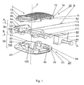
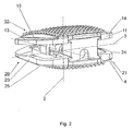
- an embodiment of the inventive intervertebral implant 1 which has an upper part 10 with an upper, arranged transversely to the central axis 2 Appositions Solution 15 for abutment with the base plate of an adjacent vertebral body, a lower part 20 with a lower, transverse to the central axis 2 arranged Appositions Product 25 Attachment to the cover plate of the adjacent vertebral body and two joints 38, 39 includes.
- the upper part 10 and the lower part 20 are connected movably relative to each other via the hinges 38, 39, wherein the mobility of the upper part 10 relative to the lower part 20 about a first, arranged transversely to the central axis 2 axis of rotation 3 within an angular range of +10 Is limited to -6 ° and is limited to a second, transverse to the central axis 2 and perpendicular to the first axis of rotation 3 arranged rotation axis 4 within an angular range of ⁇ 7 °.
- the joints 38, 39 are realized by three joint parts 31, 32, 33, of which the lower joint part 33 and the upper joint part 31 each form a joint 38, 39 cooperating with the middle joint part 32.
- the two joints 38, 39 are configured as rockers and each have an axis of rotation 3, 4, the axes of rotation being perpendicular to one another and perpendicular to the central axis 2.
- the lower hinge 39 comprises an elevation 50 forming the lower articulated part 33 and connected to the lower part 20, and a recess 52 accommodating the elevation 50 in the middle articulated part 32.
- the elevation is configured with an edge 51 forming the axis of rotation 4 the depression 52 is mounted such that the two joint parts 32, 33 form a joint 39 that can be tilted about the rotation axis 4 on the edge 51.
- the upper joint 38 is composed of a arranged on the upper hinge part 31 parallel to the axis of rotation 3 survey 49 and arranged on the middle hinge part 32, the collection 49 receiving recess 54 together.
- the elevation 49 is configured with an edge 53 forming the axis of rotation 3, which is mounted in the depression 54 such that the two joint parts 31, 32 form a joint 38 which can be tilted about the axis of rotation 3 on the edge 53.
- the mobility of the two parts 10, 20 relative to one another can be releasably blocked by the means 40.
- the means 40 in the embodiment shown here comprise an insert 41 which can be inserted from the ventral side surfaces 11, 21 of the two parts 10, 20 transversely to the central axis 2 and parallel to the lateral side surfaces 13, 14, 23, 24 of the two parts 10, 20
- the insertion of the insert 41 takes place in two depressions 42, 43, which are designed as dovetail guides.
- the insert 41 is inserted from the ventral side surfaces 11, 21 of the two parts 10, 20 into the depressions 42, 43 designed as dovetail guides and fastened to the lower part 20 by means of a screw 44.
- the insert 41 is designed to be terminally complementary to the depressions 42, 43, so that the two parts 10, 20 are fixed relative to one another parallel to the central axis 2 when the insert 41 is inserted.
- first locking means 100 are mounted on the middle joint part 32, which can be brought into engagement with second locking means 105 on the lower joint part 33 and prevent the middle joint part 32 from being removed from the lower joint part 33 after fastening the fixing element 110 to the middle joint part 32.
- the fastening of the fixing element 110 is effected by means of screws 111, which are screwed into the threaded holes 112 next to the recess 52 in the middle hinge part 32.
- the first locking means 100 comprise recesses 101 on the middle hinge part 32, which can be brought into positive engagement with the lugs 106 of the second locking means 105. This prevents that the two joint parts 32, 33 can be separated from each other.
- hinges 120 (FIGS. FIGS. 5 and 6 ), whereby the two joint parts 31, 32 are held together parallel to the central axis 2, without the rotational movement of the two joint parts 31, 32 being restricted relative to one another about the first axis of rotation 3.
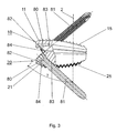
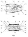
- FIG. 3 an embodiment of the inventive intervertebral implant 1 is shown, which differs from the in the Fig. 1 and 2 illustrated embodiment only in that the two parts 10, 20 comprise bores 80 for receiving bone fixation means 81, wherein the bone fixation means 80 are here designed as bone screws.
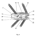
- the bores 80 have longitudinal axes 83, which enclose an angle ⁇ with the central axis 2. Further penetrate two holes 80 ( Fig. 4 ) one of the two parts 10, 20 from the ventral side surface 11, 21 to the apposition surface 15, 25.
- the longitudinal axes 83 of the bores 80 are viewed both laterally ( Fig. 3 ) as well as from the ventral view ( Fig. 4
- the bores 80 are conical, tapered against the Appositions vom 15, 25 and provided with internal threads 82, which serve for the screw-receiving the provided with complementary external screw heads 84 of bone screw designed as bone fixation 81.
- the hinges 120 allow a relative rotational movement of the two hinge parts 31, 32 about the first axis of rotation 3 formed by the edge 53 on the second elevation 49 and the recess 54 (FIGS. Fig. 2 ) and include on the middle hinge part 32 laterally terminally mounted cams 121, which are rounded against the ventral side surfaces 11, 21 of the intervertebral implant 1, and on the upper hinge part 31 mounted shells 122 which the rounded sides of the cams 121 from the ventral side surfaces 11, 21 encircle it at an angle of approx. 90 °. Through these shells 122, the upper joint part 31 is parallel to the central axis 2 (FIG. Fig. 1 ) held on the middle joint part 32.
Landscapes
- Health & Medical Sciences (AREA)
- Orthopedic Medicine & Surgery (AREA)
- Engineering & Computer Science (AREA)
- Biomedical Technology (AREA)
- Neurology (AREA)
- Life Sciences & Earth Sciences (AREA)
- Animal Behavior & Ethology (AREA)
- Veterinary Medicine (AREA)
- Heart & Thoracic Surgery (AREA)
- Public Health (AREA)
- General Health & Medical Sciences (AREA)
- Cardiology (AREA)
- Surgery (AREA)
- Oral & Maxillofacial Surgery (AREA)
- Transplantation (AREA)
- Vascular Medicine (AREA)
- Molecular Biology (AREA)
- Medical Informatics (AREA)
- Nuclear Medicine, Radiotherapy & Molecular Imaging (AREA)
- Prostheses (AREA)
Abstract
Description
- Die Erfindung bezieht sich auf ein Zwischenwirbelimplantat gemäss dem Oberbegriff des Patentanspruchs 1 und auf ein Verfahren zum Ersetzen einer defekten, natürlichen Bandscheibe durch ein Zwischenwirbelimplantat gemäss dem Patentanspruch 22.
- Nach Entfernung einer beschädigten, natürlichen Bandscheibe oder eines beschädigten Nukleus pulposus einer Bandscheibe werden Implantate oder Prothesen in den Zwischenwirbelraum zweier benachbarter Wirbelkörper eingebracht. Dabei entsteht das Ziel, wieder möglichst natürliche Zustände herbeizuführen, d.h. insbesondere die ursprüngliche Bandscheibenhöhe und damit den ursprünglichen Abstand zwischen den beiden benachbarten Wirbelkörpern wiederherzustellen. Ferner sollen Bewegungen der benachbarten Wirbelkörper relativ zueinander möglichst ohne Behinderung in ihrer natürlichen Art ausführbar sein. Hierzu ist die Erhaltung der Bewegungsmöglichkeiten bei einer Vorwärts/Rückwärtsneigung, d.h. Flexion und Extension der Wirbelkörper sowie bei einer lateralen Beugung der Wirbelkörper innerhalb der natürlichen Grenzen wesentlich. Die natürlichen Bänder und Muskeln entlang der Wirbelsäule werden im wesentlichen intakt gelassen, so dass diese die Bewegungen eines mechanischen Bandscheibenersatzes weiter stabilisieren.
- Ein Zwischenwirbelimplantat gemäß dem Oberbegriff des Anspruch 1 wird in der
WO 99/59492 DE-A 35 29 761 BÜTTNER bekannt. Diese bekannte Bandscheibenendoprothese besteht im wesentlichen aus zwei symmetrischen Abschlussplatten mit gegeneinander gerichteten konkaven Gleitflächen und je einer aussenstehenden Oberfläche zur Anlage an die Grundplatte, respektive die Deckplatte der angrenzenden Wirbelkörper und einem zwischen den Abschlussplatten positionierten Distanzstück mit zu den konkaven Gleitflächen an den Abschlussplatten komplementär ausgestalteten konvexen Gleitflächen. Die Gleitflächen sind in einer Ausführungsform als Teilflächen einer Zylindermantelfläche ausgebildet, wobei die an den beiden Abschlussplatten angeordneten Gleitflächen komplementär zu je einer der angrenzenden Gleitflächen am Distanzstück ausgestaltet sind und je zwei komplementäre Gleitflächen die aufeinander verschiebbaren Artikulationsflächen eines um eine Drehachse rotierbaren Gelenkteiles bilden. Das Gelenk umfasst ein oberes und ein unteres Gelenkteil mit je einer Drehachse. Die beiden Drehachsen sind um 90° zueinander versetzt. Nachteilig an dieser bekannten Bandscheibenendoprothese ist, dass - a) den durch die natürliche Bandscheibe übertragbaren überlagerten Schwenkbewegungen insbesondere bei anterior-posterior und lateraler Flexion, welche bei der natürlichen Bandscheibe unabhängig voneinander sind, durch die Ausgestaltung einer Bandscheibenendoprothese mit nur einem Drehzentrum nicht Rechnung getragen wird;
- b) durch Scherbewegungen, insbesondere bei Translation in anterior-posteriorer Richtung das Wirbelgelenk (Facettengelenk) belastet wird, wodurch für den Patienten Schmerzen verursacht werden können;
- c) nachteilige Reibungskräfte bei zwei aufeinander gleitbaren, artikulierenden Flächen entstehen. Ferner sind an den Flächen Verschleiss, d.h. unter anderem auch Abrieb sowie Widerstand bei der Bewegung der Gelenkteile die Folge. Zudem besteht das Risiko des "Stick-Slip" Effektes;
- d) ein mechanischer Bandscheibenersatz die weitere Degeneration der betroffenen Bewegungssegmente kaum aufhalten kann. Das Wiederherstellen der ursprünglichen Bewegungsverhältnisse reduziert den Schmerz wesentlich und der Patient gewinnt an Lebensqualität. Bei neuem Auftreten von Schmerz muss jedoch eine Revision der Versorgung in Angriff genommen werden. Dabei wird üblicherweise eine Bandscheibenprothese nach herkömmlicher Bauart komplett entfernt und das Bewegungssegment versteift. Diese Operation belastet den Patienten ausserordentlich; und
- e) der Form der Kontaktflächen zu den benachbarten Wirbelkörpern in der Regel nicht Rechnung getragen wird. Bandscheibenersatzimplantate herkömmlicher Bauart haben plane (flache) Kontaktflächen, welche oft noch mit kielartigen Erhebungen ergänzt sind.
- Hier will die Erfindung Abhilfe schaffen. Der Erfindung liegt die Aufgabe zugrunde, ein Zwischenwirbelimplantat zu schaffen, welches ein Gelenk umfasst, dessen Gelenkachsen Lagerungen mit einer minimalen Reibung aufweisen.
- Die Erfindung löst die gestellte Aufgabe mit einem Zwischenwirbelimplantat, welches die Merkmale des Anspruchs 1 aufweist und mit einem Verfahren zum Ersetzen einer defekten, natürlichen Bandscheibe durch ein Zwischenwirbelimplantat, welches die Schritte des Anspruchs 22 umfasst.
- Die durch die Erfindung erreichten Vorteile sind im wesentlichen darin zu sehen, dass dank des erfindungsgemässen Zwischenwirbelimplantates
- Die Schwenkbewegungen in anterior-posteriorer Richtung und nach lateral unabhängig sind;
- die Reibfläche der Bewegungen auf klingenähnlichen Mitteln auf ein Minimum reduziert ist; und
- durch die infolge des Linienkontaktes zwischen den Gelenkteilen anstelle von Gleitflächen geringere Reibungskräfte im Gelenk auftreten und daher Relativbewegungen der Wirbelkörper, insbesondere die laterale Beugung und Flexions- / Extensionsbewegungen der Wirbelsäule nicht behindert werden.
- Wegen der unterschiedlichen Positionen der natürlichen Drehachsen in den entlang der Wirbelsäule verschiedenen Bandscheibenräumen kann die Anordnung der Drehachsen windschief oder sich schneidend sein.
- Durch die Länge der Klingen ergibt sich eine Stabilisierung der Gelenke gegen eine Abdrehen der beiden Teile um die Zentralachse. Die Flankenwinkel der Erhebungen betragen vorzugsweise zwischen 1° und 30° während die Flankenwinkel der Vertiefungen vorzugsweise zwischen 6° und 70° betragen.
- In einer bevorzugten Ausführungsform des erfindungsgemässen Zwischenwirbelimplantates umfasst dieses zwei Gelenke mit je einem ersten und einem zweiten Gelenkteil, wobei das zweite Gelenkteil eine Vertiefung zur um die Drehachse kippbaren Aufnahme einer Erhebung am ersten Gelenkteil aufweist. Dadurch ist der Vorteil erreichbar, dass keine Translationsbewegung der an das Implantat angrenzenden Wirbelkörper zugelassen werden, wodurch die Facettengelenke geschont werden.
- In einer anderen Ausführungsform des erfindungsgemässen Zwischenwirbelimplantates sind von den ventralen Seitenflächen her Mittel an den beiden Teilen anbringbar, wodurch die beiden Teile ventral auf einer bestimmten Distanz relativ zueinander gehalten werden können. Dadurch ist der Vorteil erreichbar, dass die beiden Teile zur Einführung in den Zwischenwirbelraum in eine Position mit fest gehaltener Höhe bringbar sind und nach der Einführung in den Zwischenwirbelraum um das Gelenk bewegbar und an die Grund- respektive Deckplatte der angrenzenden Wirbelkörper zur Anlage bringbar sind.
- In einer weiteren Ausführungsform des erfindungsgemässen Zwischenwirbelimplantates ermöglichen die Mittel eine temporäre Blockierung der Beweglichkeit der beiden Teile um das Gelenk. Dadurch ist der Vorteil erreichbar, dass mittels eines minimal invasiven Eingriffes das im Zwischenwirbelraum integrierte Gelenk blockierbar ist. Dies ist besonders vorteilhaft in Fällen bei denen post-operativ Schmerzen auftreten, d.h. wo die Degeneration des betroffenen Wirbelsäulensegmentes weitergeht und der Chirurg eine Fusion der betroffenen Wirbel in Betracht zieht. Vorzugsweise sind die Mittel an den beiden ventralen Seitenflächen der beiden Teile anbringbar. Durch dieses spätere, sekundäre Blockieren der Bewegbarkeit der beiden Teile um das Gelenk wird das Zwischenwirbelimplantat versteift und in ein Arthrodesenimplantat (Fusions-Käfig) übergeführt.
- In wiederum einer weiteren Ausführungsform des erfindungsgemässen Zwischenwirbelimplantates umfassen die Mittel einen Einsatz, welche in je eine Vertiefung an den einander gegenüberliegenden Oberflächen des oberen und unteren Teiles einsetzbar ist. Vorzugsweise sind die Vertiefungen als Schwalbenschwanzführungen ausgestaltet, welche an den ventralen Seitenflächen offen sind, so dass die zu den Schwalbenschwanzführungen komplementär ausgestalteten Enden des Einsatzes von ventral in die Schwalbenschwanzführungen eingeschoben werden können. Dadurch ist der Vorteil erzielbar, dass durch das Einführen des Einsatzes die Bewegbarkeit der beiden Teile um das Gelenk blockierbar ist. Die Starrheit der Blockierung lässt sich erhöhen, wenn die Schwalbenschwanzführungen so ausgestaltet sind, dass sie sich gegen die Zentralachse des Zwischenwirbelimplantates verjüngen, so dass der Einsatz zusätzlich in den Schwalbenschwanzführungen verkeilbar ist.
- In wiederum einer anderen Ausführungsform des erfindungsgemässen Zwischenwirbelimplantates sind die beiden Teile mit Bohrungen zur Aufnahme von Knochenfixationsmittel, insbesondere von Knochenschrauben versehen, wobei die Bohrungen Längsachsen aufweisen, welche schräg zur Zentralachse stehen. Vorzugsweise durchdringen je zwei Bohrungen eines der beiden Teile von der ventralen Seitenfläche zur Appositionsfläche. Dabei können die Längsachsen, falls nur eine axiale Fixierung des Zwischenwirbelimplantates vorgesehen ist, nur von lateral betrachtet schräg zur Zentralachse stehen, oder falls eine winkelstabile Fixierung des Zwischenwirbelimplantates vorgesehen ist, auch von ventral betrachtet von den inneren Oberflächen der beiden Teile gegen die Appositionsflächen divergieren.
- In einer weiteren Ausführungsform des erfindungsgemässen Zwischenwirbelimplantates sind die Bohrungen zur Aufnahme der Knochenfixationsmittel mit Innengewinden versehen, wodurch sich eine zusätzliche, rigide Fixierung der Knochenfixationsmittel in den beiden Teilen erreichen lässt. Vorzugsweise sind die Bohrungen konisch ausgestaltet, so dass durch die konischen Gewindeverbindungen zwischen den Innengewinden und den Aussengewinden an den Köpfen der Knochenfixationsmittel eine verstärkte Fixierung der Knochenfixationsmittel an jedem der beiden Teile erreichbar ist.
- Die Appositionsflächen sind vorzugsweise konvex ausgestaltet und mit einer dreidimensionalen Strukturierung, vorzugsweise in Form von pyramidenförmigen Erhebungen versehen. Durch diese Ausgestaltung der Appositionsflächen wird der Anatomie der Wirbelkörperendplatten Rechnung getragen.
- Der Ersatz einer defekten, natürlichen Bandscheibe durch ein Zwischenwirbelimplantat umfasst die Schritte:
- A) blockieren des oder der Gelenke eines Zwischenwirbelimplantates mittels dafür vorgesehener Mittel in einer bestimmten Position des oder der Gelenke;
- B) einführen des Zwischenwirbelimplantates in den zu behandelnden Zwischenwirbelraum;
- C) lösen und entfernen der zur Blockierung des oder der Gelenke in das Zwischenwirbelimplantat eingesetzten Mittel. Durch die Blockierung des Gelenkes ist der Vorteil erreichbar, dass die beweglichen Teile mit den aussenstehenden Appositionsflächen einfacher in den zu behandelnden Zwischenwirbelraum einführbar sind.
- In einer weiteren Anwendung des Verfahren umfasst dieses das nachträgliche Blockieren des oder der Gelenke am implantierten Zwischenwirbelimplantat mittels der zur Blockierung des oder der Gelenke vorgesehenen Mittel. Dadurch ist der Vorteil erreichbar, dass bei einem Auftreten von post-operativen Schmerzen für den Patienten oder bei einer weiteren Degeneration des betroffenen Bewegungssegmentes das oder die Gelenke am Zwischenwirbelimplantat postoperativ durch Einsetzen der dazu vorgesehenen Mittel blockierbar sind. Diese nachträgliche Blockierung ist mit einem minimal-invasiven, vorzugsweise einem lapraskopischen Eingriff möglich. Das Zwischenwirbelimplantat übernimmt dann die Aufgabe eines Käfigs, so dass das betroffene Bewegungssegment der Wirbelsäule versteift werden kann.
- Die Erfindung und Weiterbildungen der Erfindung werden im folgenden anhand der teilweise schematischen Darstellungen mehrerer Ausführungsbeispiele noch näher erläutert.
- Es zeigen:
-
Fig. 1 eine Explosionsdarstellung einer Ausführungsform des erfindungsgemässen Zwischenwirbelimplantates; -
Fig. 2 eine perspektivische Ansicht der inFig. 1 dargestellten Ausführungsform des erfindungsgemässen Zwischenwirbelimplantates in zusammengesetztem Zustand; -
Fig. 3 eine Ansicht von lateral auf eine weitere Ausführungsform des erfindungsgemässen Zwischenwirbelimplantates; -
Fig. 4 eine perspektivische Ansicht von ventral der Ausführungsform nachFig. 3 ; -
Fig. 5 ein Schnitt längs der Linie A-A inFig. 1 mit Sicht von lateral; und -
Fig. 6 ein Schnitt längs der Linie B-B inFig. 1 mit Sicht von dorsal. - In den
Fig. 1 und2 ist eine Ausführungsform des erfindungsgemässen Zwischenwirbelimplantates 1 dargestellt, welche ein oberes Teil 10 mit einer oberen, quer zur Zentralachse 2 angeordneten Appositionsfläche 15 zur Anlage an die Grundplatte eines angrenzenden Wirbelkörpers, ein unteres Teil 20 mit einer unteren, quer zur Zentralachse 2 angeordneten Appositionsfläche 25 zur Anlage an die Deckplatte des angrenzenden Wirbelkörpers und zwei Gelenke 38;39 umfasst. Das obere Teil 10 und das untere Teil 20 sind über die Gelenke 38;39 relativ zueinander bewegbar verbunden, wobei die Bewegbarkeit des oberen Teils 10 relativ zum unteren Teil 20 um eine erste, quer zur Zentralachse 2 angeordnete Drehachse 3 innerhalb eines Winkelbereiches von +10° bis -6° eingeschränkt ist und um eine zweite, quer zur Zentralachse 2 und senkrecht zur ersten Drehachse 3 angeordneten Drehachse 4 innerhalb eines Winkelbereiches von ± 7° eingeschränkt ist. - Die Gelenke 38;39 sind durch drei Gelenkteile 31;32;33 realisiert, wovon das untere Gelenkteil 33 und das obere Gelenkteil 31 je ein mit dem mittleren Gelenkteil 32 zusammenwirkendes Gelenk 38;39 bilden. Die zwei Gelenke 38;39 sind als Wippen ausgestaltet und weisen je eine Drehachse 3;4 auf, wobei die Drehachsen senkrecht aufeinander und senkrecht zur Zentralachse 2 stehen. Das untere Gelenk 39 umfasst eine das untere Gelenkteil 33 bildende, mit dem unteren Teil 20 verbundene Erhebung 50 und eine im mittleren Gelenkteil 32 angeordnete, die Erhebung 50 aufnehmende Vertiefung 52. Die Erhebung ist mit einer die Drehachse 4 bildenden Kante 51 ausgestaltet, welche in der Vertiefung 52 derart gelagert ist, dass die beiden Gelenkteile 32;33 ein auf der Kante 51 um die Drehachse 4 kippbares Gelenk 39 bilden. Analog setzt sich das obere Gelenk 38 aus einer am oberen Gelenkteil 31 angeordneten zur Drehachse 3 parallelen Erhebung 49 und einer am mittleren Gelenkteil 32 angeordneten, die Erhebung 49 aufnehmenden Vertiefung 54 zusammen. Die Erhebung 49 ist mit einer die Drehachse 3 bildenden Kante 53 ausgestaltet, welche in der Vertiefung 54 derart gelagert ist, dass die beiden Gelenkteile 31;32 ein auf der Kante 53 um die Drehachse 3 kippbares Gelenk 38 bilden.
- Die Bewegbarkeit der beiden Teile 10;20 relativ zueinander ist durch die Mittel 40 lösbar blockierbar. Die Mittel 40 umfassen in der hier dargestellten Ausführungsform einen von den ventralen Seitenflächen 11;21 der beiden Teile 10;20 her quer zur Zentralachse 2 und parallel zu den lateralen Seitenflächen 13;14;23;24 der beiden Teile 10;20 einschiebbaren Einsatz 41. Das Einschieben des Einsatzes 41 erfolgt in zwei Vertiefungen 42;43, welche als Schwalbenschwanzführungen ausgestaltet sind. Der Einsatz 41 wird von den ventralen Seitenflächen 11;21 der beiden Teile 10;20 in die als Schwalbenschwanzführungen ausgestalteten Vertiefungen 42;43 eingeführt und am unteren Teil 20 mittels einer Schraube 44 befestigt. Zudem ist der Einsatz 41 endständig komplementär zu den Vertiefungen 42;43 ausgestaltet, so dass die beiden Teile 10;20 bei eingeschobenem Einsatz 41 parallel zur Zentralachse 2 relativ zueinander fixiert sind.
- Ferner sind am mittleren Gelenkteil 32 erste Arretiermittel 100 angebracht, welche mit zweiten Arretiermitteln 105 am unteren Gelenkteil 33 in Eingriff bringbar sind und nach dem Befestigen des Fixierelementes 110 am mittleren Gelenkteil 32 ein Entfernen des mittleren Gelenkteiles 32 vom unteren Gelenkteil 33 verhindern. Die Befestigung des Fixierelementes 110 erfolgt mittels Schrauben 111, welche in die Gewindelöcher 112 neben der Vertiefung 52 in das mittlere Gelenkteil 32 eingeschraubt werden. Die ersten Arretiermittel 100 umfassen Vertiefungen 101 am mittleren Gelenkteil 32, welche mit den Nasen 106 der zweiten Arretiermittel 105 formschlüssig in Eingriff bringbar sind. Dadurch wird verhindert, dass die beiden Gelenkteile 32;33 voneinander getrennt werden können. Zwischen dem oberen Gelenkteil 31 und dem mittleren Gelenkteil 32 sind ferner Scharniere 120 (
Fig. 5 und 6 ) angeordnet, wodurch die beiden Gelenkteile 31;32 parallel zur Zentralachse 2 zusammengehalten werden, ohne dass die Rotationsbewegung der beiden Gelenkteile 31;32 relativ zueinander um die erste Drehachse 3 dadurch eingeschränkt wird. - In
Fig. 3 ist eine Ausführungsform des erfindungsgemässen Zwischenwirbelimplantates 1 dargestellt, welche sich von der in denFig. 1 und2 dargestellten Ausführungsform nur darin unterscheidet, dass die beiden Teilen 10;20 Bohrungen 80 zur Aufnahme von Knochenfixationsmitteln 81 umfassen, wobei die Knochenfixationsmittel 80 hier als Knochenschrauben ausgestaltet sind. Die Bohrungen 80 weisen Längsachsen 83 auf, welche einen Winkel γ mit der Zentralachse 2 einschliessen. Ferner durchdringen je zwei Bohrungen 80 (Fig. 4 ) eines der beiden Teile 10;20 von der ventralen Seitenfläche 11;21 zur Appositionsfläche 15;25. Die Längsachsen 83 der Bohrungen 80 stehen sowohl von lateral betrachtet (Fig. 3 ) als auch von ventral betrachtet (Fig. 4 ) schräg zur Zentralachse 2. Ferner sind die Bohrungen 80 konisch, sich gegen die Appositionsflächen 15;25 verjüngend ausgestaltet und mit Innengewinden 82 versehen, welche zur schraubbaren Aufnahme der mit komplementären Aussengewinden versehenen Schraubenköpfe 84 der als Knochenschrauben ausgestalteten Knochenfixationsmittel 81 dienen. - In den
Fig. 5 und 6 sind die beiden Scharniere 120 zwischen dem oberen Gelenkteil 31 und dem mittleren Gelenkteil 32 ausführlicher dargestellt. Die Scharniere 120 gestatten eine relative Drehbewegung der beiden Gelenkteile 31;32 um die durch die Kante 53 an der zweiten Erhebung 49 und der Vertiefung 54 gebildete, erste Drehachse 3 (Fig. 2 ) und umfassen am mittleren Gelenkteil 32 lateral endständig angebrachte Nocken 121, welche gegen die ventralen Seitenflächen 11;21 des Zwischenwirbelimplantates 1 abgerundet sind, und am oberen Gelenkteil 31 angebrachte Schalen 122, welche die abgerundeten Seiten der Nocken 121 von den ventralen Seitenflächen 11;21 her kreisbogenförmig mit einem Winkel von ca. 90° umschliessen. Durch diese Schalen 122 wird das obere Gelenkteil 31 parallel zur Zentralachse 2 (Fig. 1 ) am mittleren Gelenkteil 32 festgehalten.
Claims (21)
- Zwischenwirbelimplantat (1), insbesondere künstliche Bandscheibe, mit einer Zentralachse (2), einem oberen Teil (10), das für die Anlage an die Grundplatte eines darüber liegenden Wirbelkörpers geeignet ist und einem unteren Teil (20), das für die Anlage an die Deckplatte eines darunter liegenden Wirbelkörpers geeignet ist, wobeiA) das obere Teil (10) eine ventrale Seitenfläche (11), eine dorsale Seitenfläche (12), zwei laterale Seitenflächen (13,14), eine obere Appositionsfläche (15) und eine untere Oberfläche (16) aufweist;B) das untere Teil (20) eine ventrale Seitenfläche (21), eine dorsale Seitenfläche (22), zwei laterale Seitenflächen (23,24), eine untere Appositionsfläche (25) und eine obere Oberfläche (26) aufweist;C) die beiden Teile (10,20) durch zwei zwischen den beiden Teilen (10;20) angeordnete Gelenke (38;39) relativ zueinander bewegbar sind, wobeiD) jedes der Gelenke (38;39) eine Drehachse (3;4) aufweist und die beiden Drehachsen (3;4) quer zueinander angeordnet sind; undE) die beiden Gelenke (38;39) durch ein mit dem oberen Teil (10) verbundenes, oberes Gelenkteil (31), ein mittleres Gelenkteil (32) und ein mit dem unteren Teil (20) verbundenes, unteres Gelenkteil (33) realisiert sind,
dadurch gekennzeichnet, dassF) jedes Gelenk (38;39) ein erstes Gelenkteil (31;32;33) mit einer eine Kante (51;53) aufweisenden Erhebung (49;50) zur um die Drehachse (3;4) kippbaren Lagerung eines zweiten Gelenkteiles (31;32;33) umfasst. - Zwischenwirbelimplantat (1) nach Anspruch 1, dadurch gekennzeichnet, dass das untere Gelenkteil (33) eine die Kante (51) aufweisende Erhebung (50) zur um die Drehachse (4) kippbaren Lagerung des mittleren Gelenkteiles (31;32) umfasst.
- Zwischenwirbelimplantat (1) nach Anspruch 1 oder 2, dadurch gekennzeichnet, dass das obere Gelenkteil (33) eine die Kante (53) aufweisende Erhebung (49) zur um die Drehachse (3) kippbaren Lagerung des mittleren Gelenkteiles (32) umfasst.
- Zwischenwirbelimplantat (1) nach einem der Ansprüche 1 bis 3, dadurch gekennzeichnet, dass das zweite Gelenkteil (31;32;33) eine Vertiefung (52;54) zur Aufnahme der Erhebung (49;50) am ersten Gelenkteil (31;32;33) umfasst.
- Zwischenwirbelimplantat (1) nach Anspruch 4, dadurch gekennzeichnet, dass das untere Gelenkteil (33) eine zur Drehachse (4) parallele Erhebung (50) mit einer die Drehachse (4) bildenden Kante (51) umfasst und die Erhebung (50) in der Vertiefung (52) am mittleren Gelenkteil (32) gelagert ist.
- Zwischenwirbelimplantat (1) nach Anspruch 4 oder 5, dadurch gekennzeichnet, dass das obere Gelenkteil (31) eine zur Drehachse (3) parallele Erhebung (49) mit einer die Drehachse (3) bildenden Kante (53) umfasst und die Erhebung (49) in einer Vertiefung (54) am mittleren Gelenkteil (32) gelagert ist.
- Zwischenwirbelimplantat (1) nach einem der Ansprüche 1 bis 6, dadurch gekennzeichnet, dass die Drehachsen (3;4) windschief zueinander stehen.
- Zwischenwirbelimplantat (1) nach einem der Ansprüche 1 bis 7, dadurch gekennzeichnet, dass Mittel (40) vorgesehen sind, welche die beiden Teile (10;20), bei ihren ventralen Seitenflächen (11;21) gemessen, auf einer festen Distanz voneinander halten.
- Zwischenwirbelimplantat (1) nach einem der Ansprüche 1 bis 7, dadurch gekennzeichnet, dass Mittel (40) vorgesehen sind, welche geeignet sind eine temporäre Blockierung der Beweglichkeit der beiden Teile (10,20) um die Gelenke (38;39) herbeizuführen.
- Zwischenwirbelimplantat (1) nach Anspruch 8 oder 9, dadurch gekennzeichnet, dass die Mittel (40) an den beiden ventralen Seitenflächen (11,21) an den beiden Teilen (10;20) anbringbar sind.
- Zwischenwirbelimplantat (1) nach Anspruch 9 oder 10, dadurch gekennzeichnet, dass die Mittel (40) einen Einsatz (41) mit einem unteren Ende (45) und einem oberen Ende (46) und an den beiden Teilen (10;20) je eine Vertiefung (42;43) in den Oberflächen (16;26) umfassen, welche an den ventralen Seitenflächen (11;21) offen sind, und dass der Einsatz (41) mit seinen Enden (45;46) in je eine Vertiefung (42;43) einfügbar ist.
- Zwischenwirbelimplantat (1) nach Anspruch 11, dadurch gekennzeichnet, dass die Vertiefungen (42;43) Schwalbenschwanzführungen sind und die Enden (45;46) am Einsatz (41) komplementär zu diesen Schwalbenschwanzführungen ausgestaltet sind.
- Zwischenwirbelimplantat (1) nach Anspruch 12, dadurch gekennzeichnet, dass sich die Schwalbenschwanzführungen von den ventralen Seitenflächen (11;21) her gegen die dorsalen Seitenflächen (12;22) verjüngen.
- Zwischenwirbelimplantat (1) nach einem der Ansprüche 1 bis 13, dadurch gekennzeichnet, dass das obere und das untere Teil (10;20) je mindestens zwei von den ventralen Seitenflächen (11;21) zu den Appositionsflächen (15;25) durchgehende Bohrungen (80) mit Längsachsen (83) zur Aufnahme von Knochenfixationsmitteln (81) umfassen.
- Zwischenwirbelimplantat (1) nach Anspruch 14, dadurch gekennzeichnet, dass die Längsachsen (83) der Bohrungen (80) mit der Zentralachse (2) einen Winkel γ einschliessen.
- Zwischenwirbelimplantat (1) nach Anspruch 15, dadurch gekennzeichnet, dass der Winkel γ in einem Bereich von 20° und 65° liegt.
- Zwischenwirbelimplantat (1) nach einem der Ansprüche 14 bis 16, dadurch gekennzeichnet, dass die Längsachsen (83) der Bohrungen (80) von den ventralen Seitenflächen (11;21) aus betrachtet von den inneren Oberflächen (16;26) gegen die Appositionsflächen (15;25) divergieren.
- Zwischenwirbelimplantat (1) nach einem der Ansprüche 14 bis 17, dadurch gekennzeichnet, dass sich die Bohrungen (80) gegen die Appositionsflächen (15;25) konisch verjüngen.
- Zwischenwirbelimplantat (1) nach einem der Ansprüche 14 bis 18, dadurch gekennzeichnet, dass die Bohrungen (80) ein Innengewinde (82) aufweisen.
- Zwischenwirbelimplantat (1) nach einem der Ansprüche 1 bis 19, dadurch gekennzeichnet, dass das mittlere Gelenkteil (32) erste Arretiermittel (100) und das untere Gelenkteil (33) zweite Arretiermittel (105) umfasst, und dass die ersten und zweiten Arretiermittel (100;105) miteinander in Eingriff bringbar sind.
- Zwischenwirbelimplantat (1) nach einem der Ansprüche 1 bis 20, dadurch gekennzeichnet, dass zwischen dem oberen Gelenkteil (31) und dem mittleren Gelenkteil (32) Scharniere (120) angebracht sind, wodurch die beiden Gelenkteile (31;32) parallel zur Zentralachse (2) zusammengehalten werden, ohne dass die Rotationsbewegung der beiden Gelenkteile (31;32) relativ zueinander um die erste Drehachse (3) dadurch eingeschränkt wird.
Applications Claiming Priority (1)
| Application Number | Priority Date | Filing Date | Title |
|---|---|---|---|
| PCT/CH2002/000705 WO2004054476A1 (de) | 2002-12-17 | 2002-12-17 | Zwischenwirbelimplantat mit kippbaren gelenkteilen |
Publications (2)
| Publication Number | Publication Date |
|---|---|
| EP1572037A1 EP1572037A1 (de) | 2005-09-14 |
| EP1572037B1 true EP1572037B1 (de) | 2008-05-07 |
Family
ID=32514198
Family Applications (1)
| Application Number | Title | Priority Date | Filing Date |
|---|---|---|---|
| EP02782616A Expired - Lifetime EP1572037B1 (de) | 2002-12-17 | 2002-12-17 | Zwischenwirbelimplantat mit kippbaren gelenkteilen |
Country Status (15)
| Country | Link |
|---|---|
| US (1) | US8388686B2 (de) |
| EP (1) | EP1572037B1 (de) |
| JP (1) | JP4210652B2 (de) |
| KR (1) | KR101004374B1 (de) |
| CN (1) | CN100400015C (de) |
| AR (1) | AR042504A1 (de) |
| AT (1) | ATE394085T1 (de) |
| AU (1) | AU2002347117B2 (de) |
| BR (1) | BR0215969A (de) |
| CA (1) | CA2510244C (de) |
| DE (1) | DE50212249D1 (de) |
| ES (1) | ES2306798T3 (de) |
| HU (1) | HUP0500746A2 (de) |
| TW (1) | TW200422031A (de) |
| WO (1) | WO2004054476A1 (de) |
Cited By (1)
| Publication number | Priority date | Publication date | Assignee | Title |
|---|---|---|---|---|
| US8715352B2 (en) | 2006-12-14 | 2014-05-06 | Depuy Spine, Inc. | Buckling disc replacement |
Families Citing this family (69)
| Publication number | Priority date | Publication date | Assignee | Title |
|---|---|---|---|---|
| FR2897259B1 (fr) | 2006-02-15 | 2008-05-09 | Ldr Medical Soc Par Actions Si | Cage intersomatique transforaminale a greffon de fusion intervetebrale et instrument d'implantation de la cage |
| FR2824261B1 (fr) | 2001-05-04 | 2004-05-28 | Ldr Medical | Prothese de disque intervertebral et procede et outils de mise en place |
| FR2827156B1 (fr) | 2001-07-13 | 2003-11-14 | Ldr Medical | Dispositif de cage vertebrale avec fixation modulaire |
| FR2846550B1 (fr) | 2002-11-05 | 2006-01-13 | Ldr Medical | Prothese de disque intervertebral |
| DE10330699B3 (de) | 2003-07-08 | 2005-02-17 | Aesculap Ag & Co. Kg | Chirurgisches Instrument zum Handhaben eines Implantats |
| DE10330698B4 (de) | 2003-07-08 | 2005-05-25 | Aesculap Ag & Co. Kg | Zwischenwirbelimplantat |
| DE20313183U1 (de) | 2003-08-22 | 2003-10-16 | Aesculap Ag & Co Kg | Zwischenwirbelimplantat |
| EP1532950B1 (de) | 2003-11-18 | 2008-03-26 | Zimmer GmbH | Bandscheibenimplantat |
| ES2547532T3 (es) | 2004-02-04 | 2015-10-07 | Ldr Medical | Prótesis de disco intervertebral |
| FR2865629B1 (fr) | 2004-02-04 | 2007-01-26 | Ldr Medical | Prothese de disque intervertebral |
| AU2005216112B2 (en) * | 2004-02-20 | 2010-07-08 | Spinecore, Inc. | Artificial intervertebral disc having a universal joint |
| FR2869528B1 (fr) | 2004-04-28 | 2007-02-02 | Ldr Medical | Prothese de disque intervertebral |
| DE102004028967B4 (de) | 2004-06-16 | 2006-05-24 | Aesculap Ag & Co. Kg | Zwischenwirbelimplantat |
| FR2879436B1 (fr) | 2004-12-22 | 2007-03-09 | Ldr Medical | Prothese de disque intervertebral |
| US8696707B2 (en) | 2005-03-08 | 2014-04-15 | Zyga Technology, Inc. | Facet joint stabilization |
| US9744052B2 (en) | 2005-04-12 | 2017-08-29 | Nathan C. Moskowitz | Bi-directional fixating/locking transvertebral body screw/intervertebral cage stand-alone constructs |
| US9814601B2 (en) | 2005-04-12 | 2017-11-14 | Nathan C. Moskowitz | Bi-directional fixating/locking transvertebral body screw/intervertebral cage stand-alone constructs |
| US11903849B2 (en) | 2005-04-12 | 2024-02-20 | Moskowitz Family Llc | Intervertebral implant and tool assembly |
| US7942903B2 (en) | 2005-04-12 | 2011-05-17 | Moskowitz Ahmnon D | Bi-directional fixating transvertebral body screws and posterior cervical and lumbar interarticulating joint calibrated stapling devices for spinal fusion |
| US9848993B2 (en) | 2005-04-12 | 2017-12-26 | Nathan C. Moskowitz | Zero-profile expandable intervertebral spacer devices for distraction and spinal fusion and a universal tool for their placement and expansion |
| US9532821B2 (en) | 2005-04-12 | 2017-01-03 | Nathan C. Moskowitz | Bi-directional fixating/locking transvertebral body screw/intervertebral cage stand-alone constructs with vertical hemi-bracket screw locking mechanism |
| US7846188B2 (en) | 2005-04-12 | 2010-12-07 | Moskowitz Nathan C | Bi-directional fixating transvertebral body screws, zero-profile horizontal intervertebral miniplates, total intervertebral body fusion devices, and posterior motion-calibrating interarticulating joint stapling device for spinal fusion |
| GB0516034D0 (en) | 2005-08-04 | 2005-09-14 | Blacklock T | Orthopaedic medical device |
| FR2891135B1 (fr) | 2005-09-23 | 2008-09-12 | Ldr Medical Sarl | Prothese de disque intervertebral |
| FR2893838B1 (fr) | 2005-11-30 | 2008-08-08 | Ldr Medical Soc Par Actions Si | Prothese de disque intervertebral et instrumentation d'insertion de la prothese entre les vertebres |
| US8465546B2 (en) | 2007-02-16 | 2013-06-18 | Ldr Medical | Intervertebral disc prosthesis insertion assemblies |
| FR2916956B1 (fr) | 2007-06-08 | 2012-12-14 | Ldr Medical | Cage intersomatique,prothese intervertebrale,dispositif d'ancrage et instrumentation d'implantation |
| US12539219B2 (en) | 2007-08-21 | 2026-02-03 | Moskowitz Family Llc | Intervertebral implant and tool assembly |
| US8343189B2 (en) * | 2007-09-25 | 2013-01-01 | Zyga Technology, Inc. | Method and apparatus for facet joint stabilization |
| US8728165B2 (en) * | 2007-11-12 | 2014-05-20 | Centinel Spine, Inc. | Orthopaedic implants and protheses |
| US8323292B2 (en) * | 2008-12-15 | 2012-12-04 | Spinecore, Inc. | Adjustable pin drill guide and methods therefor |
| WO2010070444A1 (fr) * | 2008-12-18 | 2010-06-24 | Medtech Research Sa | Système de stabilisation intervertébrale articulé |
| JP5492906B2 (ja) * | 2008-12-18 | 2014-05-14 | ラマン,ジョン,アール | キーレスカップリングアレンジメント |
| WO2010135405A1 (en) * | 2009-05-19 | 2010-11-25 | Synthes Usa, Llc | Dynamic trial implants |
| US8394125B2 (en) | 2009-07-24 | 2013-03-12 | Zyga Technology, Inc. | Systems and methods for facet joint treatment |
| EP3011934B1 (de) | 2009-09-17 | 2017-12-13 | LDR Holding Corporation | Zwischenwirbelimplantat mit expandierbaren knochenfixierelementen |
| US8709086B2 (en) | 2009-10-15 | 2014-04-29 | Globus Medical, Inc. | Expandable fusion device and method of installation thereof |
| BR112012016296A2 (pt) | 2009-12-31 | 2017-03-21 | Ldr Medical | dispositivo de ancoragem, implante intervertebral e instrumento de implantação |
| US8795366B2 (en) * | 2010-01-11 | 2014-08-05 | Innova Spinal Technologies, Llc | Expandable intervertebral implant and associated surgical method |
| US9233006B2 (en) | 2010-06-15 | 2016-01-12 | Zyga Technology, Inc. | Systems and methods for facet joint treatment |
| US8663293B2 (en) | 2010-06-15 | 2014-03-04 | Zyga Technology, Inc. | Systems and methods for facet joint treatment |
| US9474625B2 (en) | 2010-09-03 | 2016-10-25 | Globus Medical, Inc | Expandable fusion device and method of installation thereof |
| FR2987256B1 (fr) | 2012-02-24 | 2014-08-08 | Ldr Medical | Dispositif d'ancrage pour implant intervertebral, implant intervertebral et instrumentation d'implantation |
| US9072606B2 (en) | 2012-07-17 | 2015-07-07 | Clemson University Research Foundation | Lockable knee implants and related methods |
| US12491088B2 (en) | 2012-10-25 | 2025-12-09 | Moskowitz Family Llc | Expandable spinal spacer device |
| WO2014078541A1 (en) | 2012-11-15 | 2014-05-22 | Zyga Technology, Inc. | Systems and methods for facet joint treatment |
| US12193948B2 (en) | 2013-03-13 | 2025-01-14 | Life Spine, Inc. | Expandable implant assembly |
| US10426632B2 (en) | 2013-03-13 | 2019-10-01 | Life Spine, Inc. | Expandable spinal interbody assembly |
| FR3005569B1 (fr) | 2013-05-16 | 2021-09-03 | Ldr Medical | Implant vertebral, dispositif de fixation vertebrale d'implant et instrumentation d'implantation |
| FR3016793B1 (fr) | 2014-01-30 | 2021-05-07 | Ldr Medical | Dispositif d'ancrage pour implant spinal, implant spinal et instrumentation d'implantation |
| US9839528B2 (en) | 2014-02-07 | 2017-12-12 | Globus Medical, Inc. | Variable lordosis spacer and related methods of use |
| FR3020756B1 (fr) | 2014-05-06 | 2022-03-11 | Ldr Medical | Implant vertebral, dispositif de fixation vertebrale d'implant et instrumentation d'implantation |
| US11896494B2 (en) | 2017-07-10 | 2024-02-13 | Life Spine, Inc. | Expandable implant assembly |
| CN107693169A (zh) * | 2017-09-16 | 2018-02-16 | 武汉光谷北宸医疗器械有限公司 | 楔入式可调节人工椎体 |
| GB201902002D0 (en) | 2019-02-13 | 2019-04-03 | Axis Spine Tech Ltd | Intervertebral devices |
| GB201818847D0 (en) | 2018-11-19 | 2019-01-02 | Axis Spine Tech Ltd | Intervertebral devices |
| GB201818850D0 (en) | 2018-11-19 | 2019-01-02 | Axis Spine Tech Ltd | Intervertebral devices |
| GB201818849D0 (en) | 2018-11-19 | 2019-01-02 | Axis Spine Tech Ltd | Intervertebral devices |
| EP3979951A1 (de) | 2019-06-10 | 2022-04-13 | Life Spine, Inc. | Expandierbare implantatanordnung mit kompressionsmerkmalen |
| US12042395B2 (en) | 2019-06-11 | 2024-07-23 | Life Spine, Inc. | Expandable implant assembly |
| GB201910640D0 (en) | 2019-07-25 | 2019-09-11 | Axis Spine Tech Ltd | Insertions instruments |
| GB201910668D0 (en) | 2019-07-25 | 2019-09-11 | Axis Spine Tech Ltd | Assemblies for and methods of determing height and angle of an intervertebral device |
| KR102147077B1 (ko) * | 2019-10-07 | 2020-08-24 | (주)엘앤케이바이오메드 | 높이조절이 가능한 척추 유합 케이지 |
| US11857432B2 (en) | 2020-04-13 | 2024-01-02 | Life Spine, Inc. | Expandable implant assembly |
| US11602439B2 (en) | 2020-04-16 | 2023-03-14 | Life Spine, Inc. | Expandable implant assembly |
| US12336917B2 (en) | 2020-05-15 | 2025-06-24 | Life Spine, Inc. | Steerable implant assembly |
| US11602440B2 (en) | 2020-06-25 | 2023-03-14 | Life Spine, Inc. | Expandable implant assembly |
| US11554020B2 (en) | 2020-09-08 | 2023-01-17 | Life Spine, Inc. | Expandable implant with pivoting control assembly |
| CN114176747B (zh) * | 2020-09-15 | 2024-03-08 | 北京纳通医学科技研究院有限公司 | 寰枢椎关节融合器 |
Family Cites Families (14)
| Publication number | Priority date | Publication date | Assignee | Title |
|---|---|---|---|---|
| ATE44871T1 (de) * | 1984-09-04 | 1989-08-15 | Univ Berlin Humboldt | Bandscheibenendoprothese. |
| CA1283501C (en) * | 1987-02-12 | 1991-04-30 | Thomas P. Hedman | Artificial spinal disc |
| US5593447A (en) * | 1995-08-25 | 1997-01-14 | Angeli; Jose A. | Minimal contact prosthesis |
| US5893889A (en) * | 1997-06-20 | 1999-04-13 | Harrington; Michael | Artificial disc |
| US6179874B1 (en) * | 1998-04-23 | 2001-01-30 | Cauthen Research Group, Inc. | Articulating spinal implant |
| US6019792A (en) * | 1998-04-23 | 2000-02-01 | Cauthen Research Group, Inc. | Articulating spinal implant |
| WO1999059492A1 (de) | 1998-05-19 | 1999-11-25 | Synthes Ag Chur | Osteosynthetisches implantat mit eingelassener gelenkverbindung |
| EP1645248B8 (de) * | 2000-02-04 | 2010-06-16 | Warsaw Orthopedic, Inc. | Ausdehnbares interspinales Fusionsimplantat mit schwenkbarem Blocker |
| WO2001064142A1 (en) * | 2000-02-28 | 2001-09-07 | Sdgi Holdings, Inc. | Articulating spinal implant |
| US6610093B1 (en) * | 2000-07-28 | 2003-08-26 | Perumala Corporation | Method and apparatus for stabilizing adjacent vertebrae |
| FR2824261B1 (fr) * | 2001-05-04 | 2004-05-28 | Ldr Medical | Prothese de disque intervertebral et procede et outils de mise en place |
| US7179294B2 (en) * | 2002-04-25 | 2007-02-20 | Warsaw Orthopedic, Inc. | Articular disc prosthesis and method for implanting the same |
| US7273496B2 (en) * | 2002-10-29 | 2007-09-25 | St. Francis Medical Technologies, Inc. | Artificial vertebral disk replacement implant with crossbar spacer and method |
| EP1567098B1 (de) * | 2002-10-31 | 2012-08-29 | Zimmer Spine, Inc. | Bewegliches bandscheibenimplantat |
-
2002
- 2002-12-17 US US10/539,660 patent/US8388686B2/en not_active Expired - Fee Related
- 2002-12-17 ES ES02782616T patent/ES2306798T3/es not_active Expired - Lifetime
- 2002-12-17 BR BR0215969-4A patent/BR0215969A/pt not_active IP Right Cessation
- 2002-12-17 CN CNB028300610A patent/CN100400015C/zh not_active Expired - Fee Related
- 2002-12-17 JP JP2004559544A patent/JP4210652B2/ja not_active Expired - Fee Related
- 2002-12-17 DE DE50212249T patent/DE50212249D1/de not_active Expired - Lifetime
- 2002-12-17 HU HU0500746A patent/HUP0500746A2/hu unknown
- 2002-12-17 CA CA2510244A patent/CA2510244C/en not_active Expired - Fee Related
- 2002-12-17 WO PCT/CH2002/000705 patent/WO2004054476A1/de not_active Ceased
- 2002-12-17 AU AU2002347117A patent/AU2002347117B2/en not_active Ceased
- 2002-12-17 EP EP02782616A patent/EP1572037B1/de not_active Expired - Lifetime
- 2002-12-17 KR KR1020057011461A patent/KR101004374B1/ko not_active Expired - Fee Related
- 2002-12-17 AT AT02782616T patent/ATE394085T1/de not_active IP Right Cessation
-
2003
- 2003-11-28 TW TW092133515A patent/TW200422031A/zh not_active IP Right Cessation
- 2003-12-17 AR ARP030104676A patent/AR042504A1/es unknown
Cited By (1)
| Publication number | Priority date | Publication date | Assignee | Title |
|---|---|---|---|---|
| US8715352B2 (en) | 2006-12-14 | 2014-05-06 | Depuy Spine, Inc. | Buckling disc replacement |
Also Published As
| Publication number | Publication date |
|---|---|
| JP4210652B2 (ja) | 2009-01-21 |
| CN100400015C (zh) | 2008-07-09 |
| EP1572037A1 (de) | 2005-09-14 |
| HUP0500746A2 (en) | 2006-04-28 |
| CA2510244C (en) | 2011-03-22 |
| ATE394085T1 (de) | 2008-05-15 |
| WO2004054476A1 (de) | 2004-07-01 |
| AR042504A1 (es) | 2005-06-22 |
| JP2006509561A (ja) | 2006-03-23 |
| TW200422031A (en) | 2004-11-01 |
| AU2002347117B2 (en) | 2006-10-26 |
| CN1713867A (zh) | 2005-12-28 |
| KR101004374B1 (ko) | 2010-12-27 |
| AU2002347117A1 (en) | 2004-07-09 |
| TWI303168B (de) | 2008-11-21 |
| BR0215969A (pt) | 2005-09-27 |
| US20070276498A1 (en) | 2007-11-29 |
| ES2306798T3 (es) | 2008-11-16 |
| CA2510244A1 (en) | 2004-07-01 |
| DE50212249D1 (de) | 2008-06-19 |
| KR20050092720A (ko) | 2005-09-22 |
| US8388686B2 (en) | 2013-03-05 |
Similar Documents
| Publication | Publication Date | Title |
|---|---|---|
| EP1572037B1 (de) | Zwischenwirbelimplantat mit kippbaren gelenkteilen | |
| EP1575457B1 (de) | Zwischenwirbelimplantat | |
| EP1572038B1 (de) | Zwischenwirbelimplantat mit kardanisch gelagerten gelenkteilen | |
| EP1572036B1 (de) | Zwischenwirbelimplantat mit auf wälzkörpern gelagerten gelenkteilen | |
| EP1572039B1 (de) | Zwischenwirbelimplantat | |
| EP1648351B1 (de) | Zwischenwirbelimplantat mit temporären blockiermitteln | |
| EP1646336B1 (de) | Zwischenwirbelimplantat mit kalottenartigen gelenkflächen | |
| DE69936263T2 (de) | Geschraubte zylindrische, multidiskoide einfach- oder mehrfach-netzwerkplattenprothese | |
| EP1539051B1 (de) | Implantat mit zweiteiligem gelenk | |
| EP1534193B1 (de) | Zwischenwirbelimplantat mit dreiteiligem gelenk | |
| EP1959871B1 (de) | Facettengelenkprothese | |
| DE60302595T2 (de) | Wirbelzwischenstück mit schwenkbaren Endplatten | |
| EP0680292B1 (de) | System für die ausbildung einer kniegelenk-endoprothese | |
| DE10333659A1 (de) | Wirbelsäulenimplantat | |
| EP0519873A2 (de) | Gelenkprothese, insbesondere Kniegelenkprothese | |
| DE2908898A1 (de) | Prothesengelenk | |
| DE10323363A1 (de) | Implantat zum Einsetzen zwischen Wirbelkörper der Wirbelsäule | |
| DE102015101675B4 (de) | Implantat | |
| DE202004015198U1 (de) | Implantatsystem | |
| EP1848379A1 (de) | Zwischenwirbelimplantat | |
| EP1411870A1 (de) | Endoprothese für ein kniegelenk | |
| DE29514169U1 (de) | Prothese für den Ersatz eines Gelenks | |
| DE20302180U1 (de) | Implantat | |
| DE102004047566B3 (de) | Implantatsystem | |
| DE102021127834A1 (de) | Tibiakomponente und Kniegelenkendoprothesensystem |
Legal Events
| Date | Code | Title | Description |
|---|---|---|---|
| PUAI | Public reference made under article 153(3) epc to a published international application that has entered the european phase |
Free format text: ORIGINAL CODE: 0009012 |
|
| 17P | Request for examination filed |
Effective date: 20050511 |
|
| AK | Designated contracting states |
Kind code of ref document: A1 Designated state(s): AT BE BG CH CY CZ DE DK EE ES FI FR GB GR IE IT LI LU MC NL PT SE SI SK TR |
|
| AX | Request for extension of the european patent |
Extension state: AL LT LV MK RO |
|
| RAP1 | Party data changed (applicant data changed or rights of an application transferred) |
Owner name: SYNTHES GMBH |
|
| RAP1 | Party data changed (applicant data changed or rights of an application transferred) |
Owner name: SYNTHES GMBH |
|
| DAX | Request for extension of the european patent (deleted) | ||
| GRAP | Despatch of communication of intention to grant a patent |
Free format text: ORIGINAL CODE: EPIDOSNIGR1 |
|
| GRAS | Grant fee paid |
Free format text: ORIGINAL CODE: EPIDOSNIGR3 |
|
| GRAA | (expected) grant |
Free format text: ORIGINAL CODE: 0009210 |
|
| AK | Designated contracting states |
Kind code of ref document: B1 Designated state(s): AT BE BG CH CY CZ DE DK EE ES FI FR GB GR IE IT LI LU MC NL PT SE SI SK TR |
|
| REG | Reference to a national code |
Ref country code: GB Ref legal event code: FG4D Free format text: NOT ENGLISH |
|
| REG | Reference to a national code |
Ref country code: CH Ref legal event code: EP |
|
| REG | Reference to a national code |
Ref country code: IE Ref legal event code: FG4D Free format text: LANGUAGE OF EP DOCUMENT: GERMAN |
|
| REF | Corresponds to: |
Ref document number: 50212249 Country of ref document: DE Date of ref document: 20080619 Kind code of ref document: P |
|
| REG | Reference to a national code |
Ref country code: CH Ref legal event code: NV Representative=s name: DR. LUSUARDI AG |
|
| REG | Reference to a national code |
Ref country code: SE Ref legal event code: TRGR |
|
| PG25 | Lapsed in a contracting state [announced via postgrant information from national office to epo] |
Ref country code: SI Free format text: LAPSE BECAUSE OF FAILURE TO SUBMIT A TRANSLATION OF THE DESCRIPTION OR TO PAY THE FEE WITHIN THE PRESCRIBED TIME-LIMIT Effective date: 20080507 |
|
| PG25 | Lapsed in a contracting state [announced via postgrant information from national office to epo] |
Ref country code: NL Free format text: LAPSE BECAUSE OF FAILURE TO SUBMIT A TRANSLATION OF THE DESCRIPTION OR TO PAY THE FEE WITHIN THE PRESCRIBED TIME-LIMIT Effective date: 20080507 Ref country code: FI Free format text: LAPSE BECAUSE OF FAILURE TO SUBMIT A TRANSLATION OF THE DESCRIPTION OR TO PAY THE FEE WITHIN THE PRESCRIBED TIME-LIMIT Effective date: 20080507 |
|
| NLV1 | Nl: lapsed or annulled due to failure to fulfill the requirements of art. 29p and 29m of the patents act | ||
| REG | Reference to a national code |
Ref country code: ES Ref legal event code: FG2A Ref document number: 2306798 Country of ref document: ES Kind code of ref document: T3 |
|
| REG | Reference to a national code |
Ref country code: IE Ref legal event code: FD4D |
|
| PG25 | Lapsed in a contracting state [announced via postgrant information from national office to epo] |
Ref country code: DK Free format text: LAPSE BECAUSE OF FAILURE TO SUBMIT A TRANSLATION OF THE DESCRIPTION OR TO PAY THE FEE WITHIN THE PRESCRIBED TIME-LIMIT Effective date: 20080507 Ref country code: PT Free format text: LAPSE BECAUSE OF FAILURE TO SUBMIT A TRANSLATION OF THE DESCRIPTION OR TO PAY THE FEE WITHIN THE PRESCRIBED TIME-LIMIT Effective date: 20081007 Ref country code: IE Free format text: LAPSE BECAUSE OF FAILURE TO SUBMIT A TRANSLATION OF THE DESCRIPTION OR TO PAY THE FEE WITHIN THE PRESCRIBED TIME-LIMIT Effective date: 20080507 Ref country code: CZ Free format text: LAPSE BECAUSE OF FAILURE TO SUBMIT A TRANSLATION OF THE DESCRIPTION OR TO PAY THE FEE WITHIN THE PRESCRIBED TIME-LIMIT Effective date: 20080507 |
|
| PG25 | Lapsed in a contracting state [announced via postgrant information from national office to epo] |
Ref country code: SK Free format text: LAPSE BECAUSE OF FAILURE TO SUBMIT A TRANSLATION OF THE DESCRIPTION OR TO PAY THE FEE WITHIN THE PRESCRIBED TIME-LIMIT Effective date: 20080507 |
|
| PLBE | No opposition filed within time limit |
Free format text: ORIGINAL CODE: 0009261 |
|
| STAA | Information on the status of an ep patent application or granted ep patent |
Free format text: STATUS: NO OPPOSITION FILED WITHIN TIME LIMIT |
|
| 26N | No opposition filed |
Effective date: 20090210 |
|
| PG25 | Lapsed in a contracting state [announced via postgrant information from national office to epo] |
Ref country code: BG Free format text: LAPSE BECAUSE OF FAILURE TO SUBMIT A TRANSLATION OF THE DESCRIPTION OR TO PAY THE FEE WITHIN THE PRESCRIBED TIME-LIMIT Effective date: 20080807 Ref country code: EE Free format text: LAPSE BECAUSE OF FAILURE TO SUBMIT A TRANSLATION OF THE DESCRIPTION OR TO PAY THE FEE WITHIN THE PRESCRIBED TIME-LIMIT Effective date: 20080507 |
|
| BERE | Be: lapsed |
Owner name: SYNTHES GMBH Effective date: 20081231 |
|
| PG25 | Lapsed in a contracting state [announced via postgrant information from national office to epo] |
Ref country code: MC Free format text: LAPSE BECAUSE OF NON-PAYMENT OF DUE FEES Effective date: 20081231 |
|
| PG25 | Lapsed in a contracting state [announced via postgrant information from national office to epo] |
Ref country code: BE Free format text: LAPSE BECAUSE OF NON-PAYMENT OF DUE FEES Effective date: 20081231 |
|
| PGFP | Annual fee paid to national office [announced via postgrant information from national office to epo] |
Ref country code: AT Payment date: 20091211 Year of fee payment: 8 Ref country code: SE Payment date: 20091207 Year of fee payment: 8 |
|
| PGFP | Annual fee paid to national office [announced via postgrant information from national office to epo] |
Ref country code: ES Payment date: 20100113 Year of fee payment: 8 |
|
| PG25 | Lapsed in a contracting state [announced via postgrant information from national office to epo] |
Ref country code: LU Free format text: LAPSE BECAUSE OF NON-PAYMENT OF DUE FEES Effective date: 20081217 Ref country code: CY Free format text: LAPSE BECAUSE OF FAILURE TO SUBMIT A TRANSLATION OF THE DESCRIPTION OR TO PAY THE FEE WITHIN THE PRESCRIBED TIME-LIMIT Effective date: 20080507 |
|
| PG25 | Lapsed in a contracting state [announced via postgrant information from national office to epo] |
Ref country code: TR Free format text: LAPSE BECAUSE OF FAILURE TO SUBMIT A TRANSLATION OF THE DESCRIPTION OR TO PAY THE FEE WITHIN THE PRESCRIBED TIME-LIMIT Effective date: 20080507 |
|
| PG25 | Lapsed in a contracting state [announced via postgrant information from national office to epo] |
Ref country code: GR Free format text: LAPSE BECAUSE OF FAILURE TO SUBMIT A TRANSLATION OF THE DESCRIPTION OR TO PAY THE FEE WITHIN THE PRESCRIBED TIME-LIMIT Effective date: 20080808 |
|
| PG25 | Lapsed in a contracting state [announced via postgrant information from national office to epo] |
Ref country code: AT Free format text: LAPSE BECAUSE OF NON-PAYMENT OF DUE FEES Effective date: 20101217 |
|
| REG | Reference to a national code |
Ref country code: SE Ref legal event code: EUG |
|
| PG25 | Lapsed in a contracting state [announced via postgrant information from national office to epo] |
Ref country code: SE Free format text: LAPSE BECAUSE OF NON-PAYMENT OF DUE FEES Effective date: 20101218 |
|
| REG | Reference to a national code |
Ref country code: ES Ref legal event code: FD2A Effective date: 20120206 |
|
| PG25 | Lapsed in a contracting state [announced via postgrant information from national office to epo] |
Ref country code: ES Free format text: LAPSE BECAUSE OF NON-PAYMENT OF DUE FEES Effective date: 20101218 |
|
| PGFP | Annual fee paid to national office [announced via postgrant information from national office to epo] |
Ref country code: GB Payment date: 20121212 Year of fee payment: 11 Ref country code: IT Payment date: 20121217 Year of fee payment: 11 |
|
| PGFP | Annual fee paid to national office [announced via postgrant information from national office to epo] |
Ref country code: FR Payment date: 20130107 Year of fee payment: 11 |
|
| GBPC | Gb: european patent ceased through non-payment of renewal fee |
Effective date: 20131217 |
|
| REG | Reference to a national code |
Ref country code: FR Ref legal event code: ST Effective date: 20140829 |
|
| PG25 | Lapsed in a contracting state [announced via postgrant information from national office to epo] |
Ref country code: FR Free format text: LAPSE BECAUSE OF NON-PAYMENT OF DUE FEES Effective date: 20131231 Ref country code: GB Free format text: LAPSE BECAUSE OF NON-PAYMENT OF DUE FEES Effective date: 20131217 |
|
| PG25 | Lapsed in a contracting state [announced via postgrant information from national office to epo] |
Ref country code: IT Free format text: LAPSE BECAUSE OF NON-PAYMENT OF DUE FEES Effective date: 20131231 |
|
| PG25 | Lapsed in a contracting state [announced via postgrant information from national office to epo] |
Ref country code: IT Free format text: LAPSE BECAUSE OF NON-PAYMENT OF DUE FEES Effective date: 20131217 |
|
| PGFP | Annual fee paid to national office [announced via postgrant information from national office to epo] |
Ref country code: DE Payment date: 20181204 Year of fee payment: 17 |
|
| PGFP | Annual fee paid to national office [announced via postgrant information from national office to epo] |
Ref country code: CH Payment date: 20181217 Year of fee payment: 17 |
|
| REG | Reference to a national code |
Ref country code: DE Ref legal event code: R119 Ref document number: 50212249 Country of ref document: DE |
|
| REG | Reference to a national code |
Ref country code: CH Ref legal event code: PL |
|
| PG25 | Lapsed in a contracting state [announced via postgrant information from national office to epo] |
Ref country code: DE Free format text: LAPSE BECAUSE OF NON-PAYMENT OF DUE FEES Effective date: 20200701 |
|
| PG25 | Lapsed in a contracting state [announced via postgrant information from national office to epo] |
Ref country code: CH Free format text: LAPSE BECAUSE OF NON-PAYMENT OF DUE FEES Effective date: 20191231 Ref country code: LI Free format text: LAPSE BECAUSE OF NON-PAYMENT OF DUE FEES Effective date: 20191231 |