EP1571122B1 - Ausgabeventil - Google Patents
Ausgabeventil Download PDFInfo
- Publication number
- EP1571122B1 EP1571122B1 EP05004649.9A EP05004649A EP1571122B1 EP 1571122 B1 EP1571122 B1 EP 1571122B1 EP 05004649 A EP05004649 A EP 05004649A EP 1571122 B1 EP1571122 B1 EP 1571122B1
- Authority
- EP
- European Patent Office
- Prior art keywords
- open
- container
- valve
- discharge valve
- open position
- Prior art date
- Legal status (The legal status is an assumption and is not a legal conclusion. Google has not performed a legal analysis and makes no representation as to the accuracy of the status listed.)
- Expired - Lifetime
Links
- 230000009969 flowable effect Effects 0.000 claims description 10
- 238000004519 manufacturing process Methods 0.000 description 2
- 238000007789 sealing Methods 0.000 description 2
- 238000004140 cleaning Methods 0.000 description 1
- 230000006835 compression Effects 0.000 description 1
- 238000007906 compression Methods 0.000 description 1
- 235000008504 concentrate Nutrition 0.000 description 1
- 239000012141 concentrate Substances 0.000 description 1
- 230000001419 dependent effect Effects 0.000 description 1
- 239000000645 desinfectant Substances 0.000 description 1
- 230000000694 effects Effects 0.000 description 1
- 230000035515 penetration Effects 0.000 description 1
- 235000020354 squash Nutrition 0.000 description 1
- 239000013589 supplement Substances 0.000 description 1
- 235000020357 syrup Nutrition 0.000 description 1
- 239000006188 syrup Substances 0.000 description 1
- 238000009423 ventilation Methods 0.000 description 1
Images
Classifications
-
- B—PERFORMING OPERATIONS; TRANSPORTING
- B67—OPENING, CLOSING OR CLEANING BOTTLES, JARS OR SIMILAR CONTAINERS; LIQUID HANDLING
- B67D—DISPENSING, DELIVERING OR TRANSFERRING LIQUIDS, NOT OTHERWISE PROVIDED FOR
- B67D3/00—Apparatus or devices for controlling flow of liquids under gravity from storage containers for dispensing purposes
- B67D3/04—Liquid-dispensing taps or cocks adapted to seal and open tapping holes of casks, e.g. for beer
- B67D3/045—Liquid-dispensing taps or cocks adapted to seal and open tapping holes of casks, e.g. for beer with a closing element having a linear movement, in a direction parallel to the seat
- B67D3/046—Liquid-dispensing taps or cocks adapted to seal and open tapping holes of casks, e.g. for beer with a closing element having a linear movement, in a direction parallel to the seat and venting means operated automatically with the tap
Definitions
- the invention relates to a dispensing valve for dispensing a flowable medium from an upside - down container with a hollow cylindrical closure element which can be inserted into the container opening, and with a valve part which is height - adjustable in an open position, which is guided like a piston in the closure element, and in the rest position an outlet in a side wall of the Keeps closure element closed, as well as provided with such a dispensing valve container.
- Such dispensing valves are arranged in a closure element of the container opening into which they are generally inserted and fixed after filling. In order to be able to remove the container contents in particular in portions, the valve member is moved into the open position, for which various possibilities are given.
- valve part can be twisted.
- a metering device with a rotatable valve member show the WO 99/18026 , US 5,715,877 US 1,428,744 and DE 478 432 ,
- valve member can be moved axially.
- An example of a metering device with an axially displaceable valve member shows the WO 93/13009 in which a combination of a bottle with a dispensing valve of the type mentioned for the portioning of dilutable syrup is described.
- valve part can be twisted and moved axially.
- Examples of a metering device with such a valve member show the WO 01/28914 .
- the invention now provides a dispensing valve by means of which optionally at least two different quantities per unit of time can be removed from the container by determining at least two open positions with different outlet cross sections through discrete outlet openings which are superimposed in the opening path of the vent part are provided, wherein in the first open position, a first outlet opening, and in the second open position, a second outlet opening is opened.
- the dispensing valve is preferably associated with an actuating handle per open position, so that the valve part is transferred into the respective open position by selecting the handle.
- the first outlet opening may preferably remain open, so that the larger outlet cross-section results from the sum of the two outlet openings, wherein the second outlet opening may be smaller, equal or larger, since in each case it supplements the first outlet opening
- valve member has an axial air inlet channel.
- FIGS. 5 and 6 Axial sections according to Fig. 1 and 4 by a second embodiment.
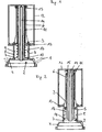
- a dispensing valve 2 has a closure element 4 which is adapted to the cross section of the opening of a container 1 and, after filling the container 1 with a flowable medium, for example a cleaning or disinfectant concentrate inserted into the container opening and permanently fixed, eg glued or welded, is.
- the closure element 4 is provided with a projecting into the interior of the container 1 pipe section 5, which merges via a converging guide member 3 in a pipe section 6, which has a smaller diameter than the pipe section 5.
- the tube section 5 has three outlet openings 7, 8, 9 arranged one above the other.
- a piston-like valve member 10 extends in the closed position Fig. 1 or 5 in an outermost position in which a flow connection between the interior of the container 1 through the outlet openings 7, 8, 9 is interrupted to the outside.
- a compression spring 16 is provided, which urges the valve member 10 in the closed position.
- the piston-like valve member 10 has an inwardly extending air inlet tube 11, which is guided centrally in the pipe section 6 at a distance therefrom.
- a pot-like cover 12 is placed on the inner end of the air inlet tube 11, which has a lower centering ring 13.
- an annular sealing edge 20 may be formed, such as Fig. 5 shows.
- the cover 12 includes a certain volume of air and prevents the flowable medium from entering the air inlet tube 11.
- holes 15 are provided in the upper end region.
- another tube 14 which protrudes slightly on the side of the valve member 10 from the inlet tube 11 and ends at a short distance to the cover 12:
- the further tube 14 causes a division of the incoming air to two Channels, so that even if flowable medium enters the air inlet tube 11, a ventilation can take place via the further tube 14.
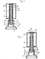
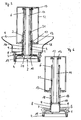
- FIG. 4 and 6 shows a third open position in which the valve member 10 is raised even higher, so that all top outlet openings 9 are exposed.
- the flowable medium can thus flow through all three openings 7, 8, 9 in a correspondingly large amount per unit time through the pipe section 5 downwards, wherein at the lower end of the pipe section 5 in the embodiment of FIGS. 5 and 6 an annular drip hood 19 is formed.
- the spring 16 receiving space 18 can, as FIGS. 5 and 6 show a vent 17 be assigned to allow the air to be displaced during the lifting of the valve member 10 to flow.
Landscapes
- Engineering & Computer Science (AREA)
- Mechanical Engineering (AREA)
- Closures For Containers (AREA)
Description
- Die Erfindung betrifft ein Ausgabeventil für die Abgabe eines fließfähigen Mediums aus einem kopfstehenden Behälter mit einem in die Behälteröffnung einsetzbaren hohlzylindrischen Verschlusselement, und mit einem in eine Offenstellung höhenverstellbaren Ventilteil, der im Verschlusselement kolbenartig dichtend geführt ist, und in Ruhestellung einen Auslass in einer Seitenwand des Verschlusselementes verschlossen hält, sowie einen mit einem derartigen Ausgabeventil versehenen Behälter.
- Derartige Ausgabeventile sind in einem Verschlusselement der Behälteröffnung angeordnet, in die sie im Allgemeinen nach der Füllung eingesetzt und fixiert werden. Um den Behälterinhalt insbesondere portionsweise entnehmen zu können, wird der Ventilteil in die Offenstellung bewegt, wofür verschiedene Möglichkeiten gegeben sind.
- Der Ventilteil kann verdreht werden. Beispiele für eine Dosiereinrichtung mit einem verdrehbaren Ventilteil zeigen die
WO 99/18026 US 5,715,877 US 1,428,744 undDE 478 432 . - Der Ventilteil kann axial verschoben werden. Ein Beispiel für eine Dosiereinrichtung mit einem axial verschiebbaren Ventilteil zeigt die
WO 93/13009 - Der Ventilteil kann verdreht und axial verschoben werden. Beispiele für eine Dosiereinrichtung mit einem derartigen Ventilteil zeigen die
WO 01/28914 WO 01/02283 US 6,045,119 . - Wenn das Ventil geöffnet ist, so fließt eine bestimmte Menge des Mediums aus, wobei die Menge vom Öffnungsquerschnitt und von der Öffnungszeit abhängt, beispielsweise von der Dauer der Betätigung einer entsprechenden Handhabe.
- Die Erfindung stellt nun ein Ausgabeventil zur Verfügung, mittels dem wahlweise zumindest zwei unterschiedliche Mengen pro Zeiteinheit aus dem Behälter entnommen werden können, indem zumindest zwei Offenstellungen mit unterschiedlichen Auslassquerschnitten durch diskrete Austrittsöffnungen bestimmt sind, die im Öffnungsweg des Ventitteils übereinander vorgesehen sind, wobei in der ersten Offenstellung eine erste Austrittsöffnung, und in der zweiten Offenstellung eine zweite Austrittsöffnung geöffnet ist.
- Dem Ausgabeventil ist bevorzugt pro Offenstellung eine Betätigungshandhabe zugeordnet, sodass durch Wahl der Handhabe der Ventilteil in die jeweilige Offenstellung überführt wird.
- Bei der Höhenverstellung des Ventilteiles werden somit nacheinander die einzelnen Offenstellungen erreicht.
- Dies bietet den Vorteil, dass die aus dem Behälter austretende Menge nicht von der präzisen Handhabung des Ventilteils abhängig ist, sodass Ungenauigkeiten aller Art, etwa bei der Herstellung des Ausgabeventils, bei der Herstellung des Behälters, in der Betätigungsmechanik der Dosiereinrichtung, usw. keine Auswirkungen auf die dosierte Menge aufweisen. Die jeweilige Weglänge bis zur Freigabe der entsprechenden Austrittsöffnung ist eher unkritisch.
- Bevorzugt kann dabei die erste Austrittsöffnung geöffnet bleiben, sodass der größere Auslassquerschnitt sich aus der Summe der beiden Austrittsöffnungen ergibt, wobei die zweite Austrittsöffnung kleiner, gleich oder größer sein kann, da sie in jedem Fall die erste Austrittsöffnung ergänzt
- Wenn der Behälter keine flexiblen, sondern im Wesentlichen steife Wandungen aufweist, so ist weiters vorgesehen, dass der Ventilteil einen axialen Lufteinlasskanal aufweist.
- Nachstehend werden zwei Ausführungsbeispiele der Erfindung an Hand der Figuren der beiliegenden Zeichnung näher beschrieben, ohne darauf beschränkt zu sein.
- Es zeigen:
DieFig. 1 bis 4 jeweils Axialschnitte durch ein in einen kopfstehenden Behälter eingesetztes Ausgabeventil, wobei ausFig. 1 die Schließ- oder Ruhestellung, ausFig. 2 eine erste Offenstellung, ausFig. 3 eine zweite Offenstellung und ausFig. 4 eine dritte Offenstellung ersichtlich ist, undFig. 5 und 6 Axialschnitte gemäßFig. 1 und4 durch ein zweites Ausführungsbeispiel. - Ein Ausgabeventil 2 weist ein an den Querschnitt der Öffnung eines Behälters 1 angepasstes Verschlusselement 4 auf, das nach der Befüllung des Behälters 1 mit einem fließfähigen Medium, beispielsweise einem Reinigungs- oder Desinfektionsmittelkonzentrat in die Behälteröffnung eingesetzt und dauerhaft fixiert, z.B. verklebt oder verschweißt, wird. Das Verschlusselement 4 ist mit einem in das Innere des Behälters 1 ragenden Rohrabschnitt 5 versehen, der über einen konvergierenden Führungsteil 3 in einen Rohrabschnitt 6 übergeht, der einen kleineren Durchmesser als der Rohrabschnitt 5 aufweist.
- Der Rohrabschnitt 5 weist im gezeigten Ausführungsbeispiel drei übereinander angeordnete Austrittsöffnungen 7, 8. 9 auf. Ein kolbenartiger Ventilteil 10 erstreckt sich in der Schließstellung nach
Fig. 1 oder5 in einer äußersten Position, in der eine Strömungsverbindung zwischen dem Inneren des Behälters 1 durch die Austrittsöffnungen 7, 8, 9 nach außen unterbrochen ist. Zwischen dem Ventilteil 10 und dem konvergierenden Führungsteil 3 ist eine Druckfeder 16 vorgesehen, die den Ventilteil 10 in die Schließstellung beaufschlagt. - Der kolbenartige Ventilteil 10 weist ein sich nach innen erstreckendes Lufteinlassrohr 11 auf, das mittig im Rohrabschnitt 6 mit Abstand dazu geführt ist. In der gezeigten Ausführung für kopfstehende Behälter ist auf das innere Ende des Lufteinlassrohres 11 eine topfartige Abdeckung 12 aufgesetzt, die einen unteren Zentrierring 13 aufweist. Am unteren Ende des Lufteinlassrohres 11 kann eine ringförmige Dichtkante 20 ausgebildet sein, wie
Fig. 5 zeigt. - Die Abdeckung 12 umfasst ein bestimmtes Luftvolumen und verhindert, dass das fließfähige Medium in das Lufteinlassrohr 11 eindringen kann. Für den Luftdurchtritt aus dem Einlassrohr 11 in die Abdeckung 12 sind im oberen Endbereich Löcher 15 vorgesehen. In der Ausführung nach
Fig. 1 bis 4 ist im Inneren des Einlassrohres 11 über nicht gezeigte Stege ein weiteres Rohr 14 gehalten, das an der Seite des Ventilteils 10 geringfügig aus dem Einlassrohr 11 vorsteht und mit geringem Abstand zur Abdeckung 12 endet: Das weitere Rohr 14 bewirkt eine Aufteilung der einströmenden Luft auf zwei Kanäle, sodass auch dann, wenn fließfähiges Medium in das Lufteinlassrohr 11 eindringt, eine Belüftung über das weitere Rohr 14 erfolgen kann. - In der Ausführung nach
Fig. 5 und 6 fehlt dieses weitere Rohr, da das Eindringen von fließfähigem Medium durch den Ringspalt zwischen dem Rohrabschnitt 6 des Verschlusselementes 4 und dem Lufteinlassrohr 11 durch einen etwa mittig angeordneten Dichtungsring 21 unterbunden wird. - In der Schließstellung nach
Fig. 1 oder5 sitzt die Abdeckung 12 dichtend auf dem Ende des Rohrabschnitts 6 und der Zentrierring 13 dichtend auf dem Führungsteil 3 auf. Um das Ventil zu öffnen und eine erste Menge des fließfähigen Mediums aus dem Behälter 1 nach unten ausströmen zu lassen, wird der Ventilteil 10 so weit angehoben, dass die unterste Austrittsöffnung 7 freigegeben wird. Mit dem Anheben des Ventilteils 10 hebt auch die Abdeckung 12 von ihren abgedichteten Sitzen am Ende des Rohrabschnitts 6 und dem Führungsteil 3 ab, sodass Luft durch die Löcher 15 in die Abdeckung 12 und durch deren unteren Zentrierring 13 in das Innere des Behälters 1 strömen kann. - Soll eine größere Menge des fließfähigen Mediums in der gleichen Zeiteinheit aus dem Behälter entnommen werden, so wird der Ventilteil 10 um eine größere Höhe angehoben (siehe
Fig. 3 ), sodass die nächsthöhere Austrittsöffnung 8 zusätzlich freigegeben wird. Der Gesamtaustrittsquerschnitt wird dadurch entsprechend größer.Fig. 4 und6 zeigt eine dritte Offenstellung, in der der Ventilteil 10 noch höher angehoben ist, sodass auch alle obersten Austrittsöffnungen 9 freiliegen. Das fließfähige Medium kann somit durch alle drei Öffnungen 7, 8, 9 in einer entsprechend großen Menge pro Zeiteinheit durch den Rohrabschnitt 5 nach unten ausfließen, wobei am unteren Ende des Rohrabschnitts 5 in der Ausführung nachFig. 5 und 6 eine ringförmige Abtropfhaube 19 ausgebildet ist. Dem die Feder 16 aufnehmenden Raum 18 kann, wieFig. 5 und 6 zeigen, eine Entlüftungsöffnung 17 zugeordnet sein, um die beim Anheben des Ventilteils 10 zu verdrängende Luft ausströmen zu lassen.
Claims (4)
- Ausgabeventil für die Abgabe eines fließfähigen Mediums aus einem kopfstehenden Behälter (1), mit einem in die Behälteröffnung einsetzbaren hohlzylindrischen Verschlusselement (4), und mit einem in eine Offenstellung höhenverstellbaren Ventilteil (10), der im Verschlusselement (4) kolbenartig dichtend geführt ist und in Ruhestellung einen Auslass in einer Seitenwand (5) des Verschlusselementes (4) verschlossen hält, dadurch gekennzeichnet, dass zumindest zwei Offenstellungen mit unterschiedlichen Auslassquerschnitten durch diskrete Austrittsöffnungen (7, 8) bestimmt sind, die im Öffnungsweg des Ventilteiles (10) übereinander vorgesehen sind, wobei in der ersten Offenstellung eine erste Austrittsöffnung (7), und in der zweiten Offenstellung eine zweite Austrittsöffnung (8) geöffnet ist.
- Ausgabeventil nach Anspruch 1, dadurch gekennzeichnet, dass in der zweiten Offenstellung beide Austrittsöffnungen (7, 8) geöffnet sind.
- Ausgabeventil nach Anspruch 1, dadurch gekennzeichnet, dass der Ventilteil (10) einen axialen Lufteinlasskanal (14) aufweist.
- Mit einem fließfähigen Medium gefüllter Behälter (1), der mit einem Ausgabeventil (2) nach einem der Ansprüche 1 bis 3 versehen ist, wobei das Ausgabeventil (2) eine Schließstellung, zumindest zwei übereinander angeordnete Offenstellungen und einen höhenverstellbaren Ventilteil (10) aufweist.
Priority Applications (2)
| Application Number | Priority Date | Filing Date | Title |
|---|---|---|---|
| PL05004649T PL1571122T3 (pl) | 2004-03-05 | 2005-03-03 | Zawór wylotowy |
| SI200531804T SI1571122T1 (sl) | 2004-03-05 | 2005-03-03 | Razdeljevalni ventil |
Applications Claiming Priority (2)
| Application Number | Priority Date | Filing Date | Title |
|---|---|---|---|
| AT0037904A AT500874B1 (de) | 2004-03-05 | 2004-03-05 | Ausgabeventil |
| AT3792004 | 2004-03-05 |
Publications (2)
| Publication Number | Publication Date |
|---|---|
| EP1571122A1 EP1571122A1 (de) | 2005-09-07 |
| EP1571122B1 true EP1571122B1 (de) | 2013-09-11 |
Family
ID=34744105
Family Applications (1)
| Application Number | Title | Priority Date | Filing Date |
|---|---|---|---|
| EP05004649.9A Expired - Lifetime EP1571122B1 (de) | 2004-03-05 | 2005-03-03 | Ausgabeventil |
Country Status (7)
| Country | Link |
|---|---|
| US (1) | US7441570B2 (de) |
| EP (1) | EP1571122B1 (de) |
| AT (1) | AT500874B1 (de) |
| ES (1) | ES2438530T3 (de) |
| PL (1) | PL1571122T3 (de) |
| PT (1) | PT1571122E (de) |
| SI (1) | SI1571122T1 (de) |
Families Citing this family (4)
| Publication number | Priority date | Publication date | Assignee | Title |
|---|---|---|---|---|
| US20090305379A1 (en) * | 2008-06-06 | 2009-12-10 | Johnson Matthew W | Digester system |
| GB2535982A (en) * | 2015-02-13 | 2016-09-07 | Nerudia Ltd | System and apparatus |
| AT519376B1 (de) | 2016-11-21 | 2018-08-15 | Georg Hagleitner Hans | In eine Behälteröffnung einsetzbares Verschlusselement |
| US11702255B2 (en) | 2021-04-20 | 2023-07-18 | Diversey, Inc. | Fluid container cap with dual-position restrictor |
Family Cites Families (18)
| Publication number | Priority date | Publication date | Assignee | Title |
|---|---|---|---|---|
| DE478432C (de) | 1929-06-25 | Franz Kubin | Zapfhahn mit Klappenventil | |
| DE51107C (de) * | H. C. WlLLMOTH in Kentish Town und G. GlLLET/ in London, Camden Road 314 | Mischhahn | ||
| US1428744A (en) | 1921-11-16 | 1922-09-12 | Bastian Blessing Co | Dispensing valve |
| US5249611A (en) * | 1987-03-16 | 1993-10-05 | Vemco, Inc. | Pour spout |
| US5211314A (en) | 1991-12-27 | 1993-05-18 | Ebtech, Inc. | Syrup dispenser and valve assembly |
| US5535794A (en) * | 1993-10-07 | 1996-07-16 | Posly; Louis M. | Water bottle closure |
| US5431205A (en) * | 1993-10-08 | 1995-07-11 | Gebhard; Albert W. | Dispensing system for bottled liquids |
| US5464127A (en) * | 1994-02-28 | 1995-11-07 | Ebtech, Inc. | Sealed actuator probe assembly for a bottled water station |
| FR2746890B1 (fr) | 1996-03-27 | 1998-09-11 | Flextainer | Robinet de distribution de liquides, en particulier de liquides alimentaires, a fermeture automatique muni d'un moyen de maintien en position d'ouverture du piston |
| US5715877A (en) | 1996-10-01 | 1998-02-10 | Champion Chemical Co. Of Calif., Inc. | Solution dilution assembly |
| ES2253602T3 (es) * | 1997-10-08 | 2006-06-01 | Minnesota Mining And Manufacturing Company | Capuchon protector de valvula dispensadora de fluido alimentado por gravedad. |
| US5944300A (en) * | 1998-06-05 | 1999-08-31 | Macmillan Bloedel Packaging | Bag and box valve system |
| AU5420400A (en) | 1999-07-06 | 2001-01-22 | Paul Roos | Taps for liquid flow control |
| US6223791B1 (en) | 1999-10-21 | 2001-05-01 | 3M Innovative Properties Company | Gravity feed fluid dispensing valve |
| CN1209278C (zh) * | 2000-12-18 | 2005-07-06 | 可得制品公司 | 配给阀门组件及其联接装置和关闭装置 |
| CA2351835A1 (en) * | 2001-06-28 | 2002-12-28 | Scepter Corporation | Spout with cut-away openings |
| US6968983B2 (en) * | 2002-02-12 | 2005-11-29 | Rodney Laible | Closed loop dispensing system |
| US6598630B1 (en) * | 2002-02-14 | 2003-07-29 | Midwest Can Company | Multi-flow pour spout |
-
2004
- 2004-03-05 AT AT0037904A patent/AT500874B1/de not_active IP Right Cessation
-
2005
- 2005-03-03 SI SI200531804T patent/SI1571122T1/sl unknown
- 2005-03-03 EP EP05004649.9A patent/EP1571122B1/de not_active Expired - Lifetime
- 2005-03-03 PT PT50046499T patent/PT1571122E/pt unknown
- 2005-03-03 PL PL05004649T patent/PL1571122T3/pl unknown
- 2005-03-03 ES ES05004649.9T patent/ES2438530T3/es not_active Expired - Lifetime
- 2005-03-07 US US11/073,904 patent/US7441570B2/en not_active Expired - Fee Related
Also Published As
| Publication number | Publication date |
|---|---|
| PL1571122T3 (pl) | 2014-02-28 |
| US7441570B2 (en) | 2008-10-28 |
| ES2438530T3 (es) | 2014-01-17 |
| EP1571122A1 (de) | 2005-09-07 |
| AT500874B1 (de) | 2006-11-15 |
| PT1571122E (pt) | 2013-12-10 |
| SI1571122T1 (sl) | 2014-02-28 |
| AT500874A1 (de) | 2006-04-15 |
| US20050194061A1 (en) | 2005-09-08 |
Similar Documents
| Publication | Publication Date | Title |
|---|---|---|
| DE69927786T2 (de) | Zapfhahn, umfassend einen Luftdurchlass | |
| DE19513931B4 (de) | Kappe für eine Kanne | |
| DE2208071C3 (de) | Vorrichtung für die Abgabe von wenigstens zwei getrennt in einer Aerosoldose befindlichen Produkten | |
| DE1817260A1 (de) | Mit einem Druck erzeugenden Treibmittel arbeitende Abgabevorrichtung | |
| EP3551808B1 (de) | Druckwasserventil | |
| DE69301974T2 (de) | Behälter zum spenden von flüssigkeiten | |
| DE112012002816T5 (de) | Tablettenausgabevorrichtung | |
| EP3013711A1 (de) | Spenderpatrone sowie spenderanordnung | |
| DE2052859A1 (de) | Aerosolventil | |
| DE1648150B2 (de) | Aerosolzumessventil | |
| EP3708512A1 (de) | Behälterverschluss und behälter | |
| DE1951696C3 (de) | Vorrichtung an Apparaten zur portionsweisen Entnahme flüssiger oder pastöser Erzeugnisse aus einem Behälter | |
| WO2012104351A1 (de) | Funktionskopf für einen duftstoffbehälter | |
| EP1571122B1 (de) | Ausgabeventil | |
| DE102009044280A1 (de) | Produktspender | |
| DE8715785U1 (de) | Ventil | |
| DE4140524C2 (de) | Füllorgan für Getränkefüller mit eine Gassperre aufweisendem Flüssigkeitsventil | |
| DE4140525C1 (de) | ||
| WO2018090068A1 (de) | In eine behälteröffnung einsetzbares verschlusselement, und behälter | |
| EP1196248A1 (de) | Umschaltdüsenkopf für ein hochdruckreinigungsgerät | |
| DE2528006B2 (de) | Dosierverschluß für Streugutspender | |
| DE602005005214T2 (de) | Ventile für trinkbecher | |
| AT500506B1 (de) | Vorrichtung zur abgabe eines fliessfähigen mediums | |
| DE2715898A1 (de) | Ventil, insbesondere elektromagnetisch betaetigbares ventil | |
| DE20021821U1 (de) | Dosierspender |
Legal Events
| Date | Code | Title | Description |
|---|---|---|---|
| PUAI | Public reference made under article 153(3) epc to a published international application that has entered the european phase |
Free format text: ORIGINAL CODE: 0009012 |
|
| AK | Designated contracting states |
Kind code of ref document: A1 Designated state(s): AT BE BG CH CY CZ DE DK EE ES FI FR GB GR HU IE IS IT LI LT LU MC NL PL PT RO SE SI SK TR |
|
| AX | Request for extension of the european patent |
Extension state: AL BA HR LV MK YU |
|
| 17P | Request for examination filed |
Effective date: 20060301 |
|
| AKX | Designation fees paid |
Designated state(s): AT BE BG CH CY CZ DE DK EE ES FI FR GB GR HU IE IS IT LI LT LU MC NL PL PT RO SE SI SK TR |
|
| 17Q | First examination report despatched |
Effective date: 20120626 |
|
| GRAP | Despatch of communication of intention to grant a patent |
Free format text: ORIGINAL CODE: EPIDOSNIGR1 |
|
| INTG | Intention to grant announced |
Effective date: 20130417 |
|
| GRAS | Grant fee paid |
Free format text: ORIGINAL CODE: EPIDOSNIGR3 |
|
| GRAA | (expected) grant |
Free format text: ORIGINAL CODE: 0009210 |
|
| AK | Designated contracting states |
Kind code of ref document: B1 Designated state(s): AT BE BG CH CY CZ DE DK EE ES FI FR GB GR HU IE IS IT LI LT LU MC NL PL PT RO SE SI SK TR |
|
| REG | Reference to a national code |
Ref country code: GB Ref legal event code: FG4D Free format text: NOT ENGLISH |
|
| REG | Reference to a national code |
Ref country code: CH Ref legal event code: EP |
|
| REG | Reference to a national code |
Ref country code: AT Ref legal event code: REF Ref document number: 631507 Country of ref document: AT Kind code of ref document: T Effective date: 20130915 |
|
| REG | Reference to a national code |
Ref country code: IE Ref legal event code: FG4D Free format text: LANGUAGE OF EP DOCUMENT: GERMAN |
|
| REG | Reference to a national code |
Ref country code: DE Ref legal event code: R096 Ref document number: 502005013958 Country of ref document: DE Effective date: 20131107 |
|
| REG | Reference to a national code |
Ref country code: RO Ref legal event code: EPE |
|
| REG | Reference to a national code |
Ref country code: PT Ref legal event code: SC4A Free format text: AVAILABILITY OF NATIONAL TRANSLATION Effective date: 20131203 |
|
| REG | Reference to a national code |
Ref country code: NL Ref legal event code: T3 |
|
| REG | Reference to a national code |
Ref country code: SE Ref legal event code: TRGR |
|
| REG | Reference to a national code |
Ref country code: ES Ref legal event code: FG2A Ref document number: 2438530 Country of ref document: ES Kind code of ref document: T3 Effective date: 20140117 |
|
| PG25 | Lapsed in a contracting state [announced via postgrant information from national office to epo] |
Ref country code: CY Free format text: LAPSE BECAUSE OF FAILURE TO SUBMIT A TRANSLATION OF THE DESCRIPTION OR TO PAY THE FEE WITHIN THE PRESCRIBED TIME-LIMIT Effective date: 20130619 Ref country code: LT Free format text: LAPSE BECAUSE OF FAILURE TO SUBMIT A TRANSLATION OF THE DESCRIPTION OR TO PAY THE FEE WITHIN THE PRESCRIBED TIME-LIMIT Effective date: 20130911 |
|
| REG | Reference to a national code |
Ref country code: LT Ref legal event code: MG4D |
|
| PG25 | Lapsed in a contracting state [announced via postgrant information from national office to epo] |
Ref country code: FI Free format text: LAPSE BECAUSE OF FAILURE TO SUBMIT A TRANSLATION OF THE DESCRIPTION OR TO PAY THE FEE WITHIN THE PRESCRIBED TIME-LIMIT Effective date: 20130911 Ref country code: GR Free format text: LAPSE BECAUSE OF FAILURE TO SUBMIT A TRANSLATION OF THE DESCRIPTION OR TO PAY THE FEE WITHIN THE PRESCRIBED TIME-LIMIT Effective date: 20131212 |
|
| REG | Reference to a national code |
Ref country code: PL Ref legal event code: T3 Ref country code: CH Ref legal event code: NV Representative=s name: ISLER AND PEDRAZZINI AG, CH |
|
| PG25 | Lapsed in a contracting state [announced via postgrant information from national office to epo] |
Ref country code: CY Free format text: LAPSE BECAUSE OF FAILURE TO SUBMIT A TRANSLATION OF THE DESCRIPTION OR TO PAY THE FEE WITHIN THE PRESCRIBED TIME-LIMIT Effective date: 20130911 |
|
| REG | Reference to a national code |
Ref country code: SK Ref legal event code: T3 Ref document number: E 15424 Country of ref document: SK |
|
| PG25 | Lapsed in a contracting state [announced via postgrant information from national office to epo] |
Ref country code: IS Free format text: LAPSE BECAUSE OF FAILURE TO SUBMIT A TRANSLATION OF THE DESCRIPTION OR TO PAY THE FEE WITHIN THE PRESCRIBED TIME-LIMIT Effective date: 20140111 Ref country code: EE Free format text: LAPSE BECAUSE OF FAILURE TO SUBMIT A TRANSLATION OF THE DESCRIPTION OR TO PAY THE FEE WITHIN THE PRESCRIBED TIME-LIMIT Effective date: 20130911 |
|
| REG | Reference to a national code |
Ref country code: DE Ref legal event code: R097 Ref document number: 502005013958 Country of ref document: DE |
|
| PLBE | No opposition filed within time limit |
Free format text: ORIGINAL CODE: 0009261 |
|
| STAA | Information on the status of an ep patent application or granted ep patent |
Free format text: STATUS: NO OPPOSITION FILED WITHIN TIME LIMIT |
|
| 26N | No opposition filed |
Effective date: 20140612 |
|
| REG | Reference to a national code |
Ref country code: DE Ref legal event code: R097 Ref document number: 502005013958 Country of ref document: DE Effective date: 20140612 |
|
| REG | Reference to a national code |
Ref country code: HU Ref legal event code: AG4A Ref document number: E020395 Country of ref document: HU |
|
| PG25 | Lapsed in a contracting state [announced via postgrant information from national office to epo] |
Ref country code: DK Free format text: LAPSE BECAUSE OF FAILURE TO SUBMIT A TRANSLATION OF THE DESCRIPTION OR TO PAY THE FEE WITHIN THE PRESCRIBED TIME-LIMIT Effective date: 20130911 |
|
| PG25 | Lapsed in a contracting state [announced via postgrant information from national office to epo] |
Ref country code: LU Free format text: LAPSE BECAUSE OF FAILURE TO SUBMIT A TRANSLATION OF THE DESCRIPTION OR TO PAY THE FEE WITHIN THE PRESCRIBED TIME-LIMIT Effective date: 20140303 |
|
| REG | Reference to a national code |
Ref country code: IE Ref legal event code: MM4A |
|
| PG25 | Lapsed in a contracting state [announced via postgrant information from national office to epo] |
Ref country code: IE Free format text: LAPSE BECAUSE OF NON-PAYMENT OF DUE FEES Effective date: 20140303 |
|
| REG | Reference to a national code |
Ref country code: FR Ref legal event code: PLFP Year of fee payment: 12 |
|
| PG25 | Lapsed in a contracting state [announced via postgrant information from national office to epo] |
Ref country code: MC Free format text: LAPSE BECAUSE OF FAILURE TO SUBMIT A TRANSLATION OF THE DESCRIPTION OR TO PAY THE FEE WITHIN THE PRESCRIBED TIME-LIMIT Effective date: 20130911 |
|
| PG25 | Lapsed in a contracting state [announced via postgrant information from national office to epo] |
Ref country code: BE Free format text: LAPSE BECAUSE OF FAILURE TO SUBMIT A TRANSLATION OF THE DESCRIPTION OR TO PAY THE FEE WITHIN THE PRESCRIBED TIME-LIMIT Effective date: 20140331 |
|
| REG | Reference to a national code |
Ref country code: FR Ref legal event code: PLFP Year of fee payment: 13 |
|
| REG | Reference to a national code |
Ref country code: FR Ref legal event code: PLFP Year of fee payment: 14 |
|
| PGFP | Annual fee paid to national office [announced via postgrant information from national office to epo] |
Ref country code: RO Payment date: 20180221 Year of fee payment: 14 Ref country code: GB Payment date: 20180329 Year of fee payment: 14 Ref country code: CH Payment date: 20180323 Year of fee payment: 14 Ref country code: CZ Payment date: 20180219 Year of fee payment: 14 Ref country code: NL Payment date: 20180323 Year of fee payment: 14 |
|
| PGFP | Annual fee paid to national office [announced via postgrant information from national office to epo] |
Ref country code: SK Payment date: 20180220 Year of fee payment: 14 Ref country code: PL Payment date: 20180216 Year of fee payment: 14 Ref country code: SI Payment date: 20180219 Year of fee payment: 14 Ref country code: TR Payment date: 20180219 Year of fee payment: 14 Ref country code: HU Payment date: 20180214 Year of fee payment: 14 Ref country code: FR Payment date: 20180329 Year of fee payment: 14 Ref country code: AT Payment date: 20180327 Year of fee payment: 14 Ref country code: PT Payment date: 20180219 Year of fee payment: 14 Ref country code: SE Payment date: 20180319 Year of fee payment: 14 Ref country code: BG Payment date: 20180327 Year of fee payment: 14 Ref country code: IT Payment date: 20180320 Year of fee payment: 14 |
|
| PGFP | Annual fee paid to national office [announced via postgrant information from national office to epo] |
Ref country code: ES Payment date: 20180423 Year of fee payment: 14 Ref country code: DE Payment date: 20180530 Year of fee payment: 14 |
|
| REG | Reference to a national code |
Ref country code: DE Ref legal event code: R119 Ref document number: 502005013958 Country of ref document: DE |
|
| REG | Reference to a national code |
Ref country code: SE Ref legal event code: EUG |
|
| PG25 | Lapsed in a contracting state [announced via postgrant information from national office to epo] |
Ref country code: CZ Free format text: LAPSE BECAUSE OF NON-PAYMENT OF DUE FEES Effective date: 20190303 Ref country code: SI Free format text: LAPSE BECAUSE OF NON-PAYMENT OF DUE FEES Effective date: 20190304 Ref country code: RO Free format text: LAPSE BECAUSE OF NON-PAYMENT OF DUE FEES Effective date: 20190303 Ref country code: SE Free format text: LAPSE BECAUSE OF NON-PAYMENT OF DUE FEES Effective date: 20190304 Ref country code: PT Free format text: LAPSE BECAUSE OF NON-PAYMENT OF DUE FEES Effective date: 20190903 |
|
| REG | Reference to a national code |
Ref country code: CH Ref legal event code: PL |
|
| REG | Reference to a national code |
Ref country code: NL Ref legal event code: MM Effective date: 20190401 |
|
| REG | Reference to a national code |
Ref country code: AT Ref legal event code: MM01 Ref document number: 631507 Country of ref document: AT Kind code of ref document: T Effective date: 20190303 |
|
| GBPC | Gb: european patent ceased through non-payment of renewal fee |
Effective date: 20190303 |
|
| REG | Reference to a national code |
Ref country code: SI Ref legal event code: KO00 Effective date: 20191007 |
|
| REG | Reference to a national code |
Ref country code: SK Ref legal event code: MM4A Ref document number: E 15424 Country of ref document: SK Effective date: 20190303 |
|
| PG25 | Lapsed in a contracting state [announced via postgrant information from national office to epo] |
Ref country code: NL Free format text: LAPSE BECAUSE OF NON-PAYMENT OF DUE FEES Effective date: 20190401 Ref country code: DE Free format text: LAPSE BECAUSE OF NON-PAYMENT OF DUE FEES Effective date: 20191001 Ref country code: LI Free format text: LAPSE BECAUSE OF NON-PAYMENT OF DUE FEES Effective date: 20190331 Ref country code: AT Free format text: LAPSE BECAUSE OF NON-PAYMENT OF DUE FEES Effective date: 20190303 Ref country code: GB Free format text: LAPSE BECAUSE OF NON-PAYMENT OF DUE FEES Effective date: 20190303 Ref country code: CH Free format text: LAPSE BECAUSE OF NON-PAYMENT OF DUE FEES Effective date: 20190331 Ref country code: BG Free format text: LAPSE BECAUSE OF NON-PAYMENT OF DUE FEES Effective date: 20190930 Ref country code: HU Free format text: LAPSE BECAUSE OF NON-PAYMENT OF DUE FEES Effective date: 20190304 Ref country code: SK Free format text: LAPSE BECAUSE OF NON-PAYMENT OF DUE FEES Effective date: 20190303 |
|
| PG25 | Lapsed in a contracting state [announced via postgrant information from national office to epo] |
Ref country code: IT Free format text: LAPSE BECAUSE OF NON-PAYMENT OF DUE FEES Effective date: 20190303 Ref country code: FR Free format text: LAPSE BECAUSE OF NON-PAYMENT OF DUE FEES Effective date: 20190331 |
|
| REG | Reference to a national code |
Ref country code: ES Ref legal event code: FD2A Effective date: 20200724 |
|
| PG25 | Lapsed in a contracting state [announced via postgrant information from national office to epo] |
Ref country code: ES Free format text: LAPSE BECAUSE OF NON-PAYMENT OF DUE FEES Effective date: 20190304 |
|
| PG25 | Lapsed in a contracting state [announced via postgrant information from national office to epo] |
Ref country code: PL Free format text: LAPSE BECAUSE OF NON-PAYMENT OF DUE FEES Effective date: 20190303 |
|
| PG25 | Lapsed in a contracting state [announced via postgrant information from national office to epo] |
Ref country code: TR Free format text: LAPSE BECAUSE OF NON-PAYMENT OF DUE FEES Effective date: 20190303 |