EP1571060A1 - Fahrzeug mit einer pneumatischen Steuerleitung für Anhängerbremsen - Google Patents
Fahrzeug mit einer pneumatischen Steuerleitung für Anhängerbremsen Download PDFInfo
- Publication number
- EP1571060A1 EP1571060A1 EP05101748A EP05101748A EP1571060A1 EP 1571060 A1 EP1571060 A1 EP 1571060A1 EP 05101748 A EP05101748 A EP 05101748A EP 05101748 A EP05101748 A EP 05101748A EP 1571060 A1 EP1571060 A1 EP 1571060A1
- Authority
- EP
- European Patent Office
- Prior art keywords
- vehicle
- valve
- trailer
- pressure
- control line
- Prior art date
- Legal status (The legal status is an assumption and is not a legal conclusion. Google has not performed a legal analysis and makes no representation as to the accuracy of the status listed.)
- Granted
Links
- 230000001105 regulatory effect Effects 0.000 claims abstract description 5
- 230000009977 dual effect Effects 0.000 claims description 11
- 239000003570 air Substances 0.000 description 9
- 230000005540 biological transmission Effects 0.000 description 7
- 230000000694 effects Effects 0.000 description 2
- 238000012423 maintenance Methods 0.000 description 2
- 241001481828 Glyptocephalus cynoglossus Species 0.000 description 1
- 239000012080 ambient air Substances 0.000 description 1
- 238000010586 diagram Methods 0.000 description 1
- 230000000116 mitigating effect Effects 0.000 description 1
Images
Classifications
-
- B—PERFORMING OPERATIONS; TRANSPORTING
- B60—VEHICLES IN GENERAL
- B60T—VEHICLE BRAKE CONTROL SYSTEMS OR PARTS THEREOF; BRAKE CONTROL SYSTEMS OR PARTS THEREOF, IN GENERAL; ARRANGEMENT OF BRAKING ELEMENTS ON VEHICLES IN GENERAL; PORTABLE DEVICES FOR PREVENTING UNWANTED MOVEMENT OF VEHICLES; VEHICLE MODIFICATIONS TO FACILITATE COOLING OF BRAKES
- B60T13/00—Transmitting braking action from initiating means to ultimate brake actuator with power assistance or drive; Brake systems incorporating such transmitting means, e.g. air-pressure brake systems
- B60T13/10—Transmitting braking action from initiating means to ultimate brake actuator with power assistance or drive; Brake systems incorporating such transmitting means, e.g. air-pressure brake systems with fluid assistance, drive, or release
- B60T13/24—Transmitting braking action from initiating means to ultimate brake actuator with power assistance or drive; Brake systems incorporating such transmitting means, e.g. air-pressure brake systems with fluid assistance, drive, or release the fluid being gaseous
- B60T13/26—Compressed-air systems
- B60T13/261—Compressed-air systems systems with both indirect application and application by springs or weights and released by compressed air
- B60T13/263—Compressed-air systems systems with both indirect application and application by springs or weights and released by compressed air specially adapted for coupling with dependent systems, e.g. tractor-trailer systems
-
- B—PERFORMING OPERATIONS; TRANSPORTING
- B60—VEHICLES IN GENERAL
- B60T—VEHICLE BRAKE CONTROL SYSTEMS OR PARTS THEREOF; BRAKE CONTROL SYSTEMS OR PARTS THEREOF, IN GENERAL; ARRANGEMENT OF BRAKING ELEMENTS ON VEHICLES IN GENERAL; PORTABLE DEVICES FOR PREVENTING UNWANTED MOVEMENT OF VEHICLES; VEHICLE MODIFICATIONS TO FACILITATE COOLING OF BRAKES
- B60T13/00—Transmitting braking action from initiating means to ultimate brake actuator with power assistance or drive; Brake systems incorporating such transmitting means, e.g. air-pressure brake systems
- B60T13/10—Transmitting braking action from initiating means to ultimate brake actuator with power assistance or drive; Brake systems incorporating such transmitting means, e.g. air-pressure brake systems with fluid assistance, drive, or release
- B60T13/66—Electrical control in fluid-pressure brake systems
- B60T13/68—Electrical control in fluid-pressure brake systems by electrically-controlled valves
- B60T13/683—Electrical control in fluid-pressure brake systems by electrically-controlled valves in pneumatic systems or parts thereof
Definitions
- the present invention relates to a vehicle having a braking circuit operated by at least one brake pedal, a parking brake and a pneumatic control line for connection to a trailer to operate the brakes of the trailer when the vehicle is braked.
- a dual line control valve has been used to regulate the pneumatic pressure in the trailer brake control line.
- Such a valve receives, as a first input, a pneumatic pressure that is generated only when both brake pedals are initially applied, thereby opening a (normally closed) brake switch (having dual normally open and normally closed contacts) provided on each brake pedal.
- the switches which also serve as brake light operating switches (using the normally open contacts), are positioned to be closed before the vehicle brakes are applied in the electrical circuits that operate the "advance" trailer braking solenoid valve and the automatic four wheel drive engagement on the vehicle. This mode of application ensures failsafe operation of both systems.
- the "advance" trailer braking solenoid valve applies air tank pressure to the air operation spool of the dual line control valve.
- the valve then supplies about 1 to 2 Bar “advance” control pressure to the trailer to allow the trailer to be braked before the brakes of the vehicle take effect, to allow smooth and safe braking.
- a further regulating valve may be provided to allow the driver to manually adjust the "advance” or delay between the braking of the trailer and the towing vehicle depending on the prevailing operating conditions of the type of trailer hauled.
- the dual line control valve receives, as a second input, the hydraulic pressure applied to the wheels on both sides of the vehicle under increased braking. This pressure operates the hydraulic spool of the control valve and allows uniform increase of the trailer brake air control pressure towards maximum as the towing vehicle is being braked.
- a mechanical connection such as a Bowden cable or rod linkage
- the vehicle parking brake operating arm (provided on the vehicle transmission) and the dual line control valve, which sets the pressure in the pneumatic trailer brake control line.
- the operation at the dual line control valve is achieved by the cable/rod rotating an integral end cap which moves out over a ball/ramp device, manually moving the valve spool out and setting the pressure in the pneumatic trailer brake control line.
- the valve spool moves out only a very small amount, hence the ball/ramp only operates over a very minute angle of the total rotation available. Since operating on a ball/ramp device, the operating cable/linkage needs to be rigid.
- control valve cable/rod may travel too far and because of the small operation angle of the ball/ramp, as discussed previously, the end cap on the control valve may move too far over the ball/ramp, and the trailer brakes will release with full operation of the vehicle handbrake control.
- This failure mode could also happen if the vehicle transmission brake wears significantly, resulting in excessive handbrake operating lever travel, and lack of maintenance in not readjusting the control valve cable/rod. It will be appreciated that the above adjustments must be carried out accurately by trained personnel, adding to the overall costs of maintenance.
- another fundamental shortcoming of the currently known systems include a lack of trailer brake operation upon failure of the cable or rod or any other links to the control valve.
- the present invention provides a vehicle having a braking circuit operated by at least one brake pedal, a parking brake and a pneumatic control line for connection to a trailer to operate the brakes of the trailer when the vehicle is braked, the vehicle comprising a first, pressure operated, valve for regulating the pressure in the pneumatic control line upon application of the vehicle brake pedal and a second, electrically operated, valve acting in parallel with the first valve to apply a pneumatic pressure to the control line in response to operation of the vehicle parking brake.
- the first and second valves are connected to the pneumatic control line my means of a priority valve that automatically establishes a connection between the control line and whichever of the first and second valves has the higher output pressure.
- the first valve is a dual line control valve, this too is not fundamental to the invention, the aim of which is to brake the trailer, with the most failsafe operation possible, when the parking brake of the vehicle is applied without there being a mechanical connection to the parking brake.
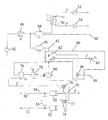
- the vehicle has left and right brake pedals 16 and 18 connected to left and right master cylinders 20 and 22 connected, respectively, to the lines 10 and 12 which lead to the slave cylinders operating the left and right brakes of the vehicle.
- the provision of separate brake pedals for the left and right side of the vehicle is to allow the vehicle to be steered by its brakes in off-road conditions.
- the pedals 16 and 18 are ganged together as represented by the dotted line linking them.
- a logic valve 24 connected to the lines 10 and 12 is closed when the brakes on the opposite sides of the vehicle are not applied equally.
- both brakes are applied at the same time, however, signifying that the vehicle is being braked rather than steered, the valve 24 opens and applies the hydraulic pressure in the lines 10 and 12 to the line 14, which controls the braking of the trailer.
- the brakes of the trailer operate pneumatically and are connected to two output lines 40 and 50 of the vehicle, termed the red supply line and the yellow control line, respectively.
- the red line 40 is under a constant high pressure and provides stored pressure towards the trailer which is the power for operating the air brake actuators of the trailer.
- the yellow line 50 is a control line which regulates the braking force via a relay emergency valve (not shown) on the trailer.
- Ambient air pressurised by a compressor 42 is supplied to two linked accumulators 44 and 46 by way of a pressure regulator 48.
- the accumulators 44 & 46 provide compressed air to the red line 40.
- a meter 52 indicates the available braking pressure and a warning light 54, operated by a pressure switch 56, alerts the driver when the available braking pressure drops below a safe limit.
- the accumulators also provide the compressed air for the yellow control line 50.
- the brake pedals 16 and 18 are associated with electrical switches 70 and 72 which may also serve as brake light switches. The travel of the brake pedals required to operate these switches is less than that required to operate the brakes of the vehicle.
- the switches 70 and 72 interrupt an electrical signal on a line towards a solenoid valve 76 before the vehicle brakes begin to take effect.
- This zero volt signal on said line allows the normally open solenoid valve 76 to supply compressed air through a valve 78 to a first control input of a dual line control valve (DLCV) 60.
- DLCV 60 increases the pressure in the yellow control line 50 to approximately 1 to 2 bar before the vehicle brakes are applied so that the trailer is braked before the vehicle.
- the regulator valve 78 allows the driver to set manually the delay between the application of the trailer brakes and the application of the vehicle brakes.
- the braking system as so far described is conventional and it is not therefore believed necessary for it to be described in further detail. To understand the invention, it suffices to appreciate that the DLCV 60 acts to operate the trailer brakes when the vehicle is being braked.
- the vehicle also has a hand brake (not shown) which can be used as a parking brake or as an emergency brake.
- the parking brake would be mechanically connected to the DLCV 60, for example by means of a Bowden cable or rod linkage, to act directly on the valve spool of the DLCV 60 and thereby operate the trailer brakes when the parking brake is applied.
- the requirement for a mechanical connection to the DLCV 60 places limitations on where it can be positioned and results in other disadvantages as discussed above.
- the handbrake operates on brake plates, usually in the transmission, which are prone to wear, especially when the vehicle is still relatively new.
- the movement required of the handbrake for it to apply the brakes effectively increases.
- the mechanical linkage is in constant need of re-adjustment otherwise the ball/ramp device inside the DLCV 60 would be pushed too far, resulting in the DLCV 60 to be turned off again. All this would result in the vehicle to be braked, but not the trailer.
- the invention provides the elements shown within the box 80 drawn in dotted lines. These elements obviate the need for a Bowden cable/rod connection or other mechanical connection between the handbrake and the DLCV 60.
- a (normally open) solenoid operated air valve 82 connected to the accumulators 44 and 46 is operated by a switch 84 which is open when the parking brake is applied.
- the output of the solenoid valve 82 (maximum tank and operating pressure) is applied to the yellow control line 50 by way of a priority valve 86 which acts to supply to the yellow line 50 the higher of the output pressures of the DLCV 60 and the solenoid valve 82, while maintaining the two output lines isolated from one another.
- the priority valve may for example comprise a ball movable in a housing having valve seats at each end and an output connection to the yellow line 50 at its centre.
- the opening of the switch 84 will provide zero volts to the normally open solenoid valve 82 and will apply maximum pressure to the yellow line 50 to fully apply the brakes on the trailer.
- the solenoid valve 82 can be housed in the same housing as the DLCV (60) or it may be mounted separately. As the valve only requires an electrical connection to the parking brake, it may be positioned at will on the vehicle.
- the system according to the invention has many commercially viable and more importantly, operational safety aspects. No mechanical operation linkage from the vehicle transmission brake lever to the control valve is required, making assembly far easier and resulting in an overall cost saving. No accurate initial adjustment is required, and no re-adjustment is required at service intervals. Even if the vehicle handbrake cable would fail, trailer brakes will still apply from the vehicle handbrake lever, through operation of the electrical switch 84. A reduction in additional undue wear to the control valve operating spool will be apparent, as the handbrake no longer has a connection to a manually operated part of the DLCV 60. As such, the manually operated part of the DLCV 60 can be deleted, resulting in a cheaper valve and hence a cost saving.
- Solenoid valve 82 operating the control line, is, as already mentioned, normally open under spring action. This means that, if the system loses 12 volt supply, e.g. as a result of relay or fuse failure, or wiring disconnection, it is fail safe and the trailer brakes will apply fully.
- the vehicle handbrake system switch 84 is also a normally open witch, i.e. when the handbrake is applied, the switch is open. Hence, if the switch comes adrift or the wiring disconnects (even if the handbrake is not applied), again the system will be failsafe and the trailer brakes will apply.
- the switch 84 operates as soon as the vehicle handbrake lever is applied and the trailer brakes are guaranteed to apply prior to the tractor brakes (to prevent jackknife-action during an emergency braking situation). If the operator leaves the vehicle cab and does not apply the handbrake, when the engine is off, no 12 volts are supplied to the solenoid 82, meaning that the trailer brakes are automatically applied.
- the system can easily be electrically linked into a transmission park lever switch or a seat proximity switch and the vehicle speed sensor to offer even further failsafe protection.
Landscapes
- Engineering & Computer Science (AREA)
- Transportation (AREA)
- Mechanical Engineering (AREA)
- Regulating Braking Force (AREA)
- Braking Systems And Boosters (AREA)
- Valves And Accessory Devices For Braking Systems (AREA)
- Hydraulic Control Valves For Brake Systems (AREA)
Applications Claiming Priority (2)
| Application Number | Priority Date | Filing Date | Title |
|---|---|---|---|
| GB0405087 | 2004-03-06 | ||
| GB0405087A GB2411705A (en) | 2004-03-06 | 2004-03-06 | Vehicle with a pneumatic control line for operating the brakes of a trailer |
Publications (2)
| Publication Number | Publication Date |
|---|---|
| EP1571060A1 true EP1571060A1 (de) | 2005-09-07 |
| EP1571060B1 EP1571060B1 (de) | 2006-10-04 |
Family
ID=32088844
Family Applications (1)
| Application Number | Title | Priority Date | Filing Date |
|---|---|---|---|
| EP05101748A Active EP1571060B1 (de) | 2004-03-06 | 2005-03-07 | Fahrzeug mit einer pneumatischen Steuerleitung für Anhängerbremsen |
Country Status (4)
| Country | Link |
|---|---|
| EP (1) | EP1571060B1 (de) |
| AT (1) | ATE341470T1 (de) |
| DE (1) | DE602005000153T2 (de) |
| GB (1) | GB2411705A (de) |
Cited By (6)
| Publication number | Priority date | Publication date | Assignee | Title |
|---|---|---|---|---|
| EP2163447A1 (de) * | 2007-03-23 | 2010-03-17 | KNORR-BREMSE Systeme für Nutzfahrzeuge GmbH | Druckmittelbetätigte Bremsanlage eines Fahrzeugs mit gegeläufige Drücke für Anhängerbremsen erzeugender Feststellbremseinrichtung |
| EP2165901A1 (de) * | 2008-09-20 | 2010-03-24 | Haldex Brake Products GmbH | Bremseinrichtung für ein hydraulisch gebremstes Zugfahrzeug mit pneumatisch gebremstem Anhänger |
| US8840197B2 (en) | 2011-06-10 | 2014-09-23 | Bendix Commercial Vehicle Systems, Llc | Hand control brake valve |
| WO2016105311A1 (en) * | 2014-12-26 | 2016-06-30 | Turk Traktor Ve Ziraat Makinalari Anonim | Parking brake mechanism integrated with pneumatic trailer brake |
| CN108556830A (zh) * | 2018-05-24 | 2018-09-21 | 湖南汽车工程职业学院 | 一种电控气压汽车制动系统及其控制方法 |
| CN110065483A (zh) * | 2019-04-10 | 2019-07-30 | 徐工集团工程机械股份有限公司科技分公司 | 一种常闭式湿式制动系统 |
Families Citing this family (3)
| Publication number | Priority date | Publication date | Assignee | Title |
|---|---|---|---|---|
| DE102009029898A1 (de) | 2009-06-23 | 2010-12-30 | Wabco Gmbh | Druckluftversorgungssystem für einen Druckluftverbraucherkreis, insbesondere für ein Luftfederungssystem |
| DE102009045191C5 (de) † | 2009-09-30 | 2020-08-13 | Haldex Brake Products Aktiebolag | Verfahren zum Betrieb einer Bremseinrichtung für ein hydraulisch gebremstes Zugfahrzeug |
| CN102343902B (zh) * | 2010-07-27 | 2014-08-13 | 徐州重型机械有限公司 | 气压制动单元及采用该制动单元的多轴汽车底盘 |
Citations (4)
| Publication number | Priority date | Publication date | Assignee | Title |
|---|---|---|---|---|
| DE679682C (de) * | 1928-11-11 | 1939-08-11 | Bosch Gmbh Robert | Bremseinrichtung fuer Wagenzuege |
| DE3431674A1 (de) * | 1984-08-29 | 1986-03-13 | Robert Bosch Gmbh, 7000 Stuttgart | Anhaengersteuerventil |
| US4616881A (en) * | 1982-05-21 | 1986-10-14 | Robert Bosch Gmbh | Tractor-trailer brake system including a trailer brake control valve |
| US4671578A (en) * | 1985-04-25 | 1987-06-09 | Wabco Westinghouse Fahrzeugbremsen Gmbh | Fluid pressure responsive brake for the trailer of a vehicle |
Family Cites Families (2)
| Publication number | Priority date | Publication date | Assignee | Title |
|---|---|---|---|---|
| DE3310768A1 (de) * | 1983-03-24 | 1984-09-27 | Xaver Fendt & Co, 8952 Marktoberdorf | Bremseinrichtung fuer anhaenger von zugmaschinen |
| DE3410270C2 (de) * | 1984-03-21 | 1996-01-25 | Rolf Teibtner | Bremseinrichtung für Anhänger von Zugfahrzeugen |
-
2004
- 2004-03-06 GB GB0405087A patent/GB2411705A/en not_active Withdrawn
-
2005
- 2005-03-07 DE DE602005000153T patent/DE602005000153T2/de active Active
- 2005-03-07 AT AT05101748T patent/ATE341470T1/de not_active IP Right Cessation
- 2005-03-07 EP EP05101748A patent/EP1571060B1/de active Active
Patent Citations (4)
| Publication number | Priority date | Publication date | Assignee | Title |
|---|---|---|---|---|
| DE679682C (de) * | 1928-11-11 | 1939-08-11 | Bosch Gmbh Robert | Bremseinrichtung fuer Wagenzuege |
| US4616881A (en) * | 1982-05-21 | 1986-10-14 | Robert Bosch Gmbh | Tractor-trailer brake system including a trailer brake control valve |
| DE3431674A1 (de) * | 1984-08-29 | 1986-03-13 | Robert Bosch Gmbh, 7000 Stuttgart | Anhaengersteuerventil |
| US4671578A (en) * | 1985-04-25 | 1987-06-09 | Wabco Westinghouse Fahrzeugbremsen Gmbh | Fluid pressure responsive brake for the trailer of a vehicle |
Cited By (8)
| Publication number | Priority date | Publication date | Assignee | Title |
|---|---|---|---|---|
| EP2163447A1 (de) * | 2007-03-23 | 2010-03-17 | KNORR-BREMSE Systeme für Nutzfahrzeuge GmbH | Druckmittelbetätigte Bremsanlage eines Fahrzeugs mit gegeläufige Drücke für Anhängerbremsen erzeugender Feststellbremseinrichtung |
| EP2165901A1 (de) * | 2008-09-20 | 2010-03-24 | Haldex Brake Products GmbH | Bremseinrichtung für ein hydraulisch gebremstes Zugfahrzeug mit pneumatisch gebremstem Anhänger |
| US8840197B2 (en) | 2011-06-10 | 2014-09-23 | Bendix Commercial Vehicle Systems, Llc | Hand control brake valve |
| WO2016105311A1 (en) * | 2014-12-26 | 2016-06-30 | Turk Traktor Ve Ziraat Makinalari Anonim | Parking brake mechanism integrated with pneumatic trailer brake |
| CN108556830A (zh) * | 2018-05-24 | 2018-09-21 | 湖南汽车工程职业学院 | 一种电控气压汽车制动系统及其控制方法 |
| CN108556830B (zh) * | 2018-05-24 | 2023-10-10 | 湖南汽车工程职业学院 | 一种电控气压汽车制动系统的控制方法 |
| CN110065483A (zh) * | 2019-04-10 | 2019-07-30 | 徐工集团工程机械股份有限公司科技分公司 | 一种常闭式湿式制动系统 |
| CN110065483B (zh) * | 2019-04-10 | 2023-11-10 | 徐工集团工程机械股份有限公司科技分公司 | 一种常闭式湿式制动系统 |
Also Published As
| Publication number | Publication date |
|---|---|
| DE602005000153D1 (de) | 2006-11-16 |
| DE602005000153T2 (de) | 2007-01-11 |
| GB2411705A (en) | 2005-09-07 |
| EP1571060B1 (de) | 2006-10-04 |
| GB0405087D0 (en) | 2004-04-07 |
| ATE341470T1 (de) | 2006-10-15 |
Similar Documents
| Publication | Publication Date | Title |
|---|---|---|
| EP1571060B1 (de) | Fahrzeug mit einer pneumatischen Steuerleitung für Anhängerbremsen | |
| CN108883755B (zh) | 商用车辆中的能电子控制的气动制动系统和用于电子控制气动制动系统的方法 | |
| US6652038B1 (en) | Towing and towed vehicle braking system | |
| USRE30550E (en) | Automatic trailer sway sensing and brake applying system | |
| DE69307057T2 (de) | Bremsanlagen | |
| EP3247596B1 (de) | Elektronisches bremssystem für eine druckluftbremsanlage eines nutzfahrzeugs | |
| CN112739591B (zh) | 用于车辆的制动系统、车辆和控制车辆的制动系统的方法 | |
| US20090256416A1 (en) | Brake system for a vehicle | |
| US5615929A (en) | Brake system for a vehicle train | |
| EP2913236A2 (de) | Bremsmodul für ein hydraulisch gebremstes Zugfahrzeug, welches mit einem pneumatisch gebremsten Anhängefahrzeug koppelbar ist | |
| US5503468A (en) | Apparatus for simultaneously applying brakes of a towed vehicle having a self contained braking system when brakes of a towing vehicle are applied | |
| US10933854B2 (en) | Brake module for a hydraulically braked tractor vehicle which can be coupled to a pneumatically braked trailer vehicle | |
| EP3317149B1 (de) | Elektrische bremseinrichtung mit vom betriebsbremsbetätigungsorgan betätigbarer feststellbremse | |
| EP2750949A1 (de) | Bremssystem für ein fahrzeug | |
| FI85965C (fi) | Apparat foer anpassning av bromstrycket pao fordonskombinationer efter foerekommande last. | |
| US11661047B2 (en) | Method for controlling a pneumatic braking system of a trailer vehicle | |
| US5382085A (en) | Electrohydraulic or electropneumatic braking control device for axles of trailers with mechanical brakes, and safety valve | |
| EP2891586A2 (de) | Anhänger mit autarkem Druckluft-Bremssystem | |
| EP0394065A2 (de) | Reservebremsanlage | |
| EP2371641B1 (de) | Pneumatisch vorgesteuertes Anhängersteuermodul mit beiden Steuerkammern vorgeordnetem Backup-Ventil | |
| US2177469A (en) | Brake | |
| GB2490925A (en) | Vehicle braking system | |
| US3819238A (en) | Brake and emergency brake installation for vehicle trailers | |
| US3073623A (en) | Trailer brake control for antijack-knifing purposes | |
| DE102014116732B4 (de) | Bremseinrichtung eines Fahrzeugs mit elektrischer und durch eine pneumatische Notzuspanneinrichtung zuspannbarer Feststellbremse sowie Fahrzeug mit einer solchen Bremseinrichtung |
Legal Events
| Date | Code | Title | Description |
|---|---|---|---|
| PUAI | Public reference made under article 153(3) epc to a published international application that has entered the european phase |
Free format text: ORIGINAL CODE: 0009012 |
|
| AK | Designated contracting states |
Kind code of ref document: A1 Designated state(s): AT BE BG CH CY CZ DE DK EE ES FI FR GB GR HU IE IS IT LI LT LU MC NL PL PT RO SE SI SK TR |
|
| AX | Request for extension of the european patent |
Extension state: AL BA HR LV MK YU |
|
| 17P | Request for examination filed |
Effective date: 20060221 |
|
| GRAP | Despatch of communication of intention to grant a patent |
Free format text: ORIGINAL CODE: EPIDOSNIGR1 |
|
| AKX | Designation fees paid |
Designated state(s): AT BE BG CH CY CZ DE DK EE ES FI FR GB GR HU IE IS IT LI LT LU MC NL PL PT RO SE SI SK TR |
|
| RIN1 | Information on inventor provided before grant (corrected) |
Inventor name: GOODING, NIGEL Inventor name: CHAPMAN, MARTIN |
|
| GRAS | Grant fee paid |
Free format text: ORIGINAL CODE: EPIDOSNIGR3 |
|
| GRAA | (expected) grant |
Free format text: ORIGINAL CODE: 0009210 |
|
| AK | Designated contracting states |
Kind code of ref document: B1 Designated state(s): AT BE BG CH CY CZ DE DK EE ES FI FR GB GR HU IE IS IT LI LT LU MC NL PL PT RO SE SI SK TR |
|
| PG25 | Lapsed in a contracting state [announced via postgrant information from national office to epo] |
Ref country code: LI Free format text: LAPSE BECAUSE OF FAILURE TO SUBMIT A TRANSLATION OF THE DESCRIPTION OR TO PAY THE FEE WITHIN THE PRESCRIBED TIME-LIMIT Effective date: 20061004 Ref country code: CZ Free format text: LAPSE BECAUSE OF FAILURE TO SUBMIT A TRANSLATION OF THE DESCRIPTION OR TO PAY THE FEE WITHIN THE PRESCRIBED TIME-LIMIT Effective date: 20061004 Ref country code: AT Free format text: LAPSE BECAUSE OF FAILURE TO SUBMIT A TRANSLATION OF THE DESCRIPTION OR TO PAY THE FEE WITHIN THE PRESCRIBED TIME-LIMIT Effective date: 20061004 Ref country code: CH Free format text: LAPSE BECAUSE OF FAILURE TO SUBMIT A TRANSLATION OF THE DESCRIPTION OR TO PAY THE FEE WITHIN THE PRESCRIBED TIME-LIMIT Effective date: 20061004 Ref country code: SK Free format text: LAPSE BECAUSE OF FAILURE TO SUBMIT A TRANSLATION OF THE DESCRIPTION OR TO PAY THE FEE WITHIN THE PRESCRIBED TIME-LIMIT Effective date: 20061004 Ref country code: NL Free format text: LAPSE BECAUSE OF FAILURE TO SUBMIT A TRANSLATION OF THE DESCRIPTION OR TO PAY THE FEE WITHIN THE PRESCRIBED TIME-LIMIT Effective date: 20061004 Ref country code: FI Free format text: LAPSE BECAUSE OF FAILURE TO SUBMIT A TRANSLATION OF THE DESCRIPTION OR TO PAY THE FEE WITHIN THE PRESCRIBED TIME-LIMIT Effective date: 20061004 Ref country code: BE Free format text: LAPSE BECAUSE OF FAILURE TO SUBMIT A TRANSLATION OF THE DESCRIPTION OR TO PAY THE FEE WITHIN THE PRESCRIBED TIME-LIMIT Effective date: 20061004 Ref country code: PL Free format text: LAPSE BECAUSE OF FAILURE TO SUBMIT A TRANSLATION OF THE DESCRIPTION OR TO PAY THE FEE WITHIN THE PRESCRIBED TIME-LIMIT Effective date: 20061004 Ref country code: RO Free format text: LAPSE BECAUSE OF FAILURE TO SUBMIT A TRANSLATION OF THE DESCRIPTION OR TO PAY THE FEE WITHIN THE PRESCRIBED TIME-LIMIT Effective date: 20061004 Ref country code: SI Free format text: LAPSE BECAUSE OF FAILURE TO SUBMIT A TRANSLATION OF THE DESCRIPTION OR TO PAY THE FEE WITHIN THE PRESCRIBED TIME-LIMIT Effective date: 20061004 Ref country code: LT Free format text: LAPSE BECAUSE OF FAILURE TO SUBMIT A TRANSLATION OF THE DESCRIPTION OR TO PAY THE FEE WITHIN THE PRESCRIBED TIME-LIMIT Effective date: 20061004 |
|
| REG | Reference to a national code |
Ref country code: GB Ref legal event code: FG4D |
|
| REG | Reference to a national code |
Ref country code: CH Ref legal event code: EP |
|
| REG | Reference to a national code |
Ref country code: IE Ref legal event code: FG4D |
|
| REF | Corresponds to: |
Ref document number: 602005000153 Country of ref document: DE Date of ref document: 20061116 Kind code of ref document: P |
|
| PG25 | Lapsed in a contracting state [announced via postgrant information from national office to epo] |
Ref country code: BG Free format text: LAPSE BECAUSE OF FAILURE TO SUBMIT A TRANSLATION OF THE DESCRIPTION OR TO PAY THE FEE WITHIN THE PRESCRIBED TIME-LIMIT Effective date: 20070104 Ref country code: SE Free format text: LAPSE BECAUSE OF FAILURE TO SUBMIT A TRANSLATION OF THE DESCRIPTION OR TO PAY THE FEE WITHIN THE PRESCRIBED TIME-LIMIT Effective date: 20070104 Ref country code: DK Free format text: LAPSE BECAUSE OF FAILURE TO SUBMIT A TRANSLATION OF THE DESCRIPTION OR TO PAY THE FEE WITHIN THE PRESCRIBED TIME-LIMIT Effective date: 20070104 |
|
| PG25 | Lapsed in a contracting state [announced via postgrant information from national office to epo] |
Ref country code: ES Free format text: LAPSE BECAUSE OF FAILURE TO SUBMIT A TRANSLATION OF THE DESCRIPTION OR TO PAY THE FEE WITHIN THE PRESCRIBED TIME-LIMIT Effective date: 20070115 |
|
| PG25 | Lapsed in a contracting state [announced via postgrant information from national office to epo] |
Ref country code: IS Free format text: LAPSE BECAUSE OF FAILURE TO SUBMIT A TRANSLATION OF THE DESCRIPTION OR TO PAY THE FEE WITHIN THE PRESCRIBED TIME-LIMIT Effective date: 20070204 |
|
| PG25 | Lapsed in a contracting state [announced via postgrant information from national office to epo] |
Ref country code: PT Free format text: LAPSE BECAUSE OF FAILURE TO SUBMIT A TRANSLATION OF THE DESCRIPTION OR TO PAY THE FEE WITHIN THE PRESCRIBED TIME-LIMIT Effective date: 20070316 |
|
| NLV1 | Nl: lapsed or annulled due to failure to fulfill the requirements of art. 29p and 29m of the patents act | ||
| ET | Fr: translation filed | ||
| REG | Reference to a national code |
Ref country code: CH Ref legal event code: PL |
|
| PLBE | No opposition filed within time limit |
Free format text: ORIGINAL CODE: 0009261 |
|
| STAA | Information on the status of an ep patent application or granted ep patent |
Free format text: STATUS: NO OPPOSITION FILED WITHIN TIME LIMIT |
|
| 26N | No opposition filed |
Effective date: 20070705 |
|
| PG25 | Lapsed in a contracting state [announced via postgrant information from national office to epo] |
Ref country code: IE Free format text: LAPSE BECAUSE OF NON-PAYMENT OF DUE FEES Effective date: 20070307 Ref country code: MC Free format text: LAPSE BECAUSE OF NON-PAYMENT OF DUE FEES Effective date: 20070331 |
|
| PG25 | Lapsed in a contracting state [announced via postgrant information from national office to epo] |
Ref country code: GR Free format text: LAPSE BECAUSE OF FAILURE TO SUBMIT A TRANSLATION OF THE DESCRIPTION OR TO PAY THE FEE WITHIN THE PRESCRIBED TIME-LIMIT Effective date: 20070105 |
|
| PG25 | Lapsed in a contracting state [announced via postgrant information from national office to epo] |
Ref country code: EE Free format text: LAPSE BECAUSE OF FAILURE TO SUBMIT A TRANSLATION OF THE DESCRIPTION OR TO PAY THE FEE WITHIN THE PRESCRIBED TIME-LIMIT Effective date: 20061004 |
|
| PG25 | Lapsed in a contracting state [announced via postgrant information from national office to epo] |
Ref country code: LU Free format text: LAPSE BECAUSE OF NON-PAYMENT OF DUE FEES Effective date: 20070307 Ref country code: CY Free format text: LAPSE BECAUSE OF FAILURE TO SUBMIT A TRANSLATION OF THE DESCRIPTION OR TO PAY THE FEE WITHIN THE PRESCRIBED TIME-LIMIT Effective date: 20061004 |
|
| PG25 | Lapsed in a contracting state [announced via postgrant information from national office to epo] |
Ref country code: HU Free format text: LAPSE BECAUSE OF FAILURE TO SUBMIT A TRANSLATION OF THE DESCRIPTION OR TO PAY THE FEE WITHIN THE PRESCRIBED TIME-LIMIT Effective date: 20070405 Ref country code: TR Free format text: LAPSE BECAUSE OF FAILURE TO SUBMIT A TRANSLATION OF THE DESCRIPTION OR TO PAY THE FEE WITHIN THE PRESCRIBED TIME-LIMIT Effective date: 20061004 |
|
| REG | Reference to a national code |
Ref country code: FR Ref legal event code: PLFP Year of fee payment: 12 |
|
| REG | Reference to a national code |
Ref country code: FR Ref legal event code: PLFP Year of fee payment: 13 |
|
| REG | Reference to a national code |
Ref country code: FR Ref legal event code: PLFP Year of fee payment: 14 |
|
| PGFP | Annual fee paid to national office [announced via postgrant information from national office to epo] |
Ref country code: GB Payment date: 20200324 Year of fee payment: 16 |
|
| PGFP | Annual fee paid to national office [announced via postgrant information from national office to epo] |
Ref country code: FR Payment date: 20200401 Year of fee payment: 16 |
|
| REG | Reference to a national code |
Ref country code: DE Ref legal event code: R084 Ref document number: 602005000153 Country of ref document: DE |
|
| REG | Reference to a national code |
Ref country code: DE Ref legal event code: R082 Ref document number: 602005000153 Country of ref document: DE Representative=s name: MEISSNER BOLTE PATENTANWAELTE RECHTSANWAELTE P, DE |
|
| GBPC | Gb: european patent ceased through non-payment of renewal fee |
Effective date: 20210307 |
|
| PG25 | Lapsed in a contracting state [announced via postgrant information from national office to epo] |
Ref country code: FR Free format text: LAPSE BECAUSE OF NON-PAYMENT OF DUE FEES Effective date: 20210331 Ref country code: GB Free format text: LAPSE BECAUSE OF NON-PAYMENT OF DUE FEES Effective date: 20210307 |
|
| PGFP | Annual fee paid to national office [announced via postgrant information from national office to epo] |
Ref country code: IT Payment date: 20230314 Year of fee payment: 19 |
|
| PGFP | Annual fee paid to national office [announced via postgrant information from national office to epo] |
Ref country code: DE Payment date: 20240403 Year of fee payment: 20 |