EP1571052A2 - Lenkrad für ein Kraftfahrzeug mit einem Gassackmodul - Google Patents
Lenkrad für ein Kraftfahrzeug mit einem Gassackmodul Download PDFInfo
- Publication number
- EP1571052A2 EP1571052A2 EP05004435A EP05004435A EP1571052A2 EP 1571052 A2 EP1571052 A2 EP 1571052A2 EP 05004435 A EP05004435 A EP 05004435A EP 05004435 A EP05004435 A EP 05004435A EP 1571052 A2 EP1571052 A2 EP 1571052A2
- Authority
- EP
- European Patent Office
- Prior art keywords
- gas
- steering wheel
- gas bag
- module
- airbag
- Prior art date
- Legal status (The legal status is an assumption and is not a legal conclusion. Google has not performed a legal analysis and makes no representation as to the accuracy of the status listed.)
- Granted
Links
- 239000006260 foam Substances 0.000 claims abstract description 4
- 238000007599 discharging Methods 0.000 claims 2
- 238000002347 injection Methods 0.000 claims 1
- 239000007924 injection Substances 0.000 claims 1
- 238000000034 method Methods 0.000 description 1
- 239000002245 particle Substances 0.000 description 1
- 230000035515 penetration Effects 0.000 description 1
- 230000002787 reinforcement Effects 0.000 description 1
- 230000003014 reinforcing effect Effects 0.000 description 1
- 238000007789 sealing Methods 0.000 description 1
Images

Classifications
-
- B—PERFORMING OPERATIONS; TRANSPORTING
- B60—VEHICLES IN GENERAL
- B60R—VEHICLES, VEHICLE FITTINGS, OR VEHICLE PARTS, NOT OTHERWISE PROVIDED FOR
- B60R21/00—Arrangements or fittings on vehicles for protecting or preventing injuries to occupants or pedestrians in case of accidents or other traffic risks
- B60R21/02—Occupant safety arrangements or fittings, e.g. crash pads
- B60R21/16—Inflatable occupant restraints or confinements designed to inflate upon impact or impending impact, e.g. air bags
- B60R21/20—Arrangements for storing inflatable members in their non-use or deflated condition; Arrangement or mounting of air bag modules or components
- B60R21/203—Arrangements for storing inflatable members in their non-use or deflated condition; Arrangement or mounting of air bag modules or components in steering wheels or steering columns
-
- B—PERFORMING OPERATIONS; TRANSPORTING
- B60—VEHICLES IN GENERAL
- B60R—VEHICLES, VEHICLE FITTINGS, OR VEHICLE PARTS, NOT OTHERWISE PROVIDED FOR
- B60R21/00—Arrangements or fittings on vehicles for protecting or preventing injuries to occupants or pedestrians in case of accidents or other traffic risks
- B60R21/02—Occupant safety arrangements or fittings, e.g. crash pads
- B60R21/16—Inflatable occupant restraints or confinements designed to inflate upon impact or impending impact, e.g. air bags
- B60R21/26—Inflatable occupant restraints or confinements designed to inflate upon impact or impending impact, e.g. air bags characterised by the inflation fluid source or means to control inflation fluid flow
- B60R21/276—Inflatable occupant restraints or confinements designed to inflate upon impact or impending impact, e.g. air bags characterised by the inflation fluid source or means to control inflation fluid flow with means to vent the inflation fluid source, e.g. in case of overpressure
Definitions
- the invention relates to a steering wheel for a motor vehicle according to the preamble of claim 1, claim 5 and claim 6.
- the object of the invention is without additional components and without additional Assembly effort a safe outflow of the gas introduced into the gas bag to reach.
- the invention provides a steering wheel with the features of claim 1 before.
- the task is also served by a steering wheel with the Characteristics of claim 5 and by a steering wheel with the features of Claim 6 solved.
- the outflow openings are not (only) in the gas generator carrier, but provided in components that either no contribute significantly to the stability of the gas bag module or despite the Outflow openings require no additional reinforcement, so that no additional assembly process is required.
- the outflowing gas at least partially into the Derive interior of the airbag module, i. in an area suitable for the vehicle occupants is safe.
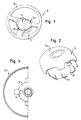
- FIG. 1 shows a steering wheel 10 with an airbag module 12 according to the invention shown.
- the gas bag module 12 comprises a module housing with a cover cap 14, which has a front wall 14a facing the driver.
- a gas generator and a gas bag are housed in the module housing.
- Both in the Front wall 14a of the cap 14 (outside of the gas bag outlet unfolded areas) and in the foam 16 of the steering wheel skeleton are provided at certain points outlet openings 18.
- outflow openings 18 provided in the hub portion 20 of the steering wheel 10 through which a Part of the gas can be derived, for. in the interior of the steering wheel hub.
- FIG. 4 shows an example of a gas bag 22 of an inventive Steering wheel 10 shown.
- the gas bag 22 has outflow openings 24 in the area 26 of the inflation mouth, so that a portion of the gas through the in the side wall 14b formed outflow openings 18 can be derived.
- the flow of the discharged gas can within the airbag module 12th or of the steering wheel 10 influenced by suitable guide means targeted become.
- one or more Outflow openings 18 either only in the front wall 14a of the cap 14, only in the side wall 14b of the cap 14, or only in the hub portion 20 of the Steering wheel 10 may be provided, or there may be outflow openings 18 in several be provided the aforementioned component sections / areas.
Landscapes
- Engineering & Computer Science (AREA)
- Mechanical Engineering (AREA)
- Physics & Mathematics (AREA)
- Fluid Mechanics (AREA)
- Air Bags (AREA)
- Steering Controls (AREA)
Abstract
Description
- Figur 1 eine perspektivische Ansicht eines erfindungsgemäßen Lenkrads mit einem Gassackmodul;
- Figur 2 eine perspektivische Ansicht einer Gassackmodul-Abdeckkappe eines erfindungsgemäßen Lenkrads;
- Figur 3a eine Draufsicht auf ein erfindungsgemäßes Lenkrad ohne Gassackmodul;
- Figur 3b eine schematische Seitenansicht des Lenkrads aus Figur 3a mit Gassackmodul; und
- Figur 4 eine Draufsicht auf einen Gassack eines erfindungsgemäßen Lenkrads.
Claims (7)
- Lenkrad für ein Kraftfahrzeug, mit einem Gassackmodul (12), das ein Modulgehäuse mit einer Abdeckkappe (14) sowie einen Gasgenerator und einen Gassack (22) umfaßt, dadurch gekennzeichnet, daß wenigstens eine Abströmöffnung (18) zum Ableiten des vom Gasgenerator erzeugten und in den Gassack (22) eingeleiteten Gases in der Abdeckkappe (14) vorgesehen ist.
- Lenkrad nach Anspruch 1, dadurch gekennzeichnet, daß die Abströmöffnung (18) in einer dem Fahrer zugewandten Vorderwand (14a) der Abdeckkappe (14) angeordnet ist.
- Lenkrad nach Anspruch 1, dadurch gekennzeichnet, daß die Abströmöffnung (18) in einer Seitenwand (14b) der Abdeckkappe (14) angeordnet ist.
- Lenkrad nach Anspruch 3, dadurch gekennzeichnet, daß der Gassack (22) Ausströmöffnungen (24) im Bereich (26) des Einblasmunds des Gassacks (22) aufweist.
- Lenkrad für ein Kraftfahrzeug, mit einem Lenkradskelett, das von einer Umschäumung (16) umgeben ist, und einem Gassackmodul (12), das einen Gasgenerator und einen Gassack umfaßt, dadurch gekennzeichnet, daß wenigstens eine Abströmöffnung (18) zum Ableiten des vom Gasgenerator erzeugten und in den Gassack eingeleiteten Gases in der Umschäumung (16) vorgesehen ist.
- Lenkrad für ein Kraftfahrzeug mit einer Lenkradnabe und einem Gassackmodul (12), das einen Gasgenerator und einen Gassack umfaßt, dadurch gekennzeichnet, daß wenigstens eine Abströmöffnung (18) zum Ableiten des vom Gasgenerator erzeugten und in den Gassack (22) eingeleiteten Gases im Nabenbereich (20) des Lenkrads vorgesehen ist.
- Lenkrad nach einem der vorhergehenden Ansprüche, dadurch gekennzeichnet, daß das durch die Abströmöffnung (18) austretende Gas zumindest teilweise in das Innere des Gassackmoduls (12) abgeleitet wird.
Applications Claiming Priority (2)
| Application Number | Priority Date | Filing Date | Title |
|---|---|---|---|
| DE202004003464U | 2004-03-05 | ||
| DE202004003464U DE202004003464U1 (de) | 2004-03-05 | 2004-03-05 | Lenkrad für ein Kraftfahrzeug mit einem Gassackmodul |
Publications (3)
| Publication Number | Publication Date |
|---|---|
| EP1571052A2 true EP1571052A2 (de) | 2005-09-07 |
| EP1571052A3 EP1571052A3 (de) | 2006-08-02 |
| EP1571052B1 EP1571052B1 (de) | 2008-09-17 |
Family
ID=34745556
Family Applications (1)
| Application Number | Title | Priority Date | Filing Date |
|---|---|---|---|
| EP05004435A Expired - Lifetime EP1571052B1 (de) | 2004-03-05 | 2005-03-01 | Lenkrad für ein Kraftfahrzeug mit einem Gassackmodul |
Country Status (4)
| Country | Link |
|---|---|
| US (1) | US7731228B2 (de) |
| EP (1) | EP1571052B1 (de) |
| DE (2) | DE202004003464U1 (de) |
| ES (1) | ES2313135T3 (de) |
Citations (4)
| Publication number | Priority date | Publication date | Assignee | Title |
|---|---|---|---|---|
| EP0614787A1 (de) | 1993-03-12 | 1994-09-14 | TRW Occupant Restraint Systems GmbH | Fahrerseitiges Gassack-Rückhaltesystem für Fahrzeuge |
| DE29906477U1 (de) | 1999-04-06 | 1999-08-12 | Petri Ag, 63743 Aschaffenburg | Airbageinheit |
| DE10032791A1 (de) | 2000-06-28 | 2002-01-24 | Takata Petri Ag | Airbagmodul |
| DE20107297U1 (de) | 2001-04-23 | 2002-09-05 | TAKATA-PETRI AG, 63743 Aschaffenburg | Airbagmodul |
Family Cites Families (10)
| Publication number | Priority date | Publication date | Assignee | Title |
|---|---|---|---|---|
| DE2120173A1 (de) * | 1971-04-24 | 1972-11-09 | Volkswagenwerk Ag, 3180 Wolfsburg | Sicherheitsvorrichtung für Fahrzeuge |
| JPS5146932B2 (de) * | 1972-02-29 | 1976-12-11 | ||
| DE4226101A1 (de) * | 1992-08-07 | 1994-02-10 | Pars Passive Rueckhaltesysteme | Lenkung für Kraftfahrzeuge |
| US6082765A (en) * | 1998-11-10 | 2000-07-04 | Trw Vehicle Safety Systems Inc. | Air bag module with fluid venting |
| US6547274B2 (en) * | 2000-02-07 | 2003-04-15 | Honda Giken Kogyo Kabushiki Kaisha | Air bag device |
| US6357791B1 (en) * | 2000-06-22 | 2002-03-19 | Trw Occupant Restraint Systems Gmbh & Co. Kg | Air bag module with vent |
| JP4759867B2 (ja) | 2001-07-25 | 2011-08-31 | タカタ株式会社 | エアバッグ装置 |
| DE10152624A1 (de) * | 2001-10-25 | 2003-05-15 | Breed Automotive Tech | Hupentechnik für ein Airbagmodul |
| US6832778B2 (en) * | 2002-07-19 | 2004-12-21 | Delphi Technologies, Inc. | Air bag restraint including selectively operable venting elements |
| JP3933547B2 (ja) | 2002-08-30 | 2007-06-20 | 本田技研工業株式会社 | エアバッグ装置およびエアバッグ装置の展開方法 |
-
2004
- 2004-03-05 DE DE202004003464U patent/DE202004003464U1/de not_active Expired - Lifetime
-
2005
- 2005-03-01 ES ES05004435T patent/ES2313135T3/es not_active Expired - Lifetime
- 2005-03-01 DE DE502005005370T patent/DE502005005370D1/de not_active Expired - Lifetime
- 2005-03-01 EP EP05004435A patent/EP1571052B1/de not_active Expired - Lifetime
- 2005-03-04 US US11/072,841 patent/US7731228B2/en active Active
Patent Citations (4)
| Publication number | Priority date | Publication date | Assignee | Title |
|---|---|---|---|---|
| EP0614787A1 (de) | 1993-03-12 | 1994-09-14 | TRW Occupant Restraint Systems GmbH | Fahrerseitiges Gassack-Rückhaltesystem für Fahrzeuge |
| DE29906477U1 (de) | 1999-04-06 | 1999-08-12 | Petri Ag, 63743 Aschaffenburg | Airbageinheit |
| DE10032791A1 (de) | 2000-06-28 | 2002-01-24 | Takata Petri Ag | Airbagmodul |
| DE20107297U1 (de) | 2001-04-23 | 2002-09-05 | TAKATA-PETRI AG, 63743 Aschaffenburg | Airbagmodul |
Also Published As
| Publication number | Publication date |
|---|---|
| ES2313135T3 (es) | 2009-03-01 |
| EP1571052B1 (de) | 2008-09-17 |
| DE502005005370D1 (de) | 2008-10-30 |
| US20050194770A1 (en) | 2005-09-08 |
| EP1571052A3 (de) | 2006-08-02 |
| US7731228B2 (en) | 2010-06-08 |
| DE202004003464U1 (de) | 2005-07-14 |
Similar Documents
| Publication | Publication Date | Title |
|---|---|---|
| EP1013514B2 (de) | Luftsack | |
| DE68909027T2 (de) | Airbagmodul und sein Herstellungsverfahren. | |
| DE4418582C2 (de) | Instrumententafel in einem Kraftwagen | |
| DE3422263A1 (de) | Sicherheitseinrichtung zum schutz von fahrzeuginsassen bei einem seitenaufprall | |
| EP0932526B1 (de) | Verfahren zur sicherung eines fahrzeuginsassen und airbagmodul zur durchführung des verfahrens | |
| DE20023347U1 (de) | In ein Innenverkleidungsteil für Kraftfahrzeuge integriertes Airbag-System | |
| EP2662230A1 (de) | Batteriegehäuse | |
| DE19750945C2 (de) | Seitenaufprallschutzmodul zur Montage an einem Sitz eines Kraftfahrzeugs | |
| EP1506899B1 (de) | Fahrzeuginsassen-Rückhaltesystem | |
| DE102014100550B4 (de) | Produkt, das ein Fahrzeug mit einem Dachrahmen-Airbag umfasst | |
| EP1412232B1 (de) | Insassenrückhaltesystem im fondbereich eines kraftfahrzeugs | |
| DE19745872B4 (de) | Airbageinrichtung | |
| EP1324900B1 (de) | Gehäuse für einen aufblasbaren gassack eines kraftfahrzeuges | |
| EP1607279A1 (de) | Schutzvorrichtung für den Fahrer eines Kraftfahrzeugs | |
| EP0952044B1 (de) | Gassack-Modul für ein Fahrzeuginsassen- Rückhaltesystem und Verfahren zu seiner Herstellung | |
| EP0686531A1 (de) | Gassack-Aufprallschutz-Einrichtung | |
| DE102019134482B4 (de) | Luftsack für eine Airbaganordnung und Airbaganorndung eines Fahrzeugsitzes | |
| EP1201510A1 (de) | Sicherheitsvorrichtung für Kraftfahrzeuge | |
| DE102019129912A1 (de) | Gassackanordnung für ein Fahrzeuginsassen-Rückhaltesystem und Verfahren zum Schützen eines Fahrzeuginsassen | |
| EP1571052B1 (de) | Lenkrad für ein Kraftfahrzeug mit einem Gassackmodul | |
| DE19737744A1 (de) | Lenkvorrichtung eines Fahrzeugs | |
| EP2176096B1 (de) | Airbagmodul für ein kraftfahrzeug | |
| EP1588920A1 (de) | Energie absorbierendes Lenkrad | |
| EP0876266A1 (de) | Vorrichtung zum schutz von insassen eines kfz | |
| EP1088711B1 (de) | Beifahrer-Airbagmodul für Kraftfahrzeuge |
Legal Events
| Date | Code | Title | Description |
|---|---|---|---|
| PUAI | Public reference made under article 153(3) epc to a published international application that has entered the european phase |
Free format text: ORIGINAL CODE: 0009012 |
|
| AK | Designated contracting states |
Kind code of ref document: A2 Designated state(s): AT BE BG CH CY CZ DE DK EE ES FI FR GB GR HU IE IS IT LI LT LU MC NL PL PT RO SE SI SK TR |
|
| AX | Request for extension of the european patent |
Extension state: AL BA HR LV MK YU |
|
| PUAL | Search report despatched |
Free format text: ORIGINAL CODE: 0009013 |
|
| AK | Designated contracting states |
Kind code of ref document: A3 Designated state(s): AT BE BG CH CY CZ DE DK EE ES FI FR GB GR HU IE IS IT LI LT LU MC NL PL PT RO SE SI SK TR |
|
| AX | Request for extension of the european patent |
Extension state: AL BA HR LV MK YU |
|
| 17P | Request for examination filed |
Effective date: 20070129 |
|
| AKX | Designation fees paid |
Designated state(s): DE ES FR IT |
|
| GRAP | Despatch of communication of intention to grant a patent |
Free format text: ORIGINAL CODE: EPIDOSNIGR1 |
|
| RIC1 | Information provided on ipc code assigned before grant |
Ipc: B60R 21/203 20060101ALI20080505BHEP Ipc: B60R 21/276 20060101AFI20080505BHEP |
|
| GRAS | Grant fee paid |
Free format text: ORIGINAL CODE: EPIDOSNIGR3 |
|
| GRAA | (expected) grant |
Free format text: ORIGINAL CODE: 0009210 |
|
| AK | Designated contracting states |
Kind code of ref document: B1 Designated state(s): DE ES FR IT |
|
| REF | Corresponds to: |
Ref document number: 502005005370 Country of ref document: DE Date of ref document: 20081030 Kind code of ref document: P |
|
| REG | Reference to a national code |
Ref country code: ES Ref legal event code: FG2A Ref document number: 2313135 Country of ref document: ES Kind code of ref document: T3 |
|
| PGFP | Annual fee paid to national office [announced via postgrant information from national office to epo] |
Ref country code: ES Payment date: 20090323 Year of fee payment: 5 |
|
| PLBE | No opposition filed within time limit |
Free format text: ORIGINAL CODE: 0009261 |
|
| STAA | Information on the status of an ep patent application or granted ep patent |
Free format text: STATUS: NO OPPOSITION FILED WITHIN TIME LIMIT |
|
| 26N | No opposition filed |
Effective date: 20090618 |
|
| REG | Reference to a national code |
Ref country code: ES Ref legal event code: FD2A Effective date: 20110415 |
|
| PG25 | Lapsed in a contracting state [announced via postgrant information from national office to epo] |
Ref country code: ES Free format text: LAPSE BECAUSE OF NON-PAYMENT OF DUE FEES Effective date: 20110404 |
|
| PG25 | Lapsed in a contracting state [announced via postgrant information from national office to epo] |
Ref country code: ES Free format text: LAPSE BECAUSE OF NON-PAYMENT OF DUE FEES Effective date: 20100302 |
|
| PGFP | Annual fee paid to national office [announced via postgrant information from national office to epo] |
Ref country code: IT Payment date: 20120323 Year of fee payment: 8 |
|
| PG25 | Lapsed in a contracting state [announced via postgrant information from national office to epo] |
Ref country code: IT Free format text: LAPSE BECAUSE OF NON-PAYMENT OF DUE FEES Effective date: 20130301 |
|
| REG | Reference to a national code |
Ref country code: FR Ref legal event code: PLFP Year of fee payment: 12 |
|
| REG | Reference to a national code |
Ref country code: FR Ref legal event code: PLFP Year of fee payment: 13 |
|
| REG | Reference to a national code |
Ref country code: FR Ref legal event code: PLFP Year of fee payment: 14 |
|
| PGFP | Annual fee paid to national office [announced via postgrant information from national office to epo] |
Ref country code: DE Payment date: 20180331 Year of fee payment: 14 |
|
| PGFP | Annual fee paid to national office [announced via postgrant information from national office to epo] |
Ref country code: FR Payment date: 20190325 Year of fee payment: 15 |
|
| REG | Reference to a national code |
Ref country code: DE Ref legal event code: R119 Ref document number: 502005005370 Country of ref document: DE |
|
| PG25 | Lapsed in a contracting state [announced via postgrant information from national office to epo] |
Ref country code: DE Free format text: LAPSE BECAUSE OF NON-PAYMENT OF DUE FEES Effective date: 20191001 |
|
| PG25 | Lapsed in a contracting state [announced via postgrant information from national office to epo] |
Ref country code: FR Free format text: LAPSE BECAUSE OF NON-PAYMENT OF DUE FEES Effective date: 20200331 |