EP1570828B1 - Elément de massage - Google Patents
Elément de massage Download PDFInfo
- Publication number
- EP1570828B1 EP1570828B1 EP20050101491 EP05101491A EP1570828B1 EP 1570828 B1 EP1570828 B1 EP 1570828B1 EP 20050101491 EP20050101491 EP 20050101491 EP 05101491 A EP05101491 A EP 05101491A EP 1570828 B1 EP1570828 B1 EP 1570828B1
- Authority
- EP
- European Patent Office
- Prior art keywords
- massage
- abutment
- balls
- cage
- attachment
- Prior art date
- Legal status (The legal status is an assumption and is not a legal conclusion. Google has not performed a legal analysis and makes no representation as to the accuracy of the status listed.)
- Expired - Lifetime
Links
- 230000008878 coupling Effects 0.000 claims description 11
- 238000010168 coupling process Methods 0.000 claims description 11
- 238000005859 coupling reaction Methods 0.000 claims description 11
- 230000000717 retained effect Effects 0.000 claims 3
- 229910000831 Steel Inorganic materials 0.000 claims 1
- 239000010959 steel Substances 0.000 claims 1
- 239000007788 liquid Substances 0.000 description 4
- 239000000463 material Substances 0.000 description 3
- 230000015572 biosynthetic process Effects 0.000 description 2
- 238000009434 installation Methods 0.000 description 2
- 238000004519 manufacturing process Methods 0.000 description 2
- 229910001220 stainless steel Inorganic materials 0.000 description 2
- 239000010935 stainless steel Substances 0.000 description 2
- 230000000295 complement effect Effects 0.000 description 1
- -1 for example Substances 0.000 description 1
- 239000002991 molded plastic Substances 0.000 description 1
- 239000004033 plastic Substances 0.000 description 1
Images
Classifications
-
- A—HUMAN NECESSITIES
- A61—MEDICAL OR VETERINARY SCIENCE; HYGIENE
- A61H—PHYSICAL THERAPY APPARATUS, e.g. DEVICES FOR LOCATING OR STIMULATING REFLEX POINTS IN THE BODY; ARTIFICIAL RESPIRATION; MASSAGE; BATHING DEVICES FOR SPECIAL THERAPEUTIC OR HYGIENIC PURPOSES OR SPECIFIC PARTS OF THE BODY
- A61H15/00—Massage by means of rollers, balls, e.g. inflatable, chains, or roller chains
- A61H15/0078—Massage by means of rollers, balls, e.g. inflatable, chains, or roller chains power-driven
-
- A—HUMAN NECESSITIES
- A61—MEDICAL OR VETERINARY SCIENCE; HYGIENE
- A61H—PHYSICAL THERAPY APPARATUS, e.g. DEVICES FOR LOCATING OR STIMULATING REFLEX POINTS IN THE BODY; ARTIFICIAL RESPIRATION; MASSAGE; BATHING DEVICES FOR SPECIAL THERAPEUTIC OR HYGIENIC PURPOSES OR SPECIFIC PARTS OF THE BODY
- A61H35/00—Baths for specific parts of the body
- A61H35/006—Baths for specific parts of the body for the feet
Definitions
- the invention relates to a massage attachment for a foot care device having a plurality of spherical massage bodies and having a coupling portion for torque-locking connection of the attachment to the movement of a motor-driven drive shaft of seldomnostimonyes, the spherical massage body freely rotatable, each received in a cage of the essay and with a section the cage outstanding body, in particular balls are supported on the underside of an abutment, by which the massage balls are held in their treatment with a section of the cage treatment outstanding position.
- Massage attachments for foot care devices may have spherical massage bodies as massage elements.
- these spherical massage bodies are either spherical or knob-like projections of the massage attachment or even mounted in the massage attachment balls.
- the balls have diametrically opposite and integrally formed on the ball stub axles, which are mounted in the massage attachment.
- These massage balls are then rotatable about the axis of the stub axles.
- the latter massage attachments with the rotatably mounted massage balls are used for foot care devices, which have a motor-driven drive shaft, on the free end of this or another massage attachment is torque-attachable. By the drive shaft, the massage attachment is rotatably driven.
- the axes of rotation of the massage balls are aligned in the radial direction, so that the balls make the rotational movement of the essay with, but by the possible opposite rotational movement to the rotational movement, the friction on the sole to be massaged low hold, at least as long as the foot remains in one and the same position on the massage attachment.
- a proper movement of the sole of the foot on the massage balls can be achieved through the massage balls
- such a prior art massage essay can not be compensated.
- the installation of such a massage attachment is cumbersome because each massage ball must be used in their intended position with their thru axles in a bearing mount.
- the massage balls themselves are injection-molded plastic parts, since with this manufacturing process, the uncomplicated geometry of the balls provided with stub axles can be realized without further ado. However, this has the disadvantage that only with an unacceptably high cost massage balls can be used from other materials.
- WO 99/59516 A1 discloses a massage apparatus having a massage head in which a plurality of massage balls are accommodated.
- the massage balls are each encapsulated in a separate ball holder.
- the massage balls protrude with a section sticking out.
- the massage balls receiving insert which in turn is typically used in the massage head, be addressed as a cage.
- the massage head of this aforementioned massager does not have an abutment against which the massage balls are supported.
- WO 94/04116 A1 describes a multipurpose steam generator equipped with means for distributing a liquid in the area of the surface to be treated.
- This device ultimately serves as a massage or massage assistive device.
- the liquid distribution device has a head in which a plurality of balls are rotatably mounted.
- the head is constructed in two parts, with its outer shell serving circular openings for passing a portion of the balls provided for the liquid distribution.
- These balls are supported on the back on a plate for closing the cavity in which the balls are arranged from.
- this plate forms an abutment for the balls so that they are held in their outstanding position by the openings of the other element of the head.
- this multipurpose steam generator is not suitable for an intensive massage, in particular not one that is to be carried out with a certain pressure on the surface to be treated.
- the invention is therefore the object of developing an aforementioned massage essay in such a way that not only its installation is facilitated, but also that also with this intensive massages can be performed with a higher contact pressure.
- each cage associated abutment is formed by a projecting from a common abutment plate towards the cage abutment extension, of which at least some abutment extensions in their associated cage intervention.
- the spherical massage body in each case a cage are free and thus rotatably received in any direction.
- the massage balls are inserted in their respective cage in such a way that they protrude from the cage with a section on the treatment side.
- the provision of massage balls and their freely rotatable arrangement in a cage has the consequence that even movements of the foot can be compensated by the balls without such a movement of the foot on the massage attachment perceived as unpleasant friction is noticeable.
- balls are used as the massage body, which are not only inexpensive to manufacture, but also can be easily mounted, since they are to be introduced regardless of a predetermined orientation in the cage. Above all, the massage balls can be made of different materials, for example, stainless steel in this massage essay.
- the abutment is formed by an abutment plate. This has in the direction of the cage projecting abutment extensions, which support the massage body. At least some of these infiltrate the cages.
- the abutment extensions can be designed for example as cross ribs.
- the intervention of at least some abutment extensions in the cages is used in addition to the provision of the lower abutment for the balls and the closure of the cages and for producing a torque-locking connection of the abutment plate with the cages-carrying shell of the massage attachment. This is expedient in an embodiment in which on the abutment plate on the underside protruding the coupling portion is formed, with which the massage attachment is ceremonistecken on the free end of the drive shaft of a montician experts.
- the cages receiving the massage balls are annular cylindrical sections, formed on a shell of the massage attachment. It is expediently provided to design the upper opening tapered by an inwardly projecting flange, wherein the inside width of this taper is smaller than the diameter of the held in this cage massage ball. This ensures that the massage balls on the treatment side can not escape from the cage.
- an abutment plate on which the balls are supported on the underside. The abutment plate expediently forms the lower closure of the massage attachment and can be held on it by appropriately designed latching connection elements.
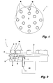
- a massage attachment 1 for a foot care device comprises as massage body several massage balls M, the treatment side with a section each of a cage K and in the representation of FIG. 2 protruding from the top.
- the massage attachment 1 is circular in plan view and comprises an upper convexly curved shell 2, on which the cages K are formed (see FIG. FIG. 2 ).
- the massage balls M which are stainless steel balls in the illustrated embodiment, are held captive in a respective cage K.
- the cages K are formed from an annular cylindrical body 3, which protrudes from the convex upper side of the shell 2.
- the upper terminations of the annular cylindrical body 3 are in the illustrated embodiment in a common plane.
- the annular cylindrical body 3 have at its upper opening on an inwardly projecting flange 4, through which the inside diameter of the opening is kept smaller than the diameter of the body 3 enclosed massage ball M.
- the upper shell 2 of the massage attachment 1 carries inside several locking elements. These locking elements are on a downwardly projecting circumferential collar 5 of the shell 2 internally formed locking lugs 6 and two or more each with the same angular distance from each other arranged from the bottom of the shell 2 downwardly projecting locking projections 7.
- the locking elements 6, 7 serve to hold an abutment plate 8, on which each cage K associated abutment extension 9 is formed projecting upwards.
- the abutment extensions 9 shown in the illustrated embodiment are designed in the manner of cross ribs. The upper end of the abutment extensions 9 is based on the upper end of the body 3 in such a height that the massage balls M contained in the cages K are pushed out with a portion of the upper opening of the cages K.
- the abutment extensions 9 form the lower closure of the cages K, so that the massage balls M are captive enclosed in the cages K.
- the abutment plate 8 engages in the in FIG. 2 shown mounted position, the locking lugs 6 and the hook portion of the latching projections 7, so that the abutment plate 8 forms an objective unit with the shell 2 with the abutment extensions 9.
- the locking lugs 6 engage behind the abutment plate 8 as well as the hook element of the latching projections 7, which are brought through an opening in the abutment plate 8 engages behind position.
- the shell 8 is made of plastic, so that for the mounting of the abutment plate 8, the material elastic properties of the shell 2 and thus also the locking elements 6, 7 are used.
- the massage balls M are freely rotatably mounted in their respective cages K.
- the massage balls M have, in particular, no axle extensions, by means of which the rotatability of the massage balls would be limited around an axis of rotation. Rather, the massage balls M allow a massage, for example, the sole of the foot by a rotating drive of the massage attachment 1 and a compensation of a simultaneous proper movement of the sole on the massage attachment 1. Therefore, with the massage attachment 1 a particularly pleasant massage, for example, the sole of the foot can be made.
- the described massage attachment 1 is particularly easy to install.
- the required massage balls M are inserted into the body 3 of the cages K.
- the abutment plate 8 is inserted into the shell 2 and latched to the locking elements 6, 7.
- the cages K are underside by the abutment extensions 9 closed.
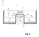
- FIG. 3 shows a foot care device 12 comprising a foot bath 13, which is divided by a web 14 into two sub-baths 15, 15 '.
- the partial baths 15, 15 ' can, as shown, be filled with liquid.
- the bottom of the sub-baths 15, 15 ' are each covered with an insert 16, 16', which serves to massage the soles of a user.
- the web 14 carries a foot care device designated overall by the reference numeral 17, which comprises an electric motor 18, a drive shaft 19 and the massage attachment 1 of FIG Figures 1 and 2 includes. For the sake of clarity, further required components, such as electrical switches or the like, are not shown.
- the electric motor 18 is secured against rotation in the cavity 20 formed by the web 14.
- a coupling piece 21 At the upper end of the drive shaft 19 is a coupling piece 21, the radial outer side is complementary to the formation of the inside of the coupling portion 10 of the massage attachment 1 is formed.
- the massage attachment 1 is detachably connected with its coupling portion 10 to the drive shaft 19 and can be easily replaced in this way against another essay.
- FIG. 3 the article 1 is shown in its non-operating position.
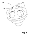
- FIG. 4 shows a further massage attachment 22, whose upper side is formed hemispherical.
- the convex configuration of the shell 23 of the massage attachment 22 is emphasized over the massage attachment 1.
- the individual massage balls M are held directly by the shell 23.
- the openings of the shell 23, from which the massage balls M protrude in part, are smaller in diameter than the diameter of the massage balls M.
- the edge of the openings of the shell 23 pointing into the interior of the massage attachment 22 carries a chamfer, optionally with one to the curvature Massage balls M complete curvature.
- the massage balls M of the massage attachment 22 are supported on the underside on an abutment, through which the massage balls M in their in FIG. 3 shown, are held out of the shell 23 outstanding position.
- a single correspondingly shaped abutment is provided to support all massage balls M. It can also be provided to associate each massage ball M of the massage attachment 22 with its own abutment.
- the cage is thus formed by the openings of the shell 23 delimiting areas of the shell 23 and the one or more abutments that hold each massage ball in its intended position.
- the massage balls M are based directly on the abutments described or from.
- the abutment has a certain flexibility or between the abutment and the massage balls a resilient element, such as a spring element is arranged.
- a resilient element such as a spring element is arranged.
- one will design such compliance in a manner that the massage balls can only be pressed by a small amount in their respective cage of the massage attachment. In such a conception, care will be taken that the massage balls held in the respective cage can roll.
- the massage attachment comprises differently sized massage balls.
Landscapes
- Health & Medical Sciences (AREA)
- Epidemiology (AREA)
- Pain & Pain Management (AREA)
- Physical Education & Sports Medicine (AREA)
- Rehabilitation Therapy (AREA)
- Life Sciences & Earth Sciences (AREA)
- Animal Behavior & Ethology (AREA)
- General Health & Medical Sciences (AREA)
- Public Health (AREA)
- Veterinary Medicine (AREA)
- Massaging Devices (AREA)
- Finger-Pressure Massage (AREA)
Claims (7)
- Elément de massage pour un appareil de soin des pieds (17) comportant plusieurs corps de massage (M) en forme de bille et comportant un tronçon de couplage (10) afin de raccorder, de manière solidaire en rotation, un élément (1) au mouvement d'un arbre d'entraînement (19) entraîné de façon motorisée de l'appareil de soin des pieds (17), les corps de massage (M) en forme de bille étant des corps, notamment des billes, qui tournent librement dont un tronçon dépasse de la cage (K), qui s'appuient sur la face inférieure sur un support (8,9), par lequel les corps de massage (M) en forme de bille sont maintenus dans leur position où l'un de leurs tronçons dépasse de la cage (K) du côté où se fait le traitement, caractérisé en ce que le support affecté à chaque cage (K) est formé par un pilier-support (9) qui dépasse d'un plateau-support (8) commun orienté vers la cage (K), dont au moins quelques piliers-support (9) s'engagent dans la cage (K) qui leur est affectée.
- Elément de massage selon la revendication 1 caractérisé en ce que les cages (K) sont chacune formées par un corps cylindrique annulaire, dont l'ouverture supérieure est rétrécie par une bride (4) en saillie vers l'intérieur, la largeur nette du rétrécissement étant plus petite que le diamètre de chaque bille (M) maintenue dans une cage.
- Elément de massage selon la revendication 1 caractérisé en ce que les piliers-support (9) sont conformés en croix.
- Elément de massage selon la revendication 1 caractérisé en ce que le tronçon de couplage (10) est moulé sur le plateau-support (8) qui supporte les piliers-support (9).
- Elément de massage selon l'une des revendications 1 à 4 caractérisé en ce que les corps (3) formant les cages font partie d'une coque (2) extérieure comportant, disposés sur la face intérieure, des éléments d'enclenchement (6,7) contre lesquels est maintenu le support prévu pour les billes de massage (M).
- Elément de massage selon l'une des revendications 1 à 5 caractérisé en ce que les cages (K) sont fermées sur la face inférieure par le support qui évite que les billes de massage (M) n'en tombent.
- Elément de massage selon l'une des revendications 1 à 6 caractérisé en ce que les billes de massage (M) sont des billes d'acier inoxydables.
Applications Claiming Priority (2)
| Application Number | Priority Date | Filing Date | Title |
|---|---|---|---|
| DE202004003430U | 2004-03-05 | ||
| DE200420003430 DE202004003430U1 (de) | 2004-03-05 | 2004-03-05 | Massageaufsatz |
Publications (3)
| Publication Number | Publication Date |
|---|---|
| EP1570828A2 EP1570828A2 (fr) | 2005-09-07 |
| EP1570828A3 EP1570828A3 (fr) | 2006-04-12 |
| EP1570828B1 true EP1570828B1 (fr) | 2008-07-16 |
Family
ID=34745553
Family Applications (1)
| Application Number | Title | Priority Date | Filing Date |
|---|---|---|---|
| EP20050101491 Expired - Lifetime EP1570828B1 (fr) | 2004-03-05 | 2005-02-28 | Elément de massage |
Country Status (5)
| Country | Link |
|---|---|
| EP (1) | EP1570828B1 (fr) |
| CN (1) | CN2770636Y (fr) |
| DE (2) | DE202004003430U1 (fr) |
| ES (1) | ES2309655T3 (fr) |
| HK (1) | HK1072151A2 (fr) |
Families Citing this family (2)
| Publication number | Priority date | Publication date | Assignee | Title |
|---|---|---|---|---|
| CN110193136B (zh) * | 2018-02-26 | 2022-11-04 | 苏州纳通生物纳米技术有限公司 | 一种纳米晶片促渗仪 |
| CN108498302A (zh) * | 2018-04-19 | 2018-09-07 | 张艳 | 一种万向轮按摩机械手 |
Family Cites Families (7)
| Publication number | Priority date | Publication date | Assignee | Title |
|---|---|---|---|---|
| DE2238563C2 (de) * | 1972-08-04 | 1974-04-11 | Fa. Heinrich Schaefer, 5620 Velbert | Massagegerät |
| US3994290A (en) * | 1975-09-29 | 1976-11-30 | Clairol Incorporated | Massage device |
| CA2014070A1 (fr) * | 1990-04-06 | 1991-10-06 | Leatherjet Inc. | Dispositif servant a faire penetrer un produit de traitement dans une surface |
| EP0654987A4 (fr) * | 1992-08-17 | 1995-12-13 | Mehl Thomas L | Dispositif a main, portatif et polyvalent, produisant de la vapeur. |
| DE19818745A1 (de) * | 1998-04-27 | 1999-10-28 | Consolidated Market Alliance C | Bademassagegerät |
| AU3531499A (en) * | 1998-05-19 | 1999-12-06 | Rovinelli Bruno S.R.L. | Apparatus for superficial or deep massage of the human body |
| CN2446983Y (zh) * | 2000-07-25 | 2001-09-12 | 建福实业有限公司 | 多功能足部按摩器 |
-
2004
- 2004-03-05 DE DE200420003430 patent/DE202004003430U1/de not_active Expired - Lifetime
-
2005
- 2005-02-28 EP EP20050101491 patent/EP1570828B1/fr not_active Expired - Lifetime
- 2005-02-28 DE DE200550004692 patent/DE502005004692D1/de not_active Expired - Lifetime
- 2005-02-28 ES ES05101491T patent/ES2309655T3/es not_active Expired - Lifetime
- 2005-03-04 HK HK05101883A patent/HK1072151A2/xx not_active IP Right Cessation
- 2005-03-04 CN CNU2005200053912U patent/CN2770636Y/zh not_active Expired - Fee Related
Also Published As
| Publication number | Publication date |
|---|---|
| EP1570828A2 (fr) | 2005-09-07 |
| ES2309655T3 (es) | 2008-12-16 |
| EP1570828A3 (fr) | 2006-04-12 |
| HK1072151A2 (en) | 2005-08-12 |
| DE502005004692D1 (de) | 2008-08-28 |
| DE202004003430U1 (de) | 2005-07-21 |
| CN2770636Y (zh) | 2006-04-12 |
Similar Documents
| Publication | Publication Date | Title |
|---|---|---|
| DE60022843T2 (de) | Knöchelprothese | |
| DE2160561A1 (de) | Vorrichtung zum behandeln der atmungswege mit warmluft | |
| DE20200790U1 (de) | Massageaufsatz für ein motorisch angetriebenes Fußpflegegerät | |
| CH507704A (de) | Schenkelkopfprothese | |
| DE4330248A1 (de) | Gelenkprothese | |
| EP2674085B1 (fr) | Brosse WC | |
| EP0142759A2 (fr) | Cuvette d'articulation de la hanche | |
| DE19652232A1 (de) | Muttermilchpumpe und Ventil hierfür | |
| DE202022104964U1 (de) | Vorrichtung für eine Zahnbürste und Zahnbürste | |
| EP1570828B1 (fr) | Elément de massage | |
| EP2349112B1 (fr) | Implant | |
| DE202007004726U1 (de) | Mehrfach konfigurierbarer Duschkopf | |
| EP2769680A1 (fr) | Dispositif de libération pour libérer un implant médical d'un dispositif d'introduction ainsi que dispositif d'introduction avec dispositif de libération | |
| EP2329806A1 (fr) | Dispositif de massage | |
| EP4216898B1 (fr) | Appareil d'exercice | |
| AT524655B1 (de) | Vorrichtung zur nichtinvasiven Trichterbrustkorrektur | |
| DE19520495C1 (de) | Künstliche Hüftgelenkpfanne | |
| DE20018382U1 (de) | Vorrichtung zum massierenden Behandeln der Körperoberfläche | |
| CH664486A5 (en) | Self massage appliance - has rollers with interchangeable sleeves for producing different therapeutic effects | |
| DE19601779A1 (de) | Bürstenelement für ein Massagegerät | |
| EP3513771B1 (fr) | Dispositif d'entraînement pour corps caverneux | |
| DE4332104C2 (de) | Massagegerät | |
| DE10129993C2 (de) | Zwischenwirbel-Implantat | |
| DE3822170A1 (de) | Luftverteiler-unterlage fuer eine sprudel-badeeinrichtung | |
| DE3135529A1 (de) | Vorrichtung zum spenden von wattekugeln |
Legal Events
| Date | Code | Title | Description |
|---|---|---|---|
| PUAI | Public reference made under article 153(3) epc to a published international application that has entered the european phase |
Free format text: ORIGINAL CODE: 0009012 |
|
| AK | Designated contracting states |
Kind code of ref document: A2 Designated state(s): AT BE BG CH CY CZ DE DK EE ES FI FR GB GR HU IE IS IT LI LT LU MC NL PL PT RO SE SI SK TR |
|
| AX | Request for extension of the european patent |
Extension state: AL BA HR LV MK YU |
|
| PUAL | Search report despatched |
Free format text: ORIGINAL CODE: 0009013 |
|
| AK | Designated contracting states |
Kind code of ref document: A3 Designated state(s): AT BE BG CH CY CZ DE DK EE ES FI FR GB GR HU IE IS IT LI LT LU MC NL PL PT RO SE SI SK TR |
|
| AX | Request for extension of the european patent |
Extension state: AL BA HR LV MK YU |
|
| 17P | Request for examination filed |
Effective date: 20060522 |
|
| AKX | Designation fees paid |
Designated state(s): CH DE ES FR GB IT LI |
|
| RTI1 | Title (correction) |
Free format text: MASSAGING HEAD |
|
| GRAP | Despatch of communication of intention to grant a patent |
Free format text: ORIGINAL CODE: EPIDOSNIGR1 |
|
| GRAS | Grant fee paid |
Free format text: ORIGINAL CODE: EPIDOSNIGR3 |
|
| GRAA | (expected) grant |
Free format text: ORIGINAL CODE: 0009210 |
|
| AK | Designated contracting states |
Kind code of ref document: B1 Designated state(s): CH DE ES FR GB IT LI |
|
| REG | Reference to a national code |
Ref country code: GB Ref legal event code: FG4D Free format text: NOT ENGLISH |
|
| REG | Reference to a national code |
Ref country code: CH Ref legal event code: NV Representative=s name: PA ALDO ROEMPLER Ref country code: CH Ref legal event code: EP |
|
| REF | Corresponds to: |
Ref document number: 502005004692 Country of ref document: DE Date of ref document: 20080828 Kind code of ref document: P |
|
| REG | Reference to a national code |
Ref country code: CH Ref legal event code: PCAR Free format text: ALDO ROEMPLER PATENTANWALT;BRENDENWEG 11 POSTFACH 154;9424 RHEINECK (CH) |
|
| REG | Reference to a national code |
Ref country code: ES Ref legal event code: FG2A Ref document number: 2309655 Country of ref document: ES Kind code of ref document: T3 |
|
| PLBE | No opposition filed within time limit |
Free format text: ORIGINAL CODE: 0009261 |
|
| STAA | Information on the status of an ep patent application or granted ep patent |
Free format text: STATUS: NO OPPOSITION FILED WITHIN TIME LIMIT |
|
| 26N | No opposition filed |
Effective date: 20090417 |
|
| PGFP | Annual fee paid to national office [announced via postgrant information from national office to epo] |
Ref country code: IT Payment date: 20110225 Year of fee payment: 7 |
|
| PG25 | Lapsed in a contracting state [announced via postgrant information from national office to epo] |
Ref country code: IT Free format text: LAPSE BECAUSE OF NON-PAYMENT OF DUE FEES Effective date: 20120228 |
|
| PGFP | Annual fee paid to national office [announced via postgrant information from national office to epo] |
Ref country code: FR Payment date: 20130315 Year of fee payment: 9 Ref country code: CH Payment date: 20130220 Year of fee payment: 9 Ref country code: GB Payment date: 20130219 Year of fee payment: 9 Ref country code: DE Payment date: 20130121 Year of fee payment: 9 |
|
| PGFP | Annual fee paid to national office [announced via postgrant information from national office to epo] |
Ref country code: ES Payment date: 20120221 Year of fee payment: 8 |
|
| REG | Reference to a national code |
Ref country code: ES Ref legal event code: FD2A Effective date: 20140408 |
|
| PG25 | Lapsed in a contracting state [announced via postgrant information from national office to epo] |
Ref country code: ES Free format text: LAPSE BECAUSE OF NON-PAYMENT OF DUE FEES Effective date: 20130301 |
|
| REG | Reference to a national code |
Ref country code: DE Ref legal event code: R119 Ref document number: 502005004692 Country of ref document: DE |
|
| REG | Reference to a national code |
Ref country code: CH Ref legal event code: PL |
|
| GBPC | Gb: european patent ceased through non-payment of renewal fee |
Effective date: 20140228 |
|
| PG25 | Lapsed in a contracting state [announced via postgrant information from national office to epo] |
Ref country code: LI Free format text: LAPSE BECAUSE OF NON-PAYMENT OF DUE FEES Effective date: 20140228 Ref country code: CH Free format text: LAPSE BECAUSE OF NON-PAYMENT OF DUE FEES Effective date: 20140228 |
|
| REG | Reference to a national code |
Ref country code: FR Ref legal event code: ST Effective date: 20141031 |
|
| REG | Reference to a national code |
Ref country code: DE Ref legal event code: R119 Ref document number: 502005004692 Country of ref document: DE Effective date: 20140902 |
|
| PG25 | Lapsed in a contracting state [announced via postgrant information from national office to epo] |
Ref country code: DE Free format text: LAPSE BECAUSE OF NON-PAYMENT OF DUE FEES Effective date: 20140902 Ref country code: FR Free format text: LAPSE BECAUSE OF NON-PAYMENT OF DUE FEES Effective date: 20140228 Ref country code: GB Free format text: LAPSE BECAUSE OF NON-PAYMENT OF DUE FEES Effective date: 20140228 |