EP1570500B1 - Folientastatur mit mehrschichtiger trägerfolie - Google Patents
Folientastatur mit mehrschichtiger trägerfolie Download PDFInfo
- Publication number
- EP1570500B1 EP1570500B1 EP03812602A EP03812602A EP1570500B1 EP 1570500 B1 EP1570500 B1 EP 1570500B1 EP 03812602 A EP03812602 A EP 03812602A EP 03812602 A EP03812602 A EP 03812602A EP 1570500 B1 EP1570500 B1 EP 1570500B1
- Authority
- EP
- European Patent Office
- Prior art keywords
- foil
- layers
- pressure sensor
- carrier
- layered
- Prior art date
- Legal status (The legal status is an assumption and is not a legal conclusion. Google has not performed a legal analysis and makes no representation as to the accuracy of the status listed.)
- Expired - Lifetime
Links
- 239000011888 foil Substances 0.000 title claims abstract description 128
- 239000000463 material Substances 0.000 claims abstract description 57
- 125000006850 spacer group Chemical group 0.000 claims abstract description 14
- 239000002184 metal Substances 0.000 claims description 12
- 229910052751 metal Inorganic materials 0.000 claims description 12
- 239000000126 substance Substances 0.000 claims description 6
- 239000011347 resin Substances 0.000 claims description 5
- 229920005989 resin Polymers 0.000 claims description 5
- 150000002739 metals Chemical class 0.000 claims description 4
- 239000010410 layer Substances 0.000 description 68
- 239000012790 adhesive layer Substances 0.000 description 8
- 238000000034 method Methods 0.000 description 5
- 239000000853 adhesive Substances 0.000 description 4
- 230000001070 adhesive effect Effects 0.000 description 4
- 230000000694 effects Effects 0.000 description 4
- 239000004033 plastic Substances 0.000 description 3
- 239000002985 plastic film Substances 0.000 description 3
- 238000005316 response function Methods 0.000 description 3
- 239000004065 semiconductor Substances 0.000 description 3
- 230000035945 sensitivity Effects 0.000 description 3
- 239000000758 substrate Substances 0.000 description 3
- 239000011248 coating agent Substances 0.000 description 2
- 238000000576 coating method Methods 0.000 description 2
- 238000007599 discharging Methods 0.000 description 2
- 229920006255 plastic film Polymers 0.000 description 2
- 241001274660 Modulus Species 0.000 description 1
- 238000004458 analytical method Methods 0.000 description 1
- 230000007423 decrease Effects 0.000 description 1
- 230000001419 dependent effect Effects 0.000 description 1
- 238000000151 deposition Methods 0.000 description 1
- 230000005611 electricity Effects 0.000 description 1
- 230000005670 electromagnetic radiation Effects 0.000 description 1
- 238000010030 laminating Methods 0.000 description 1
- 238000003475 lamination Methods 0.000 description 1
- 238000004519 manufacturing process Methods 0.000 description 1
- 229920003223 poly(pyromellitimide-1,4-diphenyl ether) Polymers 0.000 description 1
- 238000007650 screen-printing Methods 0.000 description 1
- 230000003068 static effect Effects 0.000 description 1
- 238000004381 surface treatment Methods 0.000 description 1
Images

Classifications
-
- H—ELECTRICITY
- H01—ELECTRIC ELEMENTS
- H01H—ELECTRIC SWITCHES; RELAYS; SELECTORS; EMERGENCY PROTECTIVE DEVICES
- H01H13/00—Switches having rectilinearly-movable operating part or parts adapted for pushing or pulling in one direction only, e.g. push-button switch
- H01H13/70—Switches having rectilinearly-movable operating part or parts adapted for pushing or pulling in one direction only, e.g. push-button switch having a plurality of operating members associated with different sets of contacts, e.g. keyboard
- H01H13/702—Switches having rectilinearly-movable operating part or parts adapted for pushing or pulling in one direction only, e.g. push-button switch having a plurality of operating members associated with different sets of contacts, e.g. keyboard with contacts carried by or formed from layers in a multilayer structure, e.g. membrane switches
-
- H—ELECTRICITY
- H01—ELECTRIC ELEMENTS
- H01H—ELECTRIC SWITCHES; RELAYS; SELECTORS; EMERGENCY PROTECTIVE DEVICES
- H01H13/00—Switches having rectilinearly-movable operating part or parts adapted for pushing or pulling in one direction only, e.g. push-button switch
- H01H13/70—Switches having rectilinearly-movable operating part or parts adapted for pushing or pulling in one direction only, e.g. push-button switch having a plurality of operating members associated with different sets of contacts, e.g. keyboard
-
- H—ELECTRICITY
- H01—ELECTRIC ELEMENTS
- H01H—ELECTRIC SWITCHES; RELAYS; SELECTORS; EMERGENCY PROTECTIVE DEVICES
- H01H2201/00—Contacts
- H01H2201/022—Material
- H01H2201/032—Conductive polymer; Rubber
- H01H2201/036—Variable resistance
-
- H—ELECTRICITY
- H01—ELECTRIC ELEMENTS
- H01H—ELECTRIC SWITCHES; RELAYS; SELECTORS; EMERGENCY PROTECTIVE DEVICES
- H01H2209/00—Layers
- H01H2209/002—Materials
-
- H—ELECTRICITY
- H01—ELECTRIC ELEMENTS
- H01H—ELECTRIC SWITCHES; RELAYS; SELECTORS; EMERGENCY PROTECTIVE DEVICES
- H01H2209/00—Layers
- H01H2209/014—Layers composed of different layers; Lubricant in between
-
- H—ELECTRICITY
- H01—ELECTRIC ELEMENTS
- H01H—ELECTRIC SWITCHES; RELAYS; SELECTORS; EMERGENCY PROTECTIVE DEVICES
- H01H2209/00—Layers
- H01H2209/068—Properties of the membrane
- H01H2209/07—Properties of the membrane metallic
-
- H—ELECTRICITY
- H01—ELECTRIC ELEMENTS
- H01H—ELECTRIC SWITCHES; RELAYS; SELECTORS; EMERGENCY PROTECTIVE DEVICES
- H01H2239/00—Miscellaneous
- H01H2239/004—High frequency adaptation or shielding
-
- H—ELECTRICITY
- H01—ELECTRIC ELEMENTS
- H01H—ELECTRIC SWITCHES; RELAYS; SELECTORS; EMERGENCY PROTECTIVE DEVICES
- H01H2239/00—Miscellaneous
- H01H2239/006—Containing a capacitive switch or usable as such
-
- H—ELECTRICITY
- H01—ELECTRIC ELEMENTS
- H01H—ELECTRIC SWITCHES; RELAYS; SELECTORS; EMERGENCY PROTECTIVE DEVICES
- H01H2239/00—Miscellaneous
- H01H2239/008—Static electricity considerations
-
- Y—GENERAL TAGGING OF NEW TECHNOLOGICAL DEVELOPMENTS; GENERAL TAGGING OF CROSS-SECTIONAL TECHNOLOGIES SPANNING OVER SEVERAL SECTIONS OF THE IPC; TECHNICAL SUBJECTS COVERED BY FORMER USPC CROSS-REFERENCE ART COLLECTIONS [XRACs] AND DIGESTS
- Y10—TECHNICAL SUBJECTS COVERED BY FORMER USPC
- Y10T—TECHNICAL SUBJECTS COVERED BY FORMER US CLASSIFICATION
- Y10T428/00—Stock material or miscellaneous articles
- Y10T428/12—All metal or with adjacent metals
- Y10T428/12493—Composite; i.e., plural, adjacent, spatially distinct metal components [e.g., layers, joint, etc.]
- Y10T428/12535—Composite; i.e., plural, adjacent, spatially distinct metal components [e.g., layers, joint, etc.] with additional, spatially distinct nonmetal component
- Y10T428/12556—Organic component
Definitions
- the present invention relates to a foil-type switching element and more specifically to a foil-type pressure sensor comprising a first carrier foil and a second carrier foil arranged at a certain distance from each other by means of a spacer.
- the spacer comprises at least one recess, which defines an active area of the switching element.
- At least two electrodes are arranged in the active area of the switching element between said first and second carrier foils in such a way that, in response to a pressure acting on the active area of the switching element, the first and second carrier foils are pressed together against the reaction force of the elastic carrier foils and an electrical contact is established between the at least two electrodes.
- foil-type switching elements are well known in the art. Some of these switching elements are configured as simple switches comprising e.g. a first electrode arranged on the first carrier foil and a second electrode arranged on the second carrier foil in a facing relationship with the first planar electrode.
- the electrodes may be of a planar configuration covering essentially the entire surface of the respective carrier foil inside of the active area.
- a pressure sensor having an electrical resistance, which varies with the amount of pressure applied.
- Such a pressure sensors are e.g. known from document US 4,314,227 .
- a first electrode is arranged on the first carrier foil and a second electrode is arranged on the second carrier foil in facing relationship with the first electrode.
- At least one of the electrodes is covered by a layer of pressure sensitive material, e.g. a semi-conducting material, such that when the first and second carrier foils are pressed together in response of a force acting on the switching element, an electrical contact is established between the first and second electrode via the layer of pressure sensitive material.
- the pressure sensors of this type are frequently called to operate in a so caiied through mode".
- a first and a second electrode are arranged in spaced relationship on one of the first and second carrier foils while the other carrier foil is covered with a layer of pressure sensitive material.
- the layer of pressure sensitive material is arranged in facing relationship to the first and second electrode such that, when said first and second carrier foils are pressed together in response to a force acting on the active area of the switching element, the layer of pressure sensitive material shunts the first and second electrode.
- the electrical response of such a pressure sensor depends on the type of the electrodes, the presence of a layer of pressure sensitive material, the design of the electrodes and their arrangement within the active area of the switching element and finally on the physical contact, which is established between the electrodes in response to a force acting on the active area.
- the physical contact between the electrodes is determined by the mechanical response of the switching element in case of a force acting on the active area. This mechanical response depends on the elastic properties of the carrier foils, usually a PET foil, the lateral dimension of the active area and the distance between the two opposed carrier foils.
- the mechanical response of the pressure sensor can accordingly be adapted by adjusting the mechanical properties of the carrier foils. This can be done by suitably choosing the material of the carrier foil and by adapting the thickness of the carrier foil to the desired mechanical response.
- the choice of the carrier foil material is governed by several requirements.
- the material to be used should first of all have a high and constant elasticity modulus and provide a good mechanical robustness and a high chemical resistance to the pressure sensor. Furthermore a high resistance against humidity is preferable.
- the material should provide a good adhesion to the conductive ink of the electrodes and resist to the ink stresses during the curing of the ink in order to minimise deformation of the carrier foil.
- the material should also allow an adequate coating with semi-conducting materials and should not be susceptible to electrical discharging. Finally the costs for the material to be used should be low.
- the object of the present invention is to provide an improved foil-type pressure sensor.
- This object is achieved by a foil-type pressure sensor according to claim 1.
- This foil-type pressure sensor comprises a first carrier foil and a second carrier foil arranged at a certain distance from each other by means of a spacer, said spacer comprising at least one recess defining an active area of the pressure sensor.
- At least two electrodes and a layer of pressure sensitive material are arranged in the active area of the pressure sensor between said first and second carrier foils in such a way that, in response to a pressure acting on the active area of the pressure sensor, the first and second carrier foils are pressed together against the reaction force of the elastic carrier foils and an electrical contact is established between the at least two electrodes via said layer of pressure sensitive material.
- at least one of said carrier foils comprises a multi-layered configuration with at least two layers of different materials having different elastic properties.
- the properties of the pressure sensor of the present invention can be adjusted freely to the requirements of the application of the pressure sensor.
- the multi-layered configuration of the carrier foil enables to combine the different mechanical, chemical and electrical properties of the different materials in order to provide a carrier foil having the required combined properties.
- the need for compromise between several properties is thus no longer given and the pressure sensor can be precisely adapted to its actual application. It will be appreciated that even the cost factor may be satisfactorily controlled, as even high price materials are only used in very thin layers, the thickness of which are only a fraction of the thickness of the entire carrier foil.
- Each of the different layers of the multi-layered carrier foil has specific dominant properties, which will be conferred to the combined carrier foil. It follows that if a specific property of the carrier foil is to be increased in order to provide a desired mechanical response of the pressure sensor, a material layer providing this property will be added to the carrier foil or the thickness of an already present layer can be increased.
- each of said first and said second carrier foils comprises a multi-layered configuration with at least two layers of different materials.
- an asymmetric behaviour of the pressure sensor may be desirable.
- the properties of the first and second carrier foils are preferably different from one another.
- Such an asymmetric behaviour can e.g. be provided by a foil-type pressure sensor wherein the number of layers in the multi-layered configurations of said first and second carrier foils are different and/or wherein the layers of the multi-layered configuration of said first carrier foil are made of materials which are different from the materials of the layers of the multi-layered configuration of said second carrier foil.
- the layers of said multi-layered carrier foil comprise materials having different mechanical properties.
- the so formed carrier foil will then e.g. exhibit a higher modulus of elasticity or a more constant modulus over a wide temperature range. In this way, the mechanical response of the pressure sensor over the temperature may be adjusted to the need of the sensor or pressure sensor application.
- the different layers of the multi-layered carrier foil may comprise different plastic foils.
- one or more of said layers comprises a cured dielectric resin layer and/or a metal foil.
- a metal foil as one of the layers of the carrier foil enables to shield the pressure sensor against electromagnetic radiation in the environment of the pressure sensor.
- the presence of a metal foil enables the pressure sensor to be used simultaneously in a capacitive sensing system.
- the multi-layered carrier foil comprises two layers of different metals.
- the two different metals allow using the bimetal effect in order to deform the carrier foil in the region of the active area into a dome shape.
- Such a dome shaped carrier foil allows to adjust the sensor sensitivity and to increase the homogeneity of the sensor response over a specific temperature range. It should be noted that a kind of "bimetal" effect may also be obtained with two plastic films having respective coefficients of thermal expansion which are strongly different.
- one of said layers of said multi-layered carrier foil e.g. the outer layer, preferably comprises a material with a high chemical resistance.
- one of said layers of said multi-layered carrier foil advantageously comprises a flame-retarding material.
- the different layers of said multi-layered carrier foil can have a different thickness.
- the thickness of the different layers may e.g. be adapted in order to adjust the "amount" of their dominant property in the multi-layered carrier foil.
- the multi-layered carrier foil may be produced by several different processes.
- the layers of said multi-layered carrier foil are e.g. laminated together by means of an adhesive.
- the layers of said multi-layered carrier foil are extruded one onto the other.
- a further possibility, especially with metallic layers or cured resin layers, is to deposit the layers on a base layer.
- a combination of these assembly techniques is also possible, i.e. several of the layers being laminated while others are deposited or extruded onto the laminate.
- a first electrode is arranged on an inner surface of said first carrier foil and a second electrode is arranged on an inner surface of the second carrier foil in a facing relationship with said first electrode and at least one of said first and second electrode is covered by a pressure sensitive resistive material.
- a first and a second electrode are arranged side by side on an inner surface of said first carrier foil and a shunt element is arranged on an inner surface of the second carrier foil in facing relationship with said first and second electrodes.
- the two electrodes may e.g.
- the said shunt element comprises a resistive material. Due to the pressure-sensitive resistive or semi-conducting material, the electrical resistance between the electrodes of these pressure sensors depends on the pressure with which the two carrier foils are pressed together.
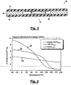
- a section of a typical foil-type pressure sensor 10 is represented in fig. 1 .
- the pressure sensor 10 comprises a first carrier foil 12 and a second carrier foil 14, which are arranged at a certain distance by means of a spacer 16.
- the spacer 16 may e.g. comprise a double-sided bonding sheet.
- the spacer 16 comprises a recess or cut-out 20 such that, in the active area 18, the two carrier foils 12 and 14 face each other at a certain distance.
- Contact arrangements 22 and 24 are arranged in the active area 18 on the inner surfaces of the carrier foils 12 and 14 in such a way that an electrical contact is established between the contact arrangements 22 and 24 if said carrier foils are pressed together.
- one contact arrangement 22 or 24 is arranged on each of said carrier foils 12 and 14 in a facing relationship. It should however be noted that other layouts, e.g. with two spaced contact arrangements 22 and 24 arranged on one of the carrier foils and a shunt element arranged on the second carrier foil, are also possible.
- the contact arrangements may comprise electrodes, wherein at least one of the contact arrangements comprises a layer of pressure sensitive material. Such a layer of pressure sensitive material confers a pressure depending behaviour to the switching element such that the switching element can be used as pressure sensor. It should be noted that the contact arrangements are usually printed onto the respective carrier foils using a screen-printing process prior to the laminating process, in which the carrier foils and the spacer are laminated together.
- the carrier foil of prior art foil-type pressure sensors consists usually of a plastic sheet material such as PET, PI or PEN, which if necessary has undergone a surface treatment in order to enhance the adhesion on the printed electrodes.
- Fig. 2 displays the modulus of elasticity versus temperature for different substrate materials obtained by DMA analyses in the range of -50°C up to +200°C.
- HSPL elasticity of PET
- the corresponding array of response curves R(p,T) covers a well localised R-p-region.
- the turn-on-point ranges between 20 mbar (for +175°C) and 40 mbar (for -50°C).
- the plot of PET/PET system demonstrates the strong increase of the sensitivity of the cell as soon as the temperature exceeds 75°C.
- the turn-on-point of about 70 mbar at RT merges a theoretical value of 5 mbar above 150°C.
- the use of a substrate with a constant elasticity modulus over this temperature range is a needed.
- the film should posses the following properties to fulfil e.g. the automobile and sensor manufacturing requirements:
- multi-layered carrier foils comprising at least two layers of different materials.
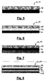
- a multi-layered carrier foil 12, 14 is schematically represented in fig. 5 .
- the shown embodiment comprises two layers 38 and 40 of different materials, e.g. one PET sheet and one PI sheet or one PET sheet and one cured resin layer or metal layer, which are solidly fixed together.
- the two layers 38 and 40 may be fixed by any suitable process.
- the resulting multi-layered carrier foil 12, 14 exhibits mechanical, chemical or electrical properties which are a combination of the individual properties of the two layers 38 and 40.
- the overall thickness of the combined carrier foil does not need to be increased with respect to prior art carrier foils.
- the individual layers 38 and 40 will usually have a thickness, which is only a fraction of the thickness of a classical carrier foil.
- a second embodiment of a carrier foil 12,14 is shown in fig. 6 .
- two layers 38 and 40 of suitable material are laminated together by means of an adhesive layer 42.
- the adhesive layer 42 in the shown embodiment has a thickness comparable to the one of the two layers 38 and 40. It will however be noted, that the thickness of the adhesive layer 42 may as well be much smaller than the thickness of the layers 38 and 40. Alternatively the adhesive layer may be thicker than each of the layers 38 and 40. Furthermore, while the two layers 38 and 40 are shown to have the same thickness, it will be understood, that the different layers may have a different thickness each.
- Each of the three layers 44, 46 and 48 can comprise one of plastic foil, metal or a dielectric resin.
- the three layers are assembled together without the use of an adhesive. Coextrusion or deposition techniques could be used.
- the different layers could have the same thickness or a different thickness each.
- the layers 44 and 48 may be made of the same material or of different materials. It will be noted that the use of a metal layer enables the sensor to be used also as a capacitive sensor. It will further be appreciated that the use of two layers of different metals allow using the bimetal effect in order to deform the carrier foil in the region of the active area into a dome shape.
- dome shaped carrier foil allows to adjust the sensor sensitivity and to increase the homogeneity of the sensor response over a specific temperature range.
- a similar "bimetal" effect may also be obtained with two plastic films, provided that the coefficient of thermal expansion of the two film materials is strongly different.
- An embodiment of the carrier foil with three layers 44, 46 and 48, which are assembled together by lamination is represented in fig. 8 .
- the different layers are laminated together by use of adhesive layers 50 and 52.
- the adhesive layers may comprise the same adhesive of different adhesives, which are adapted to the different materials to be laminated.
- the layers 44 and 48 may be made of the same material or of different materials.
- each of the different layers may have a thickness, which is different from that of the other layers.
- the thickness of the different layers may e.g. be adapted in order to adjust the influence of their dominant property in the combined multi-layered carrier foil properties.
- pressure sensor 22 24 contact arrangements 12 first carrier foil 38, 40 layers 14 second carrier foil 42 adhesive layer 16 spacer 44, 46, 48 different layers 18 active area 50, 52 adhesive layers 20 recess or cut-out
Landscapes
- Push-Button Switches (AREA)
- Contacts (AREA)
- Manufacture Of Switches (AREA)
- Measuring Fluid Pressure (AREA)
- Die Bonding (AREA)
Claims (15)
- Foliendrucksensor (10) umfassend
eine erste Trägerfolie (12) und eine zweite Trägerfolie (14), die mittels eines Abstandshalters (16) in einem bestimmten Abstand voneinander angeordnet sind, wobei der Abstandshalter (16) mindestens eine Aussparung umfasst, die einen aktiven Bereich (18) des Drucksensors (10) definiert, und
mindestens zwei Elektroden (22, 24) und eine Schicht druckempfindlichen Materials, die in dem aktiven Bereich (18) des Drucksensors (10) zwischen der ersten und zweiten Trägerfolie (12, 14) derart angeordnet sind, dass die erste und zweite Trägerfolie (12, 14) als Reaktion auf einen auf den aktiven Bereich (18) des Drucksensors (10) wirkenden Druck gegen die Reaktionskraft der elastischen Trägerfolien zusammengedrückt werden und ein elektrischer Kontakt zwischen den mindestens zwei Elektroden (22, 24) über die Schicht druckempfindlichen Materials hergestellt wird,
dadurch gekennzeichnet, dass mindestens eine der Trägerfolien (12, 14) eine mehrschichtige Konfiguration mit mindestens zwei Schichten (34, 40, 44, 46, 48) verschiedener Materialien mit verschiedenen elastischen Eigenschaften umfasst. - Foliendrucksensor nach Anspruch 1, wobei jede der ersten und zweiten Trägerfolie (12, 14) eine mehrschichtige Konfiguration mit mindestens zwei Schichten (34, 40, 44, 46, 48) verschiedener Materialien umfasst.
- Foliendrucksensor nach Anspruch 2, wobei die Anzahl von Schichten in den mehrschichtigen Konfigurationen der ersten und zweiten Trägerfolie (12, 14) unterschiedlich ist.
- Foliendrucksensor nach Anspruch 2 oder 3, wobei die Schichten der mehrschichtigen Konfiguration der ersten Trägerfolie (12) aus Materialien bestehen, welche von den Materialien der Schichten der mehrschichtigen Konfiguration der zweiten Trägerfolie (14) verschieden sind.
- Foliendrucksensor nach irgendeinem der Ansprüche 1 bis 4, wobei die Schichten (34, 40, 44, 46, 48) der mehrschichtigen Trägerfolie (12, 14) Materialien mit verschiedenen mechanischen Eigenschaften umfassen.
- Foliendrucksensor nach Anspruch 5, wobei die Schichten (34, 40, 44, 46, 48) der mehrschichtigen Trägerfolie Materialien mit einem unterschiedlichen Elastizitätsmodul umfassen.
- Foliendrucksensor nach irgendeinem der Ansprüche 1 bis 6, wobei eine der Schichten (34, 40, 44, 46, 48) der mehrschichtigen Trägerfolie eine dielektrische Harzschicht umfasst.
- Foliendrucksensor nach irgendeinem der Ansprüche 1 bis 7, wobei eine der Schichten (34, 40, 44, 46, 48) der mehrschichtigen Trägerfolie eine Metallfolie umfasst.
- Foliendrucksensor nach irgendeinem der Ansprüche 1 bis 8, wobei die mehrschichtige Trägerfolie zwei Schichten (38, 40) verschiedener Metalle umfasst.
- Foliendrucksensor nach irgendeinem der Ansprüche 1 bis 9, wobei eine der Schichten (34, 40, 44, 46, 48) der mehrschichtigen Trägerfolie ein Material mit einer hohen chemischen Beständigkeit umfasst.
- Foliendrucksensor nach irgendeinem der Ansprüche 1 bis 10, wobei eine der Schichten (34, 40, 44, 46, 48) der mehrschichtigen Trägerfolie ein flammhemmendes Material umfasst.
- Foliendrucksensor nach irgendeinem der Ansprüche 1 bis 11, wobei die verschiedenen Schichten (34, 40, 44, 46, 48) der mehrschichtigen Trägerfolie eine unterschiedliche Dicke aufweisen.
- Foliendrucksensor nach irgendeinem der Ansprüche 1 bis 12, wobei Schichten (34, 40, 44, 46, 48) der mehrschichtigen Trägerfolie aufeinander extrudiert sind.
- Foliendrucksensor nach irgendeinem der Ansprüche 1 bis 13, wobei Schichten (34, 40, 44, 46, 48) der mehrschichtigen Trägerfolie zusammenlaminiert sind.
- Foliendrucksensor nach irgendeinem der Ansprüche 1 bis 14, wobei Schichten (34, 40, 44, 46, 48) der mehrschichtigen Trägerfolie übereinander aufgetragen sind.
Priority Applications (1)
| Application Number | Priority Date | Filing Date | Title |
|---|---|---|---|
| EP03812602A EP1570500B1 (de) | 2002-12-09 | 2003-12-08 | Folientastatur mit mehrschichtiger trägerfolie |
Applications Claiming Priority (4)
| Application Number | Priority Date | Filing Date | Title |
|---|---|---|---|
| EP02102706A EP1429357A1 (de) | 2002-12-09 | 2002-12-09 | Folientastatur mit mehrlagigen Einzelfolien |
| EP02102706 | 2002-12-09 | ||
| EP03812602A EP1570500B1 (de) | 2002-12-09 | 2003-12-08 | Folientastatur mit mehrschichtiger trägerfolie |
| PCT/EP2003/050963 WO2004053908A1 (en) | 2002-12-09 | 2003-12-08 | Foil-type switching element with multi-layered carrier foil |
Publications (2)
| Publication Number | Publication Date |
|---|---|
| EP1570500A1 EP1570500A1 (de) | 2005-09-07 |
| EP1570500B1 true EP1570500B1 (de) | 2011-05-11 |
Family
ID=32319673
Family Applications (2)
| Application Number | Title | Priority Date | Filing Date |
|---|---|---|---|
| EP02102706A Withdrawn EP1429357A1 (de) | 2002-12-09 | 2002-12-09 | Folientastatur mit mehrlagigen Einzelfolien |
| EP03812602A Expired - Lifetime EP1570500B1 (de) | 2002-12-09 | 2003-12-08 | Folientastatur mit mehrschichtiger trägerfolie |
Family Applications Before (1)
| Application Number | Title | Priority Date | Filing Date |
|---|---|---|---|
| EP02102706A Withdrawn EP1429357A1 (de) | 2002-12-09 | 2002-12-09 | Folientastatur mit mehrlagigen Einzelfolien |
Country Status (8)
| Country | Link |
|---|---|
| US (1) | US7543510B2 (de) |
| EP (2) | EP1429357A1 (de) |
| JP (1) | JP2006509337A (de) |
| KR (1) | KR20050085485A (de) |
| CN (1) | CN100442408C (de) |
| AT (1) | ATE509358T1 (de) |
| AU (1) | AU2003300577A1 (de) |
| WO (1) | WO2004053908A1 (de) |
Families Citing this family (21)
| Publication number | Priority date | Publication date | Assignee | Title |
|---|---|---|---|---|
| KR20060126805A (ko) * | 2004-03-02 | 2006-12-08 | 코닌클리케 필립스 일렉트로닉스 엔.브이. | 시간 지연 소프트 스위치 |
| DE102004047516A1 (de) * | 2004-09-28 | 2006-04-06 | Carl Freudenberg Kg | Sensor-Anordnung und Verwendungen einer Sensor-Anordnung |
| DE102004055469A1 (de) * | 2004-11-17 | 2006-05-24 | Siemens Ag | Sensor mit verformungsabhängigem Widerstandswert |
| EP1667183A1 (de) * | 2004-12-01 | 2006-06-07 | IEE INTERNATIONAL ELECTRONICS & ENGINEERING S.A. | Verstärktes folienartiges Schaltelement |
| EP1667182A1 (de) * | 2004-12-01 | 2006-06-07 | IEE INTERNATIONAL ELECTRONICS & ENGINEERING S.A. | Folienartiges Schaltelement mit verbesserter Trägerfolie |
| DE202005000018U1 (de) * | 2005-01-03 | 2005-03-24 | Iee Sarl | Sensormatte mit zwei Schaltniveaus |
| LU91130B1 (en) * | 2005-01-26 | 2006-07-27 | Iee Sarl | Pressure sensitive element and seat sensor |
| EP1731916A1 (de) * | 2005-06-07 | 2006-12-13 | IEE INTERNATIONAL ELECTRONICS & ENGINEERING S.A. | Magnetfeldsensor |
| US20060287140A1 (en) * | 2005-06-16 | 2006-12-21 | Brandt Richard A | Automated line calling system |
| EP2006869A1 (de) | 2007-06-22 | 2008-12-24 | IEE INTERNATIONAL ELECTRONICS & ENGINEERING S.A. | Schaltelement in folienbauweise |
| DE102007043663B4 (de) * | 2007-09-13 | 2011-05-19 | Schurter Gmbh | Aus mehreren elektrischen Tastern bestehende Tastatur |
| CN102023179A (zh) * | 2010-11-04 | 2011-04-20 | 中南大学 | 一种具有电阻自动累积功能的箔式传感器 |
| LU91810B1 (en) * | 2011-04-22 | 2012-10-23 | Iee Sarl | Footwear article with pressure sensor |
| DE102012108444B4 (de) * | 2012-09-11 | 2016-05-12 | Berker Gmbh & Co. Kg | Elektrisches Schaltgerät |
| CN103837272A (zh) * | 2012-11-27 | 2014-06-04 | Ge医疗系统环球技术有限公司 | 一种曲面薄膜压力传感器及其制造方法 |
| JP5604566B1 (ja) * | 2013-07-05 | 2014-10-08 | 株式会社フジクラ | メンブレンスイッチ及び座席装置 |
| JP6698151B2 (ja) * | 2016-03-25 | 2020-05-27 | 株式会社フジクラ | 荷重検知装置 |
| EP3540387B1 (de) * | 2016-11-11 | 2023-02-22 | Fujikura Ltd. | Lastdetektionssensor und lastdetektionssensoreinheit |
| CN108073336A (zh) * | 2016-11-18 | 2018-05-25 | 香港中文大学 | 基于触摸的用户情绪检测系统和方法 |
| WO2019014363A1 (en) * | 2017-07-11 | 2019-01-17 | Joyson Safety Systems Acquisition Llc | OCCUPANT DETECTION SYSTEM, DETECTION MAT AND ELECTRIC SWITCH |
| EP3929540A1 (de) * | 2020-06-26 | 2021-12-29 | TE Connectivity Norge AS | Befestigungssystem zur befestigung eines sensors an einem substrat, verfahren zur befestigung eines sensors an einem substrat |
Citations (4)
| Publication number | Priority date | Publication date | Assignee | Title |
|---|---|---|---|---|
| US3243540A (en) * | 1963-01-17 | 1966-03-29 | Miller Bros | Electric mat switch |
| US4308439A (en) * | 1978-06-08 | 1981-12-29 | Nissan Motor Company, Limited | Switching device |
| EP0491117A1 (de) * | 1990-12-19 | 1992-06-24 | Miller Edge, Inc. | Fühlleiste für eine Tür und Verfahren zur deren Herstellung |
| JPH10149737A (ja) * | 1996-11-19 | 1998-06-02 | Fujikura Ltd | メンブレンスイッチ |
Family Cites Families (34)
| Publication number | Priority date | Publication date | Assignee | Title |
|---|---|---|---|---|
| US3898981A (en) * | 1971-09-01 | 1975-08-12 | Electronic Monitors Inc | Respiration monitoring apparatus |
| WO1981000787A1 (en) | 1979-09-12 | 1981-03-19 | Marshall E Design Int Ltd | Switch structure with touch element |
| US4314227A (en) * | 1979-09-24 | 1982-02-02 | Eventoff Franklin Neal | Electronic pressure sensitive transducer apparatus |
| US4268815A (en) | 1979-11-26 | 1981-05-19 | Eventoff Franklin Neal | Multi-function touch switch apparatus |
| US4517421A (en) | 1980-01-28 | 1985-05-14 | Margolin George D | Resilient deformable keyboard |
| JPS56147540U (de) | 1980-04-04 | 1981-11-06 | ||
| US4520248A (en) | 1980-08-15 | 1985-05-28 | Rogers Corporation | Keyboard assembly |
| US4362911A (en) | 1980-09-17 | 1982-12-07 | Ncr Corporation | Membrane keyboard switch assembly having selectable tactile properties |
| FR2532467A1 (fr) * | 1982-09-01 | 1984-03-02 | Sherman Henry | Clavier a coupelles metalliques |
| US4679030A (en) | 1982-04-30 | 1987-07-07 | Volnak William M | Chording keyboard for generating binary data |
| JPS59101724A (ja) | 1982-11-30 | 1984-06-12 | 日本メクトロン株式会社 | キ−ボ−ドスイツチ |
| DE3513360A1 (de) * | 1985-04-15 | 1986-10-16 | Klaus Dr. 8022 Grünwald Meister | Sicherheits-folientastatur |
| DE3628781A1 (de) | 1985-08-27 | 1987-03-05 | Heiner Flohr | Folientastatur |
| DE3536261A1 (de) * | 1985-10-11 | 1987-04-16 | Basf Ag | Vernetzbare, in waessriger loesung oder dispersion lagerstabile polymere zusammensetzungen, deren herstellung und verwendung |
| US4911053A (en) * | 1986-07-04 | 1990-03-27 | Casio Computer | Electronic stringed instrument having a string trigger switch |
| AU8118587A (en) * | 1986-11-17 | 1988-05-19 | Exicom Australia Pty Limited | Improved membrane keyboard |
| SU1415258A1 (ru) | 1987-01-22 | 1988-08-07 | Предприятие П/Я А-3327 | Коммутационное устройство |
| US4786767A (en) * | 1987-06-01 | 1988-11-22 | Southwall Technologies Inc. | Transparent touch panel switch |
| JPH01176615A (ja) | 1987-12-29 | 1989-07-13 | Matsushita Electric Ind Co Ltd | 両面入力スイッチ |
| US5050034A (en) * | 1990-01-22 | 1991-09-17 | Endress U. Hauser Gmbh U. Co. | Pressure sensor and method of manufacturing same |
| US5060527A (en) * | 1990-02-14 | 1991-10-29 | Burgess Lester E | Tactile sensing transducer |
| US5526703A (en) * | 1992-08-21 | 1996-06-18 | Smiths Industries Aerospace & Defense Systems, Inc. | Force detecting sensor and method of making |
| DE69320977T2 (de) * | 1992-10-05 | 1999-01-28 | Bei Electronics, Inc., Sylmar, Calif. | Ferroelektrischer dünnfilm-wanderwellen-umdrehungssensor |
| US6271482B1 (en) | 1994-08-23 | 2001-08-07 | Thomas & Betts International, Inc. | Conductive elastomer interconnect |
| US5695859A (en) * | 1995-04-27 | 1997-12-09 | Burgess; Lester E. | Pressure activated switching device |
| TW350026B (en) * | 1995-07-28 | 1999-01-11 | Hokushin Ind | Pressure sensor |
| US5871842A (en) | 1996-10-28 | 1999-02-16 | Thomas & Betts International, Inc. | Grafted thermoplastic elastomer barrier layer |
| WO1999007198A1 (en) * | 1997-07-31 | 1999-02-11 | Toyotomi Co., Ltd. | Console panel for equipment |
| US6109113A (en) * | 1998-06-11 | 2000-08-29 | Delco Electronics Corp. | Silicon micromachined capacitive pressure sensor and method of manufacture |
| LU90286B1 (fr) * | 1998-09-11 | 2000-03-13 | Iee Sarl | Capteur de force |
| DE19923806C1 (de) * | 1999-05-19 | 2001-02-08 | Siemens Ag | Folientastatur |
| LU90594B1 (de) * | 2000-06-09 | 2001-12-10 | Iee Sarl | Beleuchtetes Schaltelement |
| GB2367530B (en) * | 2000-10-03 | 2003-07-23 | Nokia Mobile Phones Ltd | User interface device |
| CN2457718Y (zh) * | 2000-12-20 | 2001-10-31 | 信息产业部电子第三十研究所 | 屏蔽式薄膜开关 |
-
2002
- 2002-12-09 EP EP02102706A patent/EP1429357A1/de not_active Withdrawn
-
2003
- 2003-12-08 EP EP03812602A patent/EP1570500B1/de not_active Expired - Lifetime
- 2003-12-08 JP JP2004558116A patent/JP2006509337A/ja active Pending
- 2003-12-08 CN CNB2003801081383A patent/CN100442408C/zh not_active Expired - Fee Related
- 2003-12-08 AT AT03812602T patent/ATE509358T1/de not_active IP Right Cessation
- 2003-12-08 AU AU2003300577A patent/AU2003300577A1/en not_active Abandoned
- 2003-12-08 US US10/538,600 patent/US7543510B2/en not_active Expired - Fee Related
- 2003-12-08 WO PCT/EP2003/050963 patent/WO2004053908A1/en not_active Ceased
- 2003-12-08 KR KR1020057010465A patent/KR20050085485A/ko not_active Withdrawn
Patent Citations (4)
| Publication number | Priority date | Publication date | Assignee | Title |
|---|---|---|---|---|
| US3243540A (en) * | 1963-01-17 | 1966-03-29 | Miller Bros | Electric mat switch |
| US4308439A (en) * | 1978-06-08 | 1981-12-29 | Nissan Motor Company, Limited | Switching device |
| EP0491117A1 (de) * | 1990-12-19 | 1992-06-24 | Miller Edge, Inc. | Fühlleiste für eine Tür und Verfahren zur deren Herstellung |
| JPH10149737A (ja) * | 1996-11-19 | 1998-06-02 | Fujikura Ltd | メンブレンスイッチ |
Also Published As
| Publication number | Publication date |
|---|---|
| US7543510B2 (en) | 2009-06-09 |
| EP1429357A1 (de) | 2004-06-16 |
| ATE509358T1 (de) | 2011-05-15 |
| CN100442408C (zh) | 2008-12-10 |
| JP2006509337A (ja) | 2006-03-16 |
| AU2003300577A1 (en) | 2004-06-30 |
| CN1732543A (zh) | 2006-02-08 |
| EP1570500A1 (de) | 2005-09-07 |
| US20070144882A1 (en) | 2007-06-28 |
| KR20050085485A (ko) | 2005-08-29 |
| WO2004053908A1 (en) | 2004-06-24 |
Similar Documents
| Publication | Publication Date | Title |
|---|---|---|
| US7543510B2 (en) | Foil-type switching element with multi-layered carrier foil | |
| CA1216337A (en) | Pressure sensitive signal generator assembly | |
| EP2006869A1 (de) | Schaltelement in folienbauweise | |
| EP3846277B1 (de) | Batteriesatz | |
| EP1364220A2 (de) | Vorrichtung eines elektronischen druckempfindlichen wandlers und verfahren zu ihrer herstellung | |
| US20060278508A1 (en) | Electroluminescent lamp membrane switch | |
| US20240258594A1 (en) | Battery pack | |
| CN113423598A (zh) | 弯曲的功能膜结构及其制造方法 | |
| WO2011138200A1 (en) | Input device | |
| US20060243579A1 (en) | Foil-type switching element with dielectric layer | |
| EP1718125B9 (de) | Elektrolumineszenz-folie und- element zum beleuchten eines drucktastenschalters | |
| JP2000222981A (ja) | メンブレンスイッチ | |
| EP3540387B1 (de) | Lastdetektionssensor und lastdetektionssensoreinheit | |
| EP1856707B1 (de) | Drucksensor des folientyps mit verbesserter trägerfolie | |
| EP1817782B1 (de) | Verstärktes schaltelement des folientyps | |
| CN113675329B (zh) | 震动模块及其制造方法 | |
| EP4247124A1 (de) | Leiterplatte und verfahren zur herstellung einer leiterplatte | |
| US20080128258A1 (en) | Pressure Sensitive Switching Element and Seat Sensor | |
| KR20190047409A (ko) | 필름인서트 사출성형을 이용한 정전용량방식 터치입력부 포함 기판 제조방법 | |
| JPH06160215A (ja) | 圧力センサおよびその製造方法 | |
| JP2008310968A (ja) | 高分子発熱体 |
Legal Events
| Date | Code | Title | Description |
|---|---|---|---|
| PUAI | Public reference made under article 153(3) epc to a published international application that has entered the european phase |
Free format text: ORIGINAL CODE: 0009012 |
|
| 17P | Request for examination filed |
Effective date: 20050524 |
|
| AK | Designated contracting states |
Kind code of ref document: A1 Designated state(s): AT BE BG CH CY CZ DE DK EE ES FI FR GB GR HU IE IT LI LU MC NL PT RO SE SI SK TR |
|
| AX | Request for extension of the european patent |
Extension state: AL LT LV MK |
|
| DAX | Request for extension of the european patent (deleted) | ||
| 17Q | First examination report despatched |
Effective date: 20060718 |
|
| RIN1 | Information on inventor provided before grant (corrected) |
Inventor name: BIECK, WERNER Inventor name: CHABACH, DRISS Inventor name: SCHLEEH, THOMAS |
|
| GRAP | Despatch of communication of intention to grant a patent |
Free format text: ORIGINAL CODE: EPIDOSNIGR1 |
|
| GRAS | Grant fee paid |
Free format text: ORIGINAL CODE: EPIDOSNIGR3 |
|
| GRAA | (expected) grant |
Free format text: ORIGINAL CODE: 0009210 |
|
| AK | Designated contracting states |
Kind code of ref document: B1 Designated state(s): AT BE BG CH CY CZ DE DK EE ES FI FR GB GR HU IE IT LI LU MC NL PT RO SE SI SK TR |
|
| REG | Reference to a national code |
Ref country code: GB Ref legal event code: FG4D |
|
| REG | Reference to a national code |
Ref country code: CH Ref legal event code: EP |
|
| REG | Reference to a national code |
Ref country code: IE Ref legal event code: FG4D |
|
| REG | Reference to a national code |
Ref country code: DE Ref legal event code: R096 Ref document number: 60337097 Country of ref document: DE Effective date: 20110622 |
|
| REG | Reference to a national code |
Ref country code: NL Ref legal event code: VDEP Effective date: 20110511 |
|
| PG25 | Lapsed in a contracting state [announced via postgrant information from national office to epo] |
Ref country code: PT Free format text: LAPSE BECAUSE OF FAILURE TO SUBMIT A TRANSLATION OF THE DESCRIPTION OR TO PAY THE FEE WITHIN THE PRESCRIBED TIME-LIMIT Effective date: 20110912 Ref country code: SE Free format text: LAPSE BECAUSE OF FAILURE TO SUBMIT A TRANSLATION OF THE DESCRIPTION OR TO PAY THE FEE WITHIN THE PRESCRIBED TIME-LIMIT Effective date: 20110511 |
|
| PG25 | Lapsed in a contracting state [announced via postgrant information from national office to epo] |
Ref country code: BE Free format text: LAPSE BECAUSE OF FAILURE TO SUBMIT A TRANSLATION OF THE DESCRIPTION OR TO PAY THE FEE WITHIN THE PRESCRIBED TIME-LIMIT Effective date: 20110511 Ref country code: GR Free format text: LAPSE BECAUSE OF FAILURE TO SUBMIT A TRANSLATION OF THE DESCRIPTION OR TO PAY THE FEE WITHIN THE PRESCRIBED TIME-LIMIT Effective date: 20110812 Ref country code: SI Free format text: LAPSE BECAUSE OF FAILURE TO SUBMIT A TRANSLATION OF THE DESCRIPTION OR TO PAY THE FEE WITHIN THE PRESCRIBED TIME-LIMIT Effective date: 20110511 Ref country code: ES Free format text: LAPSE BECAUSE OF FAILURE TO SUBMIT A TRANSLATION OF THE DESCRIPTION OR TO PAY THE FEE WITHIN THE PRESCRIBED TIME-LIMIT Effective date: 20110822 Ref country code: CY Free format text: LAPSE BECAUSE OF FAILURE TO SUBMIT A TRANSLATION OF THE DESCRIPTION OR TO PAY THE FEE WITHIN THE PRESCRIBED TIME-LIMIT Effective date: 20110511 Ref country code: FI Free format text: LAPSE BECAUSE OF FAILURE TO SUBMIT A TRANSLATION OF THE DESCRIPTION OR TO PAY THE FEE WITHIN THE PRESCRIBED TIME-LIMIT Effective date: 20110511 Ref country code: AT Free format text: LAPSE BECAUSE OF FAILURE TO SUBMIT A TRANSLATION OF THE DESCRIPTION OR TO PAY THE FEE WITHIN THE PRESCRIBED TIME-LIMIT Effective date: 20110511 |
|
| PG25 | Lapsed in a contracting state [announced via postgrant information from national office to epo] |
Ref country code: NL Free format text: LAPSE BECAUSE OF FAILURE TO SUBMIT A TRANSLATION OF THE DESCRIPTION OR TO PAY THE FEE WITHIN THE PRESCRIBED TIME-LIMIT Effective date: 20110511 |
|
| PG25 | Lapsed in a contracting state [announced via postgrant information from national office to epo] |
Ref country code: EE Free format text: LAPSE BECAUSE OF FAILURE TO SUBMIT A TRANSLATION OF THE DESCRIPTION OR TO PAY THE FEE WITHIN THE PRESCRIBED TIME-LIMIT Effective date: 20110511 Ref country code: CZ Free format text: LAPSE BECAUSE OF FAILURE TO SUBMIT A TRANSLATION OF THE DESCRIPTION OR TO PAY THE FEE WITHIN THE PRESCRIBED TIME-LIMIT Effective date: 20110511 |
|
| PG25 | Lapsed in a contracting state [announced via postgrant information from national office to epo] |
Ref country code: SK Free format text: LAPSE BECAUSE OF FAILURE TO SUBMIT A TRANSLATION OF THE DESCRIPTION OR TO PAY THE FEE WITHIN THE PRESCRIBED TIME-LIMIT Effective date: 20110511 Ref country code: DK Free format text: LAPSE BECAUSE OF FAILURE TO SUBMIT A TRANSLATION OF THE DESCRIPTION OR TO PAY THE FEE WITHIN THE PRESCRIBED TIME-LIMIT Effective date: 20110511 Ref country code: RO Free format text: LAPSE BECAUSE OF FAILURE TO SUBMIT A TRANSLATION OF THE DESCRIPTION OR TO PAY THE FEE WITHIN THE PRESCRIBED TIME-LIMIT Effective date: 20110511 |
|
| PLBE | No opposition filed within time limit |
Free format text: ORIGINAL CODE: 0009261 |
|
| STAA | Information on the status of an ep patent application or granted ep patent |
Free format text: STATUS: NO OPPOSITION FILED WITHIN TIME LIMIT |
|
| 26N | No opposition filed |
Effective date: 20120214 |
|
| PG25 | Lapsed in a contracting state [announced via postgrant information from national office to epo] |
Ref country code: IT Free format text: LAPSE BECAUSE OF FAILURE TO SUBMIT A TRANSLATION OF THE DESCRIPTION OR TO PAY THE FEE WITHIN THE PRESCRIBED TIME-LIMIT Effective date: 20110511 |
|
| REG | Reference to a national code |
Ref country code: DE Ref legal event code: R097 Ref document number: 60337097 Country of ref document: DE Effective date: 20120214 |
|
| PG25 | Lapsed in a contracting state [announced via postgrant information from national office to epo] |
Ref country code: MC Free format text: LAPSE BECAUSE OF NON-PAYMENT OF DUE FEES Effective date: 20111231 |
|
| REG | Reference to a national code |
Ref country code: CH Ref legal event code: PL |
|
| GBPC | Gb: european patent ceased through non-payment of renewal fee |
Effective date: 20111208 |
|
| REG | Reference to a national code |
Ref country code: FR Ref legal event code: ST Effective date: 20120831 |
|
| REG | Reference to a national code |
Ref country code: IE Ref legal event code: MM4A |
|
| PG25 | Lapsed in a contracting state [announced via postgrant information from national office to epo] |
Ref country code: LI Free format text: LAPSE BECAUSE OF NON-PAYMENT OF DUE FEES Effective date: 20111231 Ref country code: CH Free format text: LAPSE BECAUSE OF NON-PAYMENT OF DUE FEES Effective date: 20111231 Ref country code: GB Free format text: LAPSE BECAUSE OF NON-PAYMENT OF DUE FEES Effective date: 20111208 Ref country code: IE Free format text: LAPSE BECAUSE OF NON-PAYMENT OF DUE FEES Effective date: 20111208 |
|
| PG25 | Lapsed in a contracting state [announced via postgrant information from national office to epo] |
Ref country code: FR Free format text: LAPSE BECAUSE OF NON-PAYMENT OF DUE FEES Effective date: 20120102 |
|
| PG25 | Lapsed in a contracting state [announced via postgrant information from national office to epo] |
Ref country code: LU Free format text: LAPSE BECAUSE OF NON-PAYMENT OF DUE FEES Effective date: 20111208 |
|
| PG25 | Lapsed in a contracting state [announced via postgrant information from national office to epo] |
Ref country code: BG Free format text: LAPSE BECAUSE OF FAILURE TO SUBMIT A TRANSLATION OF THE DESCRIPTION OR TO PAY THE FEE WITHIN THE PRESCRIBED TIME-LIMIT Effective date: 20110811 |
|
| PG25 | Lapsed in a contracting state [announced via postgrant information from national office to epo] |
Ref country code: TR Free format text: LAPSE BECAUSE OF FAILURE TO SUBMIT A TRANSLATION OF THE DESCRIPTION OR TO PAY THE FEE WITHIN THE PRESCRIBED TIME-LIMIT Effective date: 20110511 |
|
| PG25 | Lapsed in a contracting state [announced via postgrant information from national office to epo] |
Ref country code: HU Free format text: LAPSE BECAUSE OF FAILURE TO SUBMIT A TRANSLATION OF THE DESCRIPTION OR TO PAY THE FEE WITHIN THE PRESCRIBED TIME-LIMIT Effective date: 20110511 |
|
| PGFP | Annual fee paid to national office [announced via postgrant information from national office to epo] |
Ref country code: DE Payment date: 20161114 Year of fee payment: 14 |
|
| REG | Reference to a national code |
Ref country code: DE Ref legal event code: R119 Ref document number: 60337097 Country of ref document: DE |
|
| PG25 | Lapsed in a contracting state [announced via postgrant information from national office to epo] |
Ref country code: DE Free format text: LAPSE BECAUSE OF NON-PAYMENT OF DUE FEES Effective date: 20180703 |