EP1570338B1 - Règlage simple de paramètres d'images imprimées et de machine pour une imprimante ou un copieur électrophotographique - Google Patents
Règlage simple de paramètres d'images imprimées et de machine pour une imprimante ou un copieur électrophotographique Download PDFInfo
- Publication number
- EP1570338B1 EP1570338B1 EP03758076.8A EP03758076A EP1570338B1 EP 1570338 B1 EP1570338 B1 EP 1570338B1 EP 03758076 A EP03758076 A EP 03758076A EP 1570338 B1 EP1570338 B1 EP 1570338B1
- Authority
- EP
- European Patent Office
- Prior art keywords
- printing
- setting value
- printing unit
- user interface
- operating unit
- Prior art date
- Legal status (The legal status is an assumption and is not a legal conclusion. Google has not performed a legal analysis and makes no representation as to the accuracy of the status listed.)
- Expired - Lifetime
Links
- 239000012876 carrier material Substances 0.000 claims description 13
- 238000000034 method Methods 0.000 claims description 10
- 230000001419 dependent effect Effects 0.000 claims description 3
- 238000010586 diagram Methods 0.000 claims 5
- 239000003550 marker Substances 0.000 claims 4
- 239000000463 material Substances 0.000 claims 2
- 238000005259 measurement Methods 0.000 description 7
- 239000000758 substrate Substances 0.000 description 6
- 238000012986 modification Methods 0.000 description 2
- 230000004048 modification Effects 0.000 description 2
- 230000004913 activation Effects 0.000 description 1
- 238000011161 development Methods 0.000 description 1
- 230000018109 developmental process Effects 0.000 description 1
- 238000006073 displacement reaction Methods 0.000 description 1
- 125000000524 functional group Chemical group 0.000 description 1
- 238000012805 post-processing Methods 0.000 description 1
- 238000007781 pre-processing Methods 0.000 description 1
- 238000003908 quality control method Methods 0.000 description 1
- 230000000007 visual effect Effects 0.000 description 1
Images

Classifications
-
- G—PHYSICS
- G06—COMPUTING; CALCULATING OR COUNTING
- G06F—ELECTRIC DIGITAL DATA PROCESSING
- G06F3/00—Input arrangements for transferring data to be processed into a form capable of being handled by the computer; Output arrangements for transferring data from processing unit to output unit, e.g. interface arrangements
- G06F3/12—Digital output to print unit, e.g. line printer, chain printer
- G06F3/1201—Dedicated interfaces to print systems
- G06F3/1202—Dedicated interfaces to print systems specifically adapted to achieve a particular effect
- G06F3/1203—Improving or facilitating administration, e.g. print management
- G06F3/1205—Improving or facilitating administration, e.g. print management resulting in increased flexibility in print job configuration, e.g. job settings, print requirements, job tickets
-
- G—PHYSICS
- G06—COMPUTING; CALCULATING OR COUNTING
- G06F—ELECTRIC DIGITAL DATA PROCESSING
- G06F3/00—Input arrangements for transferring data to be processed into a form capable of being handled by the computer; Output arrangements for transferring data from processing unit to output unit, e.g. interface arrangements
- G06F3/12—Digital output to print unit, e.g. line printer, chain printer
- G06F3/1201—Dedicated interfaces to print systems
- G06F3/1223—Dedicated interfaces to print systems specifically adapted to use a particular technique
- G06F3/1237—Print job management
- G06F3/1253—Configuration of print job parameters, e.g. using UI at the client
-
- G—PHYSICS
- G06—COMPUTING; CALCULATING OR COUNTING
- G06F—ELECTRIC DIGITAL DATA PROCESSING
- G06F3/00—Input arrangements for transferring data to be processed into a form capable of being handled by the computer; Output arrangements for transferring data from processing unit to output unit, e.g. interface arrangements
- G06F3/12—Digital output to print unit, e.g. line printer, chain printer
- G06F3/1201—Dedicated interfaces to print systems
- G06F3/1278—Dedicated interfaces to print systems specifically adapted to adopt a particular infrastructure
- G06F3/1281—Multi engine printer devices, e.g. one entity having multiple output engines
-
- G—PHYSICS
- G06—COMPUTING; CALCULATING OR COUNTING
- G06F—ELECTRIC DIGITAL DATA PROCESSING
- G06F3/00—Input arrangements for transferring data to be processed into a form capable of being handled by the computer; Output arrangements for transferring data from processing unit to output unit, e.g. interface arrangements
- G06F3/12—Digital output to print unit, e.g. line printer, chain printer
- G06F3/1201—Dedicated interfaces to print systems
- G06F3/1202—Dedicated interfaces to print systems specifically adapted to achieve a particular effect
- G06F3/121—Facilitating exception or error detection and recovery, e.g. fault, media or consumables depleted
Definitions
- the invention relates to an operating unit for at least one electrophotographic printing or copying system.
- the operating unit has a display unit, in which a graphical user interface is displayed.
- the graphical user interface contains a graphical representation of at least one setting value of a first printing unit.
- the invention relates to a graphical user interface and a method for operating at least one electrophotographic printing or copying system.
- printing or copying systems have in a so-called printing or copying individual devices such as printers and various pre- and post-processing units, each a control panel whose user interface is set up in the configuration of each device exactly for this device. Furthermore, printing and copying systems are known in which a common control panel for a feed unit and a printing unit is provided. The control panel was operated using special software that provides a common user interface for the feeder unit and the printing unit.
- printing systems are known in which two separate printers are coupled together so that the paper front side can be printed using the first printer and the paper back using the second printer.
- two-color printing is also referred to as spot color printing.
- printing systems with more than two printers, for example with three or four printers. With these printing systems, the parameters of the respective printer must be set on the operating unit of the respective printer. When changing parameters of the paper to be printed thus changes must be made to all operating units of existing printers in the printing system.
- Two-printer printing systems are also referred to as twin systems and three-printer printing systems as triplex systems.
- the reproduction device can be programmed such that it executes a copy job in accordance with predetermined operating parameters.
- the programming device includes a user interface, each of which displays individual screens from a plurality of display screens on a standard operational level, an order-related level, and a page-level.
- the control panel contains a touch-sensitive LCD display panel This display panel can be used to set different user interfaces for operating the copier.
- a printing system with two operating in tandem printers is known in which control data between an operating unit of the first printer and a control unit of the second printer are transferable. Furthermore, a control unit of the first printer are connected to a control unit of the second printer via a data line. Changed setting values can be transmitted to the other control unit with the aid of the data line.
- a printing and copying system with a display device which outputs a user interface.
- This user interface can be used to make adjustments to the printing or copying system.
- the setting value is output in a simple manner with the aid of the graphical user interface, whereby an operator is informed in a clear manner about the current amount of the setting value. Furthermore, the operator can enter or change the amount of the setting value with the aid of the graphical user interface, whereby an easy handling of the setting values of the printing or copying system is possible.
- a second aspect of the invention relates to a graphical user interface for operating an electrophotographic printing or copying system.
- a graphical representation of at least one setting value of a print image or machine parameter of a printing unit of the printing or copying system takes place.
- the amount of the setting value can be entered using the user interface.
- a third aspect of the invention relates to a method of operating an electrophotographic printing or copying system.
- a graphical user interface By means of a graphical user interface, at least one set value of a print image or machine parameter of a printing unit of the printing or copying system is displayed with the aid of a graphical representation.
- Amount of setting value is inputted by user input via the user interface for changing the current amount of set value.
- a fourth aspect of the invention relates to an operating unit for at least one electrophotographic printing or copying system.
- the operating unit includes a display unit displaying a graphical user interface that includes a graphical representation of the amount of at least one set value of a print image or machine parameter of the printing or copying system.
- the graphical user interface further includes a graphical representation of the amount of the same set value of a second printing unit of the printing or copying system. At least the amount of the setting value of the first printing unit can be entered using the user interface.
- a fifth aspect of the invention relates to a graphical user interface for operating an electrophotographic printing or copying system.
- the graphic user interface graphically represents the magnitude of at least one set value of a print image or machine parameter of a first printing unit of the printing or copying system. Furthermore, with the aid of the graphical user interface, the graphic representation of the same setting value of a second printing unit of the printing or copying system takes place. At least the amount of the setting value of the first printing unit can be entered using the user interface.
- a sixth aspect of the invention relates to a method of operating at least one electrophotographic printing or copying system.
- this procedure is represented by a graphical user interface with the help of a graphical Display at least one set value of a print image or machine parameter of a first printing unit of the printing or copying system displayed.
- a graphic representation of the same setting value of a second printing unit of the printing or copying system is displayed with the aid of the graphical user interface.
- At least the set value of the first printing unit is entered through user input via the user interface.
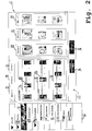
- FIG. 1 a first graphical user interface 10 according to a first embodiment of the invention is shown.
- the graphical user interface 10 contains a first section 12 with display fields and graphical function keys, so-called buttons.
- Section 12 is also referred to as a toolbar or toolbar.
- graphical function keys and display elements are included, which provide information about the current operating state of the printing system. For example, a display element for displaying warnings and alarm messages and a second display element for displaying faults is included.
- a display element for displaying warnings and alarm messages and a second display element for displaying faults is included.
- contact with a service center of the printing system manufacturer can be recorded with the help of the graphic function keys shown there, user settings can be made or provided help instructions can be called up.
- the area 16 also contains a display field in which the name of a currently selected and set user is displayed. In the present embodiment, the user is set to "Developer".
- Section 12 further includes a text output field 18 in which the current operating state in Text form is output. Thus, after the occurrence of a fault condition, a message “not ready” is output in the display panel 18, and in an illustrated configuration mode of the GUI 10, the message "Will be ready” is output.
- the graphical user interface 10 includes a menu 20 in which multiple user interfaces are selectable by means of menu items displayed in a portion 22 of the GUI 10 after selection.
- the menu 20 is essentially structured according to modules and functional units of the printing system.
- the printing system is also referred to as a printing line.
- the menu entry 24 "PNV marks" was selected in the lower menu "CB printer”. This selection displays in section 22 of the graphical user interface 10 a control panel for adjusting the position of print marks, the so-called PNV marks.
- the input and output fields contained on the tabs 26 and 28 are substantially identical.
- the control panel for setting PNV marks is tab 26 of page 1.
- a graphic slider 32 By means of a graphic slider 32, the vertical position of the PNV mark can be adjusted.
- the set value can be in the range from 0 to 12.926 inches.
- the value set with the aid of the slide controller 32 is output as a numerical value.
- the unit of measure of the numerical value currently preset to inches can be changed, eg to the unit mm.
- a numerical value can also be entered directly via a keyboard of an operating unit, on which the graphical user interface 10 is displayed.
- the horizontal position of the PNV mark can be preset.
- the numerical value currently set with the aid of the slide control 34 and in the input and output field 42 the unit of measurement belonging to the numerical value is output.
- a numerical value can also be entered directly in the input and output field 40.
- the tab 26 further includes a graphic slider 44, a graphic slider 46, and a graphic slider 48.
- the graphic slider 48 defines an upper guard area that defines in the vertical direction from the beginning of the page an area where the PNV mark is not generated becomes. With the help of the slider 46, the brand length and with the help of the slider 48, the brand width set.
- the sliders 44, 46 and 48, as well as the slider 32, are each assigned an input and output field for a numerical value and an input and output field for a unit of measure.
- the slider 48 is provided in the same way as the slider 34, an input and output field for a set with the help of the slide control numerical value and an input and output field for the unit of measurement of the numerical value.
- the setting ranges of the sliders 32, 34, 44, 46 and 48 are changed according to the conversion factor to the originally set unit of measure.
- the currently displayed numerical value to which the respective unit of measurement is assigned is also converted and output according to the conversion factor of the changed unit of measure.
- the pointer of the numerical value assigned to the slider 32, 34, 44, 46, 48 is moved accordingly.
- section 50 of section 22 the position of the PNV marks on the front and back is shown graphically.
- the set values can be accepted and the modified setting values can be reset with the aid of the graphic function key 54.
- the view of the PNV marks in the area 50 can be set and changed.
- the toolbar 12 also includes an area 58 containing graphical function keys for operating the printing system. These graphical function keys in area 58 are also provided as buttons on the printing system in terms of hardware. These function keys visually match in form, color and arrangement with the buttons provided on the printing system.
- a pressure channel of the printing system can be selected, wherein a selected and thus activated channel in the area 60 is optically highlighted or marked.
- various print jobs can be aborted by an operator, eg after a fault.
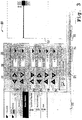
- a graphical user interface 64 according to a second embodiment of the invention is shown.
- the graphical user interface 64 contains a menu 66 in which a user interface can be selected from a plurality of possible user interfaces.
- the menu entries 70 are arranged in a tree-like structure and subdivided into building units and functional groups.
- a selected user interface is displayed in the window 68 of the graphical user interface 64.
- the graphical user interface 64 is provided for operating a printing system with three printers, a so-called triplex unit.
- the first printer prints a print image in a first color on the front of the substrate, the second printer a print image in a second color also on the front of the substrate, the print images are printed one above the other and a so-called spot color print image is generated.
- the third printer prints a printed image in the first color on the back of the substrate.
- preset setting values for each of the three printers can be newly entered and / or changed.
- menu item 70 has been selected and activated, thereby displaying in GUI portion 64 a user interface for adjusting the print quality for printers 1, 2, and 3.
- the tab 72 By selecting the tab 72, it is activated, the slider 74 for adjusting the contrast of a print image, the slider 76 for setting the fixing temperature of a fixing unit, and the slider 78 for adjusting the fixing oil amount to the printer 1 selected via the tab 72.
- the sliding carriage 80 of the slider 74 is in the symbolic representation in the display field 82, the contrast adjustment for printer 1 shown with the aid of a pie chart changed depending on the displacement of the carriage 80 on the slider 74.
- the graphic display of the fixing temperature in the display field 82 by means of a symbolically indicated thermometer also takes place as a function of the value set with the slide 84 of the slide control 76.
- a level in the Meßkapillare depending on the sliding position of the carriage 84 is displayed on the slider 76.
- the setting value of the slide control 78 is also displayed graphically in the display field 82 by means of a symbolic representation.
- a number of five drop-shaped display elements are provided in the display panel 82, which are filled depending on the setting value of the slider 78, a part or all of the display elements with the frame color of the display elements or filled with the background color of the display elements. This graphically illustrates the amount of fixing oil used to fix a toner image deposited on the substrate.
- a display panel 86 and a display panel 88 are provided, the display panel 86 relating to the print quality settings for the printer 2 and the display panel 88 to the print quality settings of the printer 3.
- the display field 82 is rich in contrast and the display fields 86 and 88 display low contrast.
- the display panel 82 may be displayed in a color representation and the display panels 86 and 88 may be displayed in a greyscale display. This makes it clear that with the help of the sliders 74, 76 and 78 settings affect the printer 1.
- Tab 90 and tab 92 are provided adjacent tab 72, tab 90 being printer 2 and tab 92 being printer 3.
- the tab label of the selected printer is displayed in black color and the tab labels of the non-selected printers are displayed in a gray color.
- the name of the printer selected using the tabs 72, 90, 92 becomes clear.
- the tabs 72, 90, 92 each contain the same sliders 74, 76, 78 for contrast, fixing temperature and fixing oil.
- the display field 82, 86, 88 or the display field 82, 86, 88 associated with the tab 72, 90, 92 is assigned to the same printer , such as the tabs 72, 90, 92, are displayed in a color representation, with the remaining two display panels 82, 86, 88 displayed in a greyscale representation.
- the printer 2 and the printer 3 are coupled to each other such that when the fixing temperature of the printer 3 is raised, the fixing temperatures of the printers 1 and 2 are automatically reduced. This ensures that the carrier material is relatively lightly stressed during the fixation in the first and second printer and the high relative fixing temperature in the printer 3, a high-quality and permanent fixation of the toner images on the substrate.
- the currently changed setting values can be accepted and with the help of the function key 96 the currently changed setting values can be discarded and the user interface for setting the print quality can be left.
- the graphical user interface 64 after FIG. 2 has been optimized for operation with the aid of a touch-sensitive screen and is suitable for so-called finger operation.
- the adjustment of the sliding carriages 80 and 84 of the sliders 74, 76, 78 can be changed stepwise by touching the shaded areas.
- the sliding carriage 80, 84 is also referred to as a scale pointer.
- the selection of the respective tab 72, 90, 92 takes place by touching the respective tab.
- the selection of the menu items and the opening of the submenus is also done by a finger touch of the respective menu or menu item.
- repeatedly used setting values are stored by the operating unit.
- the stored setting values are used as scale values and as adjusting positions for dividing a scale of the respective graphic slider 74, 76, 78 or a pie chart for inputting the setting values.
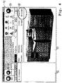
- FIG. 3 is a graphical user interface 100 similar to the user interface 64 after FIG. 2 shown.
- the graphical user interface 100 includes a menu 102.
- the menu item Control Marks has been activated, whereby in the section 104 of the graphical user interface 100 a user interface for setting a control mark position is displayed.
- a tax stamp is generated by means of the printer 1 and detected by the printer 2 and printer 3, which then respectively determine the position of a print image to be generated depending on the position of these tax stamps.
- the printer 1, which is arranged in the transport direction of the carrier material in front of the printer 2 and the printer 3 and thus produces the first of these three printers a printed image on the supplied carrier material, generates in addition to the actual printed image such a tax stamp.
- the fact that the tax stamp is only generated by the printer 1, the tab 106 for printer 1 is automatically activated when selecting the menu item Tax stamps.
- Tabs 108 and 110 which appear on other user interfaces, such as the print quality control interface FIG. 2 that affect printers 2 and 3 can not be activated on the user interface to set the control mark position.
- a so-called check box is activated.
- graphical function keys 114 and 116 the horizontal position and, with the aid of the function keys 118, 120, the vertical position is changed in pre-set steps upon activation of these function keys 114, 116.
- the limit values of the position are contained on the function keys 114, 116.
- the current setting value is displayed in input and output fields 122 and 124, respectively.
- an input and output field 126 the unit of measure assigned to the numerical value output in the input and output field 122 is displayed, wherein this unit of measurement can be changed with the aid of a so-called selection menu.
- the numerical value currently displayed in the input and output field 122 is then converted and displayed as a function of the conversion factor of the original unit of measure to the changed unit of measure.
- a unit of measurement for the numerical value output in the input and output field 124 is indicated in the input and output field 128.
- the limit values displayed on the function keys are also converted and displayed when changing the unit of measure, depending on the conversion factor.
- Further function keys 130 to 144 define an upper protection range, the width of the tax code, the length of the tax code and a lower protection range.
- the currently set numerical values are displayed in assigned input and output fields, each of which has an input and output field is assigned for displaying and changing the unit of measure.
- the graphical user interface 100 further includes a graphical function key 146 for accepting the changed set values, whereby the set values are then used to control the printing system. With the aid of another function key 148, the changed setting values can be discarded and the user interface for setting the control marks is left. Further, the graphical user interface 100 includes a display area 150 in which the position of the control mark on the substrate is graphically displayed, and when the setting values are changed, the position of the setting mark or the size of the setting mark is shifted depending on the changes made.
- a graphical user interface 152 according to a fourth embodiment of the invention is shown.
- This graphical user interface includes a first section 154 with a so-called toolbar containing graphical function buttons, so-called buttons, for controlling the printing system.
- the graphical user interface 152 includes a menu 156 in which a user interface displayed in a portion 158 of the graphical user interface 152 is selectable.
- the graphical user interface 152 contains a section 160 in which the input and output of important printing parameters takes place. For example, the name of the printer and the name of the current print job are displayed.
- the text output field 160 contains information about a setup program module and supported printer languages.
Landscapes
- Engineering & Computer Science (AREA)
- Theoretical Computer Science (AREA)
- Human Computer Interaction (AREA)
- Physics & Mathematics (AREA)
- General Engineering & Computer Science (AREA)
- General Physics & Mathematics (AREA)
- User Interface Of Digital Computer (AREA)
- Accessory Devices And Overall Control Thereof (AREA)
- Control Or Security For Electrophotography (AREA)
- Exposure Or Original Feeding In Electrophotography (AREA)
Claims (22)
- Unité de commande pour au moins un système électrophotographique d'impression ou de copie, comprenant une unité d'affichage sur laquelle est affichée une surface graphique d'utilisateur (10, 64, 100, 152) qui contient une représentation graphique (74, 76, 78, 82) du niveau d'au moins une valeur de réglage d'un paramètre d'une image ou d'une machine d'impression d'une unité d'impression du système d'impression ou de copie,
la surface graphique d'utilisateur (10, 64, 100, 152) contenant une représentation graphique (86, 88) du niveau de la même valeur de réglage d'une deuxième unité d'impression du système d'impression ou de copie, au moins le niveau de la valeur de réglage (74, 79, 78) de la première unité d'impression pouvant être introduit à l'aide de la surface d'utilisateur (10, 64, 100, 152),
des valeurs de réglage utilisées à répétition pouvant être conservées en mémoire dans l'unité de commande et ces valeurs de réglage utilisées à répétition et conservées en mémoire servant de valeurs d'échelle qui divisent une échelle d'un régulateur graphique coulissant (74, 76, 78) ou d'un diagramme circulaire,
chaque unité d'impression possédant une unité de commande séparée, la valeur de réglage de la première unité d'impression et la valeur de réglage de la deuxième unité d'impression pouvant toutes deux êtres affichées et introduites sur l'unité de commande de la première unité d'impression et sur l'unité de commande de la deuxième unité d'impression. - Unité de commande selon la revendication 1, caractérisée en ce que la valeur de réglage (74, 76, 78) concerne le contraste, la luminosité, le niveau d'huile de fixation, des paramètres du papier et/ou la position d'un repère d'impression des unités d'impression.
- Unité de commande selon les revendications 1 ou 2, caractérisée en ce que la représentation graphique des valeurs de réglage peut être introduite et/ou présentée à l'aide de la présentation de chiffres (122, 124), à l'aide d'un régulateur graphique coulissant (74, 76, 78) et/ou à l'aide d'un diagramme circulaire.
- Unité de commande selon la revendication 3, caractérisée en ce que la valeur de réglage en cours du régulateur coulissant (74, 76, 78) est affichée à l'aide d'un pointeur d'échelle (80, 84) sur une échelle du régulateur coulissant (74, 76, 78), le pointeur d'échelle (80, 84) pouvant être déplacé à l'aide d'un appareil d'introduction, de telle sorte que lors de la présentation de la valeur de réglage à l'aide de chiffres, le niveau de la valeur de réglage puisse être augmenté ou diminué pas à pas par des touches (114, 116) de fonctions graphiques et en ce que le niveau de la valeur de réglage présenté à l'aide du diagramme circulaire peut être modifié par déplacement de la position d'un repère de réglage et disposé sur le diagramme circulaire et/ou par introduction par l'intermédiaire de touches (114, 116) de fonctions graphiques.
- Unité de commande selon l'une des revendications précédentes, caractérisée en ce que la valeur de réglage de la deuxième unité d'impression peut être introduite à l'aide de la surface d'utilisateur (64).
- Unité de commande selon l'une des revendications précédentes, caractérisée en ce qu'une unité centrale de commande est prévue pour la première unité d'impression et la deuxième unité d'impression.
- Unité de commande selon l'une des revendications précédentes, caractérisée en ce que la valeur de réglage est représentée sous la forme d'une barre ou d'un symbole graphique, la valeur de réglage pouvant être modifiée par l'intermédiaire de l'introduction de chiffres, par l'intermédiaire de données de fonctions graphiques, le graphique en barres ou en symboles étant modifié en fonction de la valeur introduite.
- Unité de commande selon l'une des revendications précédentes, caractérisée en ce que le niveau de la valeur de réglage de la première unité d'impression peut être modifié indépendamment du niveau de la deuxième unité d'impression.
- Unité de commande selon la revendication 8, caractérisée en ce que la valeur de réglage concerne le contraste, la luminosité, le niveau d'huile de fixation, des paramètres du papier et/ou la position d'un repère d'impression des unités d'impression, et en ce que la position de l'image imprimée que doit former l'unité d'impression est définie en fonction de la position des repères de position sur le matériau du support.
- Unité de commande selon l'une des revendications précédentes, caractérisée en ce que lors d'une modification du niveau de la valeur de réglage de la première unité d'impression, le niveau de la valeur de réglage de la deuxième unité d'impression est modifié de la même manière et en ce que lors d'une modification du niveau de la valeur de réglage de la deuxième unité d'impression, le niveau de la valeur de réglage de la première unité d'impression est modifié de manière correspondante.
- Unité de commande selon la revendication 8, caractérisée en ce que la valeur de réglage concerne au moins un paramètre du matériau de support.
- Unité de commande selon l'une des revendications précédentes, caractérisée en ce que la première unité d'impression et la deuxième unité d'impression sont des composants séparés.
- Unité de commande selon l'une des revendications précédentes, caractérisée en ce que la première unité d'impression et la deuxième unité d'impression sont accouplées l'une à l'autre de telle sorte que la première unité d'impression forme une image imprimée sur la face avant du matériau de support et que la deuxième unité d'impression forme une image imprimée sur la face arrière du matériau de support ou la première unité d'impression forme une première image imprimée sur la face avant du matériau de support et la deuxième unité d'impression forme une image imprimée sur la face avant du matériau de support.
- Unité de commande selon la revendication 13, caractérisée en ce que le type et/ou la couleur du matériau d'encrage avec lequel la première unité d'impression forme une image imprimée sont différents du type et/ou de la couleur du matériau d'encrage avec lequel la deuxième unité d'impression forme une image imprimée.
- Unité de commande selon l'une des revendications 13 ou 14, caractérisée en ce que le matériau de support est un matériau de support sans fin.
- Unité de commande selon l'une des revendications précédentes, caractérisée en ce que la surface graphique d'utilisateur (10, 64, 100, 152) contient en outre la représentation graphique de la même valeur de réglage d'une troisième unité d'impression.
- Unité de commande selon l'une des revendications précédentes, caractérisée en ce que la surface graphique de commande contient un élément d'affichage (154, 166) qui signale la présence de données d'impression qui doivent encore être traitées.
- Unité de commande selon l'une des revendications précédentes, caractérisée en ce qu'elle présente un élément d'affichage (60) qui indique au moins un canal d'impression actif de l'imprimante.
- Unité de commande selon les revendications 17 ou 18, caractérisée en ce que l'élément d'affichage est un champ d'affichage coloré et/ou la présentation d'un texte.
- Unité de commande selon la revendication 19, caractérisée en ce que le champ d'affichage contient un symbole graphique.
- Unité de commande selon les revendications 19 ou 20, caractérisée en ce que le champ d'affichage est disposé dans une réglette d'outil (12, 154) de la surface graphique d'utilisateur (10, 64, 100, 152), le champ d'affichage étant coloré dans une première couleur peu contrastée dans un premier état de fonctionnement et coloré en une couleur essentiellement très contrastée par rapport à l'environnement du champ d'affichage dans un deuxième état de fonctionnement.
- Procédé de commande d'au moins un système électrophotographique d'impression ou de copie selon la revendication 1, dans lequel au moins une valeur de réglage d'un paramètre de l'image imprimée ou de la machine d'impression d'une unité d'impression du système d'impression ou de copie est affichée par une surface graphique d'utilisateur (10, 64, 100, 152) présentant une représentation graphique (74, 64, 100, 152), au moins la valeur de réglage (74, 78, 82, 122) étant introduite par une introduction de l'utilisateur par l'intermédiaire de la surface d'utilisateur (10, 64, 100, 152), des valeurs de réglage utilisées à répétition étant conservées en mémoire dans l'unité de commande, ces valeurs de réglage utilisées à répétition servant de valeurs d'échelle pour diviser une échelle d'un régulateur graphique coulissant (74, 76, 78) ou d'un diagramme circulaire,
l'affichage de la présentation graphique (74, 76, 78, 82, 122) par la surface graphique d'utilisateur (10, 64, 100, 152) de la ou des valeurs de réglage du paramètre de l'image imprimée ou de la machine d'impression concernant une première unité d'impression du système d'impression ou de copie,
une représentation graphique (74, 76, 78, 82, 122) de la même valeur de réglage d'une deuxième unité d'impression du système d'impression ou de copie étant affichée à l'aide de la surface graphique d'utilisateur (10, 64, 100, 152) et
au moins la valeur de réglage (74, 76, 78, 80, 122) de la première unité d'impression est introduite par l'introduction par l'utilisateur par l'intermédiaire de la surface d'utilisateur (10, 64, 100, 152).
Applications Claiming Priority (3)
| Application Number | Priority Date | Filing Date | Title |
|---|---|---|---|
| DE10250182 | 2002-10-28 | ||
| DE10250182A DE10250182A1 (de) | 2002-10-28 | 2002-10-28 | Einfaches Einstellen von Druckerparameter mit Hilfe einer Bedieneinheit für mindestens zwei elektrofotografische Drucker oder Kopierer |
| PCT/EP2003/011960 WO2004038579A2 (fr) | 2002-10-28 | 2003-10-28 | Reglage simple de parametres d'images imprimees et de machine pour une imprimante ou un copieur electrophotographique |
Publications (2)
| Publication Number | Publication Date |
|---|---|
| EP1570338A2 EP1570338A2 (fr) | 2005-09-07 |
| EP1570338B1 true EP1570338B1 (fr) | 2017-07-19 |
Family
ID=32103115
Family Applications (1)
| Application Number | Title | Priority Date | Filing Date |
|---|---|---|---|
| EP03758076.8A Expired - Lifetime EP1570338B1 (fr) | 2002-10-28 | 2003-10-28 | Règlage simple de paramètres d'images imprimées et de machine pour une imprimante ou un copieur électrophotographique |
Country Status (4)
| Country | Link |
|---|---|
| US (1) | US7187884B2 (fr) |
| EP (1) | EP1570338B1 (fr) |
| DE (1) | DE10250182A1 (fr) |
| WO (1) | WO2004038579A2 (fr) |
Families Citing this family (25)
| Publication number | Priority date | Publication date | Assignee | Title |
|---|---|---|---|---|
| US7376469B2 (en) * | 2005-04-15 | 2008-05-20 | International Business Machines Corporation | Methods and apparatus for implementing manual and hybrid control modes in automated graphical indicators and controls |
| US8223385B2 (en) * | 2006-12-07 | 2012-07-17 | Xerox Corporation | Printer job visualization |
| US8165450B2 (en) | 2007-11-19 | 2012-04-24 | Echostar Technologies L.L.C. | Methods and apparatus for filtering content in a video stream using text data |
| US8165451B2 (en) | 2007-11-20 | 2012-04-24 | Echostar Technologies L.L.C. | Methods and apparatus for displaying information regarding interstitials of a video stream |
| KR101266383B1 (ko) * | 2008-01-07 | 2013-05-22 | 삼성전자주식회사 | 작업 대상 원고의 위조 방지 방법 및 작업 대상 원고의위조 방지 기능을 가지는 양면인쇄가 가능한 복합기 |
| US8606085B2 (en) | 2008-03-20 | 2013-12-10 | Dish Network L.L.C. | Method and apparatus for replacement of audio data in recorded audio/video stream |
| US8156520B2 (en) | 2008-05-30 | 2012-04-10 | EchoStar Technologies, L.L.C. | Methods and apparatus for presenting substitute content in an audio/video stream using text data |
| US20090303188A1 (en) * | 2008-06-05 | 2009-12-10 | Honeywell International Inc. | System and method for adjusting a value using a touchscreen slider |
| US8407735B2 (en) | 2008-12-24 | 2013-03-26 | Echostar Technologies L.L.C. | Methods and apparatus for identifying segments of content in a presentation stream using signature data |
| US8510771B2 (en) | 2008-12-24 | 2013-08-13 | Echostar Technologies L.L.C. | Methods and apparatus for filtering content from a presentation stream using signature data |
| US8588579B2 (en) | 2008-12-24 | 2013-11-19 | Echostar Technologies L.L.C. | Methods and apparatus for filtering and inserting content into a presentation stream using signature data |
| US8437617B2 (en) | 2009-06-17 | 2013-05-07 | Echostar Technologies L.L.C. | Method and apparatus for modifying the presentation of content |
| US8934758B2 (en) * | 2010-02-09 | 2015-01-13 | Echostar Global B.V. | Methods and apparatus for presenting supplemental content in association with recorded content |
| DE102010051028A1 (de) * | 2010-11-11 | 2012-06-06 | Heidelberger Druckmaschinen Ag | Maschinenbedienung mit Browser |
| JP5963420B2 (ja) * | 2011-11-14 | 2016-08-03 | キヤノン株式会社 | 画像処理システム、画像処理装置及びその制御方法、並びにプログラム |
| JP2015011206A (ja) * | 2013-06-28 | 2015-01-19 | 株式会社沖データ | 画像形成装置及び制御プログラム |
| USD760271S1 (en) * | 2014-03-19 | 2016-06-28 | Wargaming.Net Limited | Display screen with graphical user interface |
| KR20160047313A (ko) * | 2014-10-22 | 2016-05-02 | 삼성전자주식회사 | 디바이스 제어 방법 및 그 디바이스 |
| JP6439439B2 (ja) * | 2014-12-24 | 2018-12-19 | 株式会社リコー | 情報処理装置、画像処理装置、プログラム、ユーザインタフェース |
| JP6565219B2 (ja) * | 2015-03-03 | 2019-08-28 | 株式会社ジェイテクト | 操作盤 |
| DE102015119681A1 (de) * | 2015-11-13 | 2017-05-18 | Phoenix Contact Gmbh & Co. Kg | Verfahren zur Eingabe von Druckdaten für die Bedruckung eines Bedruckungsobjekts mit einem Drucker und Drucksystem mit mindestens zwei Druckern |
| JP1580172S (fr) * | 2016-06-29 | 2017-07-03 | ||
| USD812072S1 (en) * | 2017-03-29 | 2018-03-06 | Sorenson Ip Holdings, Llc | Display screen or a portion thereof with graphical user interface |
| WO2021054934A1 (fr) | 2019-09-16 | 2021-03-25 | Hewlett-Packard Development Company, L.P. | Interface de prise de main |
| US11172269B2 (en) | 2020-03-04 | 2021-11-09 | Dish Network L.L.C. | Automated commercial content shifting in a video streaming system |
Citations (1)
| Publication number | Priority date | Publication date | Assignee | Title |
|---|---|---|---|---|
| WO2001071478A2 (fr) * | 2000-03-22 | 2001-09-27 | Sony Electronics Inc | Interface utilisateur de saisie de donnees |
Family Cites Families (10)
| Publication number | Priority date | Publication date | Assignee | Title |
|---|---|---|---|---|
| GB2130837B (en) * | 1982-10-01 | 1987-04-23 | Canon Kk | Facsimile processing control |
| US5105220A (en) * | 1990-08-06 | 1992-04-14 | Xerox Corporation | Operator introduction screen |
| US5390005A (en) * | 1992-07-13 | 1995-02-14 | Konica Corporation | Operation-panel-indicating method for a copying machine |
| JP3215174B2 (ja) * | 1992-09-01 | 2001-10-02 | キヤノン株式会社 | 画像処理装置およびその制御方法、並びに、情報処理装置およびその方法 |
| US5467170A (en) * | 1993-12-22 | 1995-11-14 | Eastman Kodak Company | Reproduction apparatus with multiple means for creating incrementing alpha-numeric page stamps |
| US5585891A (en) * | 1995-03-29 | 1996-12-17 | Eastman Kodak Company | Set-up navigation scheme for programming reproduction apparatus |
| US6097887A (en) * | 1997-10-27 | 2000-08-01 | Kla-Tencor Corporation | Software system and method for graphically building customized recipe flowcharts |
| DE19836745C2 (de) * | 1998-08-13 | 2003-07-24 | Oce Printing Systems Gmbh | Tandem-Drucksystem |
| JP3569159B2 (ja) * | 1999-06-22 | 2004-09-22 | シャープ株式会社 | 画像生成装置 |
| US6744527B1 (en) | 1999-06-29 | 2004-06-01 | Xerox Corporation | User interface for navigation and control of a printing system |
-
2002
- 2002-10-28 DE DE10250182A patent/DE10250182A1/de not_active Withdrawn
-
2003
- 2003-10-28 WO PCT/EP2003/011960 patent/WO2004038579A2/fr not_active Application Discontinuation
- 2003-10-28 EP EP03758076.8A patent/EP1570338B1/fr not_active Expired - Lifetime
- 2003-10-28 US US10/531,824 patent/US7187884B2/en not_active Expired - Lifetime
Patent Citations (1)
| Publication number | Priority date | Publication date | Assignee | Title |
|---|---|---|---|---|
| WO2001071478A2 (fr) * | 2000-03-22 | 2001-09-27 | Sony Electronics Inc | Interface utilisateur de saisie de donnees |
Also Published As
| Publication number | Publication date |
|---|---|
| EP1570338A2 (fr) | 2005-09-07 |
| DE10250182A1 (de) | 2004-05-13 |
| US20060133839A1 (en) | 2006-06-22 |
| WO2004038579A3 (fr) | 2004-07-22 |
| WO2004038579A2 (fr) | 2004-05-06 |
| US7187884B2 (en) | 2007-03-06 |
Similar Documents
| Publication | Publication Date | Title |
|---|---|---|
| EP1570338B1 (fr) | Règlage simple de paramètres d'images imprimées et de machine pour une imprimante ou un copieur électrophotographique | |
| EP1620265B1 (fr) | Systeme pour inspecter une impression | |
| DE10051680B4 (de) | Schema zur Darstellung mehrerer Druckauftragsabänderungselemente in einer Drucksoftware-Benutzerschnittstelle | |
| EP0979172A1 (fr) | Procede d'exploitation d'une imprimante ou d'une photocopieuse a grande vitesse avec instructions sur la procedure a suivre en cas d'incidents | |
| EP1388042B1 (fr) | Procede, systeme d'appareillage et systeme de programmes informatiques permettant de controler visuellement un flux de donnees d'impression | |
| EP1563344B1 (fr) | Interface utilisateur graphique et procede pour indiquer un dysfonctionnement d'un systeme d'impression ou de copie electro-photographique | |
| WO2010149453A1 (fr) | Dispositifs pour commander un dispositif de dosage d'un mécanisme d'encrage et/ou d'un mécanisme de mouillage d'une rotative à bobines et rotative à bobines et procédé pour la commande de la rotative à bobines | |
| DE69908462T2 (de) | Benutzer-Schnittstelle für Informationsverarbeitungssystem | |
| EP2090434B1 (fr) | Procédé destiné au fonctionnement d'une presse | |
| DE4413230A1 (de) | Bedienpult für eine Druckmaschine | |
| DE69330125T2 (de) | Verfahren und Vorrichtung zur automatischen Änderung der Betriebsbedingungen von Machinen oder Apparaten | |
| DE3719817C2 (fr) | ||
| DE10317064A1 (de) | Vorrichtungen und Verfahren zur Steuerung einer Anlage | |
| DE3046037A1 (de) | Textbearbeitungsgeraet | |
| DE102017205469A1 (de) | Verfahren zur Bestimmung der Reihenfolge bei der Abarbeitung von Druckaufträgen und eine Druckmaschine mit Steuerungsrechner | |
| DE102017205470A1 (de) | Verfahren zur Bestimmung der Reihenfolge bei der Abarbeitung von Druckaufträgen und eine Druckmaschine mit Steuerungsrechner | |
| DE69411869T2 (de) | Bildwiedergabegerät mit Eingabe alpha-numerischer Zeichen | |
| EP2045711A2 (fr) | Système de contrôle pour produits d'impression | |
| EP1433606B1 (fr) | Procédé et dispositif pour commander une machine à imprimer | |
| DE69413498T2 (de) | Druckbildstellungsanzeigevorrichtung | |
| EP0990519B1 (fr) | Module de commande pour le dispositif de commande d'une machine à imprimer | |
| EP3769966B1 (fr) | Guidage automatique de menu d'utilisation assisté au niveau de couleurs | |
| DE102017205471A1 (de) | Verfahren zur Bestimmung der Reihenfolge bei der Abarbeitung von Druckaufträgen und eine Druckmaschine mit Steuerungsrechner | |
| DE10262033B4 (de) | Verfahren und Anordnung zum einfachen Bedienen, Warten und/oder Konfigurieren eines elektrofotografischen Druck- oder Kopiersystems | |
| DE69525384T2 (de) | Drucker mit Mitteln zur Wahl der Betriebsart |
Legal Events
| Date | Code | Title | Description |
|---|---|---|---|
| PUAI | Public reference made under article 153(3) epc to a published international application that has entered the european phase |
Free format text: ORIGINAL CODE: 0009012 |
|
| 17P | Request for examination filed |
Effective date: 20050527 |
|
| AK | Designated contracting states |
Kind code of ref document: A2 Designated state(s): AT BE BG CH CY CZ DE DK EE ES FI FR GB GR HU IE IT LI LU MC NL PT RO SE SI SK TR |
|
| AX | Request for extension of the european patent |
Extension state: AL LT LV MK |
|
| DAX | Request for extension of the european patent (deleted) | ||
| RBV | Designated contracting states (corrected) |
Designated state(s): DE FR GB |
|
| 17Q | First examination report despatched |
Effective date: 20111017 |
|
| RAP1 | Party data changed (applicant data changed or rights of an application transferred) |
Owner name: OCE PRINTING SYSTEMS GMBH & CO. KG |
|
| GRAP | Despatch of communication of intention to grant a patent |
Free format text: ORIGINAL CODE: EPIDOSNIGR1 |
|
| STAA | Information on the status of an ep patent application or granted ep patent |
Free format text: STATUS: GRANT OF PATENT IS INTENDED |
|
| INTG | Intention to grant announced |
Effective date: 20170220 |
|
| GRAS | Grant fee paid |
Free format text: ORIGINAL CODE: EPIDOSNIGR3 |
|
| GRAA | (expected) grant |
Free format text: ORIGINAL CODE: 0009210 |
|
| STAA | Information on the status of an ep patent application or granted ep patent |
Free format text: STATUS: THE PATENT HAS BEEN GRANTED |
|
| AK | Designated contracting states |
Kind code of ref document: B1 Designated state(s): DE FR GB |
|
| REG | Reference to a national code |
Ref country code: GB Ref legal event code: FG4D Free format text: NOT ENGLISH |
|
| REG | Reference to a national code |
Ref country code: DE Ref legal event code: R096 Ref document number: 50315678 Country of ref document: DE |
|
| REG | Reference to a national code |
Ref country code: DE Ref legal event code: R097 Ref document number: 50315678 Country of ref document: DE |
|
| PLBE | No opposition filed within time limit |
Free format text: ORIGINAL CODE: 0009261 |
|
| STAA | Information on the status of an ep patent application or granted ep patent |
Free format text: STATUS: NO OPPOSITION FILED WITHIN TIME LIMIT |
|
| 26N | No opposition filed |
Effective date: 20180420 |
|
| GBPC | Gb: european patent ceased through non-payment of renewal fee |
Effective date: 20171028 |
|
| REG | Reference to a national code |
Ref country code: FR Ref legal event code: ST Effective date: 20180629 |
|
| PG25 | Lapsed in a contracting state [announced via postgrant information from national office to epo] |
Ref country code: GB Free format text: LAPSE BECAUSE OF NON-PAYMENT OF DUE FEES Effective date: 20171028 |
|
| PG25 | Lapsed in a contracting state [announced via postgrant information from national office to epo] |
Ref country code: FR Free format text: LAPSE BECAUSE OF NON-PAYMENT OF DUE FEES Effective date: 20171031 |
|
| PGFP | Annual fee paid to national office [announced via postgrant information from national office to epo] |
Ref country code: DE Payment date: 20201022 Year of fee payment: 18 |
|
| REG | Reference to a national code |
Ref country code: DE Ref legal event code: R119 Ref document number: 50315678 Country of ref document: DE |
|
| PG25 | Lapsed in a contracting state [announced via postgrant information from national office to epo] |
Ref country code: DE Free format text: LAPSE BECAUSE OF NON-PAYMENT OF DUE FEES Effective date: 20220503 |