EP1569756B1 - Brause mit luftzuführung - Google Patents
Brause mit luftzuführung Download PDFInfo
- Publication number
- EP1569756B1 EP1569756B1 EP03789235A EP03789235A EP1569756B1 EP 1569756 B1 EP1569756 B1 EP 1569756B1 EP 03789235 A EP03789235 A EP 03789235A EP 03789235 A EP03789235 A EP 03789235A EP 1569756 B1 EP1569756 B1 EP 1569756B1
- Authority
- EP
- European Patent Office
- Prior art keywords
- water
- shower outlet
- shower
- outlet according
- jet
- Prior art date
- Legal status (The legal status is an assumption and is not a legal conclusion. Google has not performed a legal analysis and makes no representation as to the accuracy of the status listed.)
- Expired - Lifetime
Links
Images


Classifications
-
- B—PERFORMING OPERATIONS; TRANSPORTING
- B05—SPRAYING OR ATOMISING IN GENERAL; APPLYING FLUENT MATERIALS TO SURFACES, IN GENERAL
- B05B—SPRAYING APPARATUS; ATOMISING APPARATUS; NOZZLES
- B05B7/00—Spraying apparatus for discharge of liquids or other fluent materials from two or more sources, e.g. of liquid and air, of powder and gas
- B05B7/02—Spray pistols; Apparatus for discharge
- B05B7/04—Spray pistols; Apparatus for discharge with arrangements for mixing liquids or other fluent materials before discharge
- B05B7/0416—Spray pistols; Apparatus for discharge with arrangements for mixing liquids or other fluent materials before discharge with arrangements for mixing one gas and one liquid
- B05B7/0425—Spray pistols; Apparatus for discharge with arrangements for mixing liquids or other fluent materials before discharge with arrangements for mixing one gas and one liquid without any source of compressed gas, e.g. the air being sucked by the pressurised liquid
-
- A—HUMAN NECESSITIES
- A61—MEDICAL OR VETERINARY SCIENCE; HYGIENE
- A61H—PHYSICAL THERAPY APPARATUS, e.g. DEVICES FOR LOCATING OR STIMULATING REFLEX POINTS IN THE BODY; ARTIFICIAL RESPIRATION; MASSAGE; BATHING DEVICES FOR SPECIAL THERAPEUTIC OR HYGIENIC PURPOSES OR SPECIFIC PARTS OF THE BODY
- A61H33/00—Bathing devices for special therapeutic or hygienic purposes
- A61H33/02—Bathing devices for use with gas-containing liquid, or liquid in which gas is led or generated, e.g. carbon dioxide baths
- A61H33/027—Gas-water mixing nozzles therefor
-
- A—HUMAN NECESSITIES
- A61—MEDICAL OR VETERINARY SCIENCE; HYGIENE
- A61H—PHYSICAL THERAPY APPARATUS, e.g. DEVICES FOR LOCATING OR STIMULATING REFLEX POINTS IN THE BODY; ARTIFICIAL RESPIRATION; MASSAGE; BATHING DEVICES FOR SPECIAL THERAPEUTIC OR HYGIENIC PURPOSES OR SPECIFIC PARTS OF THE BODY
- A61H33/00—Bathing devices for special therapeutic or hygienic purposes
- A61H33/60—Components specifically designed for the therapeutic baths of groups A61H33/00
- A61H33/601—Inlet to the bath
- A61H33/6021—Nozzles
- A61H33/6052—Having flow regulating means
-
- B—PERFORMING OPERATIONS; TRANSPORTING
- B05—SPRAYING OR ATOMISING IN GENERAL; APPLYING FLUENT MATERIALS TO SURFACES, IN GENERAL
- B05B—SPRAYING APPARATUS; ATOMISING APPARATUS; NOZZLES
- B05B1/00—Nozzles, spray heads or other outlets, with or without auxiliary devices such as valves, heating means
- B05B1/14—Nozzles, spray heads or other outlets, with or without auxiliary devices such as valves, heating means with multiple outlet openings; with strainers in or outside the outlet opening
- B05B1/16—Nozzles, spray heads or other outlets, with or without auxiliary devices such as valves, heating means with multiple outlet openings; with strainers in or outside the outlet opening having selectively- effective outlets
- B05B1/1609—Nozzles, spray heads or other outlets, with or without auxiliary devices such as valves, heating means with multiple outlet openings; with strainers in or outside the outlet opening having selectively- effective outlets with a selecting mechanism comprising a lift valve
-
- B—PERFORMING OPERATIONS; TRANSPORTING
- B05—SPRAYING OR ATOMISING IN GENERAL; APPLYING FLUENT MATERIALS TO SURFACES, IN GENERAL
- B05B—SPRAYING APPARATUS; ATOMISING APPARATUS; NOZZLES
- B05B1/00—Nozzles, spray heads or other outlets, with or without auxiliary devices such as valves, heating means
- B05B1/14—Nozzles, spray heads or other outlets, with or without auxiliary devices such as valves, heating means with multiple outlet openings; with strainers in or outside the outlet opening
- B05B1/18—Roses; Shower heads
- B05B1/185—Roses; Shower heads characterised by their outlet element; Mounting arrangements therefor
Definitions
- the invention relates to a shower with a housing and a beam exit surface of the housing.
- the jet exit surface has a plurality of outlet openings.
- Such showers have long been known in many forms and have many functional possibilities.
- the invention has for its object to provide an aforementioned shower with functional capabilities that are not yet known in the art and in particular allow a beneficial use.
- a shower head which also has two chambers behind the jet disk, namely an inner chamber and an outer chamber.
- the water in the inner chamber is vented through openings between the shower head and its attachment.
- the aerated water enters the outer chamber through openings in the dividing wall.
- the non-directional water flows ventilated from all the beam outlet openings (DE 3825537).
- the shower contains a housing which is closed off to the user side by a jet disk.
- This jet disc contains a plurality of jet outlets, which may be specially designed by certain arrangements.
- the shower contains a flat large housing.
- the ventilation device can be designed such that it introduces the air through the jet exit disk into the housing, for example directly in the middle in the preferably flat jet disk.
- the showerhead according to the invention may further comprise a jet forming means for forming a plurality of individual water jets within the housing.
- the individual water jets are therefore not formed when leaving the shower. In this way, it is possible to perform certain processes within the housing with the water jets.
- the ventilation device may be formed in a development of the invention such that it aerates the water in front of the beam forming agent. Then, the jet-forming means serves to form a ventilated jet of individual aerated jets, which are then distributed within the showerhead, for example, to a surface having a large diameter relative to the water inlet, for example, a diameter of 10 to 20 times larger ,
- the beam-forming means and / or the ventilation device is designed such that the individual beams already formed are ventilated jointly and / or separately. This makes it possible to not have to consider the subsequent ventilation in the formation of water jets.
- the shower can have guiding means to guide the aerated water jets to the jet outlet openings of the entire jet disk, preferably evenly, but also unevenly as desired.
- the guide means can be arranged at different points of the shower, for example in the distribution chamber, which is formed directly behind the jet disk.
- the conducting means can also be arranged where the formed rays are aerated or the aerated rays are formed.
- the conducting means and / or the ventilating device may be designed such that they produce a turbulence of the ventilated jets. This laid is successful, inter alia, is suitable to increase the residence time of the beams within the shower enclosure, in order to achieve in this way a longer and / or more intensive contact with him the shower enclosure existing facilities.
- the ventilation device may be formed in a further development of the invention so that it generates an air flow that meets perpendicular to the flow of water, where they, as already mentioned, can meet already formed individual water jets.
- the ventilation device such that it already generates individual air jets or air flows, which then already meet the water flow separately.
- each air jet is assigned to a water jet, which it encounters. Complete or partial separation of air currents and water flows in the housing may be performed. It is thereby possible to ventilate the individual water jets different degrees or at a different location.
- the jet-forming means may comprise, for example, a perforated disc which is arranged transversely to the water flow. Through each hole then a jet of water is generated.
- These water jets can, as already mentioned, either be completely separated or else only partially separated so that different individual flow threads develop within a common water volume.
- the ventilation device may comprise a central sleeve or hub, through whose interior the air passes from the outside into the interior of the housing.
- the hub may, for example, have a smooth end surface, which forms with a corresponding mating surface a flat annular space through which the air flow is directed to the water.
- this front end radial air ducts such as grooves, which lead to a separation of the air flow.
- the end of the radial air ducts is aligned with the openings of the perforated disc.
- the orientation may be such that the centerline of the grooves is toward the center of the apertures.
- a tangential orientation is given, so that the center line of the grooves extends off-center to tangentially to the openings of the perforated disc.
- the air ducts can run exactly radially or slightly obliquely.
- the hub at the inner end of which the air flows substantially radially in a plane to the longitudinal axis, may also contain guides for the aerated jets on its outer circumferential surface, which lies in a cylindrical surface. These guides may be the grooves aligned with the holes in the perforated disc are. These guides serve to separate the aerated jets as they travel further within the showerhead, that is, to retard or hinder their reunification.
- the grooves may extend primarily in the axial direction, but they may also be slightly oblique, for example in the manner of a coarse thread.
- a deflection by a corresponding conical design of the outside of the hub can take place.
- This deflection may also be gradual, for example, by the outer side of the hub transitioning into a radial plane in a curved shape.
- This curved shape or the gradual transition or the deflection can also be done independently of the presence of axial water ducts.
- the deflection means may also, depending on the desired purpose, have individual channels, which may then be straight linear, oblique or curved.
- guide means may be arranged, which may be aligned with the direction of the deflection means. This is to achieve a good distribution of the aerated water jets over the entire surface of the jet disk.
- the guide means may be present, for example, on the back of the housing or on an insert in the housing.
- a showerhead in addition to a housing and a beam exit surface with outlet openings and a subdivision have in at least two areas a switching device.
- the water supply can be switched between a first area and a second area.
- a water access is provided in the shower, which ensures the supply of water into the shower.
- An air supply device is provided for ventilation of the water jets emerging from the shower. By means of the air supply device, the water supply is ventilated, namely between water inlet and jet exit surface.
- the air supply device can be activated and deactivated, so it can be switched.
- the changeover device and the air supply device according to the invention are coupled to one another in such a way that upon actuation of the changeover device the air supply is switched from activated to deactivated or from deactivated to activated.
- the air supply means changes its activation state when switching from the first to the second area.
- a double function is given when the changeover device is actuated.
- the direction of actuation could also be the other way round, ie when activating or deactivating the air supply device, a change from one area to the other.
- the air supply device With a single operation, two functions are triggered. Above all, it is possible to combine the function of the air supply device with respect to activated or deactivated with the selection of the areas or to make it dependent.
- the first region As a partial region of the beam exit surface, wherein it may be, for example, a central region.
- the second beam area As the second area.
- the air supply can be activated when the changeover device is placed on the second region or on the entire steel exit surface. This has the advantage that by the air supply or ventilation the water jets, a voluminous appearing water outlet can be created, which is just in the increased number of outlet openings in the case of a larger area of advantage.
- the switching device is advantageous operable by hand.
- a button or slider or the like can be pressed.
- an entire and in particular larger housing part can be moved relative to another housing part or the rest of the housing.
- the two areas or all areas can be connected via a distribution chamber with the water inlet for the water supply.
- the distribution chamber can advantageously extend over the surface of all regions or the rear side of the jet exit surface. This ensures a good water supply for all areas and all the jet outlet openings of the jet outlet area.
- the changeover device can be designed such that it is arranged in the distribution chamber and acts. When setting to the first area, it can limit the distribution chamber to the area corresponding to the first area. When switching to another area or the second area, the boundary of the distribution chamber is adapted to the area of this wider area. If the entire beam exit surface is changed over, the boundary of the distribution chamber can be removed, so that it extends over the entire beam exit surface.
- the changeover device may have a closure, which may be particularly preferably designed to limit the distribution chamber.
- a limitation of the distribution chamber is easily possible because the closure can be applied to the back of the beam exit surface.
- this system is sealed.
- Particularly advantageous is the limitation of the distribution chamber by a wall as a closure. The area within this wall advantageously forms the Part of the distribution chamber, which corresponds to the selected area of the beam exit surface.
- a trained seal may be provided.
- a lip seal is suitable. It may have an abutment direction on a seal seat which extends in the direction of the water pressure in the limited distribution chamber. Thus, a resulting water pressure in addition to the sealing effect.
- One way to perform a beam exit surface is to choose an elastic material. This is, for example, an elastomer which may be rubbery. At such a jet disk back wall or a closure can be applied to achieve a sealing effect.
- a previously mentioned seal can advantageously be integrally formed on the back of the jet disk in protruding form. So you can save a separate seal.
- a water supply is advantageously carried out centrally in the shower, at least in the area just before the distribution chamber.
- a central air supply to the shower or to the jet exit surface of advantage.
- An air supply device can run through a central opening in the jet exit surface, ie from the front into the housing of the shower.
- a channel can be provided, which can not only pass through the jet exit surface, but can even be connected to it or fixed in its area. Furthermore, it is possible to connect the changeover with the access of water or to attach it.
- the jet exit surface are moved relative to the water inlet. In this case, a closer to the water inlet can close or open the channel for the air supply.
- a wall of the changeover device would limit the distribution chamber.
- the air supply through the front of the shower, through the beam exit surface pass through.
- the air exits the duct of the air supply with a direction transverse to the water supply or the water inlet.
- the Venturi effect air is sucked in and there is a turbulence of the water with the air.
- the air can be distributed in the water supply.
- the water supply in one embodiment of the invention, may have a plurality of openings which may be distributed annularly about a central axis.
- the openings are advantageously elongated holes, among other things, to accelerate the individual water jets.
- the air from the air supply can occur, for example by the aforementioned Venturi effect. So a good mixing of air and water is achievable.
- turbulizers in the direction of the water flow behind the location of the air inlet.
- this turbulence which may for example have the form of several stages, the mixture of water and entrained air hits and is even more swirled and mixed.
- Such turbulizers are advantageously distributed around a central axis of the shower enclosure or around a duct for the supply of air.
- they can be formed on the outer sides of the channel walls. This is especially useful when the channel for the Air supply is formed like a tube, where it may be attached to the front of the shower.
- the turbulators can be designed to ensure the supply of water over the entire rear portion of the jet exit surface within the distribution chamber or to redirect the water supply and distribute.
- an approximately uniform distribution of the water supply into the distribution chamber takes place.
- the shower proposed by the invention can also be used as a side shower in particular.
- the water jets reach a greater throwing distance, which has the advantage, in the case of a vertically arranged jet exit face, that the water jets strike a body standing at a certain distance over a large area and at the desired height. Since the air intake from the front side is done through the jet exit surface, the formation and arrangement of a side shower and its installation is not complicated or difficult compared to the known without adding air from coming overhead showers.
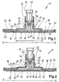
- a shower 11 according to the invention is shown.
- the showerhead 11 consists of a housing shell 12, which sits on a base 13 and is guided over this. By means of a lock nut 15, the shower head 11 is connected to a water connection 14 in a known ball head design.
- the water connection 14 sits, for example, on a ceiling.
- the housing shell 12 has approximately the shape of a tubular extension 17, which merges into the flat extension 18 downwards.
- the base 13 is formed, which widens also with an extension 24 downwards.
- the extension 24 of the base 13 has at the outer end a circumferential and downward annular shoulder 25. Its exact shape can be seen from Fig. 2. Down to goes the annular shoulder 25 in a narrow V-like profile over. In the position of FIG. 1, this serves the sealing effect. This will be discussed in more detail below.
- the showerhead 11 has a front side 27, which is connected to the housing shell 12 in the outside area.
- the front face 27 carries at its back the inserted jet disk 29.
- the jet disk 29 is made in a known manner from an elastomer and has molded nozzles for the formation of the outlet openings 30. From Fig. 1 and in particular Fig. 2 it can be seen that the back 31 of the jet disk 29 is substantially planar. Only the circumferential sealing lip 32 is integrally formed on the back 31. It can rest on the inside of the annular shoulder 25, as can be seen from Fig. 1.
- a water inlet 33 extends through the water connection 14 into the shower 11. From the ball head of the water connection 14 occurs the water through the openings 34, which are distributed around a central axis, in the upper part of the distribution chamber 36, which is located within the tube insert 17. As can be seen from Fig. 1, the water can reach due to the sealing concern of the expansion 24 with the adjacent annular shoulder 25 on the back 31 of the jet disk 29 lying only in this area outlet openings 30. Other river possibilities do not exist for the water. In particular, the outer area, ie area B without area A, is shut off.
- the distribution chamber 36 is fully open and now comprises the area of the openings 34 of the water inlet 33 over the entire surface of the back of the jet disk 29. Thus, the water can escape through all the outlet openings 30 of the jet disk 29.
- the shutter 42 is disengaged from the upper opening of the air channel 38.
- the air supply 40 from the front of the jet disk 29 and the front side 27 of the shower 11 in the shower or in the distribution chamber 36 into free.
- the air exiting from the upper opening of the air duct 38 passes approximately transversely to the water which shoots down through the openings 34 into the distribution chamber 36. Due to the Venturi effect, the incoming water entrains the air. At the same time, some mixing of water and air already begins.
- Verwirbelungsabsatz 46 which is integrally formed in the lower region of the outer side of the air channel 38.
- Verwirbelungsabsatzes 46 is here from the top impinging water to the side, ie in the lateral extent of the distribution chamber 36 into, deflected. But it is also achieved turbulence or mixing of the water-air mixture.
- the Verwirbelungsabsatz is formed stepwise with multiple stages. The course of the steps can correspond to the bevel.
- the course of the extension 24 of the base 13 is corresponding to the course of the extension 18 of the housing shell 12.
- the gradation in the extension 18 serves to provide room for the extension 24 entering this step. Furthermore, it limits the outer annular region of the distribution chamber 36 such that the water supply to all outlet openings 30 in the position of FIG. 2, ie when water is supplied to the entire area of the jet disk 29, is approximately equal.
- Fig. 2 it can be seen that it is possible under some circumstances, in addition to a more or less stage switching between the first area A and second area B and correspondingly between unventilated and ventilated, at least one of the function also adjustable to design. In particular, this offers the ventilation device.
- the shape of the lower part of the closure 42 and the corresponding opening in the upper part of the air duct 38 may be formed such that over the entire displacement of the relative movement between housing shell 12 and base 13, a continuous opening of the air supply 40 via the air paths 44 takes place. This can be even greater than when opening the distribution chamber 36.
- FIG. 3 shows a shower similar to the embodiment of FIGS. 1 and 2, but without a changeover device.
- an insert plate 50 is arranged, which with the outlet openings 30 of the jet disk 29 has corresponding openings 51.
- the insert plate is made of a harder plastic than the jet disk 29. It has, inter alia, the task of fixing the elastomer jet disk 29 on the front side 27 and on the bottom 52 of the housing. This is to prevent the beam angle of the individual jet outlet nipples from changing during operation or during assembly.
- the insert plate 50 On its rear side, the insert plate 50 contains individual ribs 53, which serve to subdivide the space between the jet disk and the rear wall 52 of the housing. This subdivision is intended to guide and direct the individual aerated jets within the housing.
- FIG. 4 shows another embodiment of a shower, which is particularly simple this time.
- the shower enclosure contains a rear wall 52 and a very simple jet disk 54, between which a very flat disc-like distribution chamber 55 is formed.
- the sealing takes place in the edge region by a groove 56 in the back 52 existing seal which rests on the back 56 of the jet disk 54, see Figure 6.
- the jet disk 54 is formed here from a total of a relatively hard plastic, so that the direction and Do not change the shape of the jet outlet openings 57.
- FIG. 5 represents an enlargement of the housing of FIG. 4, the jet outlet openings 57 are arranged obliquely and conically.
- the connection of the housing of the shower of Figure 3 and 4 with the water supply corresponds to that of Figure 1, so that these details will not be explained in detail.
- the water passing through the inlet now strikes a perforated disk 60 arranged transversely to the flow direction of the water, see the enlarged illustration in FIG. 7.
- the perforated disk 60 is circular and flat and has an edge flange running in the direction of flow 61 on.
- the opening 62 of the inlet has a significantly smaller diameter than the perforated disc 60.
- the arranged in the perforated disc 60 circular holes 63 are arranged along the circumference. The water must therefore first be deflected out of the opening 62 before it reaches the openings 63.
- FIG. 7 shows the embodiment of FIG. 3 on an enlarged scale.
- the inner end of the ventilation hub 64 is formed by a flat end surface 65. This is located at a small distance in front of or behind the perforated disc 60.
- the air sucked in through the central opening 40 of the ventilation hub 64 is directed as a very narrow, flat stream onto the already separated water jets. Due to the rapid flow of the water jets downstream of the holes 63 creates a Venturi effect, which sucks the air flow there.
- the aerated jets then pass along the cylindrical outer surface 66 of the breather hub 64 to the root 67 of the hub, where the outer side widens conically at an angle of, for example, about 45 degrees.
- This conical extension 67 rests on the insert plate 50, on which the water then flows radially in a plane further outward.
- the angle of the deflection 68 may be between 10 and 80 degrees. It is also conceivable a gradual curved Crossing.
- This deflection device serves to divert the aerated water jets produced radially outward into the distribution chamber arranged behind the jet disk.
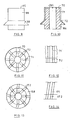
- Figure 8 shows very schematically the plan view of the perforated disc 60 with eight holes 63.
- the number of holes 63 is larger in order to produce the largest possible number of water jets. All holes 63 lie on a circle near the outer periphery of the perforated disc 60.
- FIG. 9 shows the ventilation hub 64 of FIG. 7 in a side view. It can clearly be seen that the deflection surface 68 extends over the entire circumference.
- the lateral surface 66 is smooth in the embodiment shown here.
- the face 65 also.
- FIGS. 10 to 12 show an embodiment of a ventilation hub 164 which is modified with respect to the ventilation hub 64.
- a plurality of radially extending channels 70 are formed in the end face 165 and lead from the interior 40 of the hub 164 to the outside.
- axial channels 71 are provided, which are formed by grooves.
- Each radial channel 70 merges into an axial channel 71.
- further channels 72 are formed in the extension of the channels 70 and 71, whose depth, see Figure 10, decreases to the end of the deflection 68. In this way, at the end face 165 of the ventilation hub 164 is ensured that individual air jets occur, which then hit the water jets formed there through the holes 63.
- Figures 13 and 14 show the corresponding representations in another ventilation hub, in which the channels 172 in the deflection 168 bent or curved run. This gives the aerated jets an oblique direction, which they maintain when leaving the ventilation hub. In this way, a turbulence of the ventilated jets is achieved within the distribution chamber of the showerhead.
- the channels 171 are not rectilinear parallel to the axis, as in the embodiment of Figure 12, but obliquely to the axis. So they run in the manner of a steep thread. This initiates the generation of a twist of the ventilated jets earlier.
- the ventilation hub 164 of FIG. 10 may be arranged, for example, such that the areas in the plane of the end face 165 between the channels 70 touch the perforated plate 60 on its underside. Then completely separate air jets are generated. However, it may also remain a certain distance, so that paths of preferred flow at the location of the channels 70 are generated.
- the baffles on the basis of the ventilation hubs can also be continued in the distribution chamber.
- the jet outlet openings can be arranged in a straight line extension of the projection of the channels 72, 172. Not all channels 72 and 172 need to have the same curvature or the same direction. It can be ensured that ventilated water jets, which are to be directed farther out in the distribution chamber, leave the foot of the ventilation hub in a more straight line, while the rays intended for the closer jet outlet openings are provided with greater turbulence.
- FIGS. 3 to 14 show, for reasons of simplified illustration, no switching device for switching over between different areas of the beam exit surface. They also show no means for switching on and off the ventilation device.
- the measures for the production and maintenance of individual ventilated jets are of course also possible and useful in showers in which such switching devices are available.
- the invention expressly proposes this.
Landscapes
- Health & Medical Sciences (AREA)
- Public Health (AREA)
- Life Sciences & Earth Sciences (AREA)
- Pain & Pain Management (AREA)
- Physical Education & Sports Medicine (AREA)
- Rehabilitation Therapy (AREA)
- Epidemiology (AREA)
- Animal Behavior & Ethology (AREA)
- General Health & Medical Sciences (AREA)
- Veterinary Medicine (AREA)
- Nozzles (AREA)
- Massaging Devices (AREA)
- Percussion Or Vibration Massage (AREA)
- Bathtubs, Showers, And Their Attachments (AREA)
- Details Or Accessories Of Spraying Plant Or Apparatus (AREA)
Priority Applications (1)
| Application Number | Priority Date | Filing Date | Title |
|---|---|---|---|
| SI200330771T SI1569756T1 (sl) | 2002-12-12 | 2003-12-12 | Prha z dovajanjem zraka |
Applications Claiming Priority (7)
| Application Number | Priority Date | Filing Date | Title |
|---|---|---|---|
| DE10259255 | 2002-12-12 | ||
| DE10259255 | 2002-12-12 | ||
| DE10313823A DE10313823A1 (de) | 2002-12-12 | 2003-03-24 | Brause |
| DE10313822 | 2003-03-24 | ||
| DE10313823 | 2003-03-24 | ||
| DE10313822A DE10313822A1 (de) | 2002-12-12 | 2003-03-24 | Brause |
| PCT/EP2003/014101 WO2004052550A1 (de) | 2002-12-12 | 2003-12-12 | Brause mit luftzuführung |
Publications (2)
| Publication Number | Publication Date |
|---|---|
| EP1569756A1 EP1569756A1 (de) | 2005-09-07 |
| EP1569756B1 true EP1569756B1 (de) | 2007-02-07 |
Family
ID=32511960
Family Applications (1)
| Application Number | Title | Priority Date | Filing Date |
|---|---|---|---|
| EP03789235A Expired - Lifetime EP1569756B1 (de) | 2002-12-12 | 2003-12-12 | Brause mit luftzuführung |
Country Status (9)
| Country | Link |
|---|---|
| US (1) | US7913934B2 (es) |
| EP (1) | EP1569756B1 (es) |
| JP (1) | JP4460532B2 (es) |
| AT (1) | ATE353250T1 (es) |
| AU (1) | AU2003293850A1 (es) |
| DE (1) | DE50306464D1 (es) |
| DK (1) | DK1569756T3 (es) |
| ES (1) | ES2281687T3 (es) |
| WO (1) | WO2004052550A1 (es) |
Cited By (1)
| Publication number | Priority date | Publication date | Assignee | Title |
|---|---|---|---|---|
| DE102017203577A1 (de) | 2016-03-07 | 2017-09-07 | Hansgrohe Se | Brausekopf für belüfteten Brausestrahl |
Families Citing this family (75)
| Publication number | Priority date | Publication date | Assignee | Title |
|---|---|---|---|---|
| US7114666B2 (en) | 2002-12-10 | 2006-10-03 | Water Pik, Inc. | Dual massage shower head |
| US7740186B2 (en) | 2004-09-01 | 2010-06-22 | Water Pik, Inc. | Drenching shower head |
| JP3937444B2 (ja) * | 2004-09-29 | 2007-06-27 | 東陶機器株式会社 | シャワーヘッド |
| DE102004059328A1 (de) * | 2004-12-01 | 2006-06-08 | Hansgrohe Ag | Brausekopf für eine Sanitärbrause |
| DE102004059329A1 (de) * | 2004-12-01 | 2006-06-08 | Hansgrohe Ag | Brausekopf für eine Sanitärbrause |
| ITBS20050128A1 (it) * | 2005-10-28 | 2007-04-29 | Nikles Tec Italia Srl | Soffione di doccia |
| ATE442909T1 (de) * | 2006-03-31 | 2009-10-15 | Crs Spa | Brausekopf |
| EP2007483A2 (en) | 2006-04-20 | 2008-12-31 | Water Pik, Inc. | Converging spray showerhead |
| JP5007306B2 (ja) * | 2006-09-05 | 2012-08-22 | 洋史 大熊 | シャワーヘッド |
| US7789326B2 (en) | 2006-12-29 | 2010-09-07 | Water Pik, Inc. | Handheld showerhead with mode control and method of selecting a handheld showerhead mode |
| US8020787B2 (en) | 2006-11-29 | 2011-09-20 | Water Pik, Inc. | Showerhead system |
| US7770822B2 (en) | 2006-12-28 | 2010-08-10 | Water Pik, Inc. | Hand shower with an extendable handle |
| US8794543B2 (en) | 2006-12-28 | 2014-08-05 | Water Pik, Inc. | Low-speed pulsating showerhead |
| US8366024B2 (en) | 2006-12-28 | 2013-02-05 | Water Pik, Inc. | Low speed pulsating showerhead |
| US8789218B2 (en) | 2007-05-04 | 2014-07-29 | Water Pik, Inc. | Molded arm for showerheads and method of making same |
| USD590048S1 (en) | 2007-12-20 | 2009-04-07 | Water Pik, Inc. | Hand shower |
| USD605731S1 (en) | 2007-12-26 | 2009-12-08 | Water Pik, Inc. | Bracket for hand shower |
| ITMI20080338A1 (it) * | 2008-02-29 | 2009-09-01 | Ergon Srl | Diffusore per doccia e relativi ugelli di erogazione |
| CN101249477B (zh) * | 2008-04-09 | 2010-06-23 | 周华松 | 花洒连接固定结构 |
| USD624156S1 (en) | 2008-04-30 | 2010-09-21 | Water Pik, Inc. | Pivot ball attachment |
| JP5197150B2 (ja) * | 2008-05-20 | 2013-05-15 | 株式会社Lixil | シャワーヘッド及びシャワー装置 |
| US8348181B2 (en) | 2008-09-15 | 2013-01-08 | Water Pik, Inc. | Shower assembly with radial mode changer |
| USD606623S1 (en) | 2008-09-29 | 2009-12-22 | Water Pik, Inc. | Hand shower |
| USD616061S1 (en) | 2008-09-29 | 2010-05-18 | Water Pik, Inc. | Showerhead assembly |
| USD600777S1 (en) | 2008-09-29 | 2009-09-22 | Water Pik, Inc. | Showerhead assembly |
| US9220376B2 (en) | 2008-12-17 | 2015-12-29 | Toto Ltd. | Shower apparatus |
| JP2010188046A (ja) * | 2009-02-20 | 2010-09-02 | Toto Ltd | シャワー装置 |
| IT1396495B1 (it) * | 2009-02-24 | 2012-12-14 | Nikles Tec Italia Srl | Dispositivo di erogazione di un getto d'acqua areato |
| IT1396875B1 (it) * | 2009-06-05 | 2012-12-20 | Bossini S P A | Soffione per doccia |
| US20110041940A1 (en) * | 2009-08-21 | 2011-02-24 | Chin-Tsai Lee | Seamless faucet and a manufacturing method thereof |
| USD625776S1 (en) | 2009-10-05 | 2010-10-19 | Water Pik, Inc. | Showerhead |
| JP5505700B2 (ja) | 2010-02-18 | 2014-05-28 | Toto株式会社 | シャワー装置 |
| JP5534416B2 (ja) | 2010-02-18 | 2014-07-02 | Toto株式会社 | シャワー装置 |
| JP5817967B2 (ja) * | 2010-06-23 | 2015-11-18 | Toto株式会社 | 吐水装置 |
| JP5633783B2 (ja) * | 2010-06-23 | 2014-12-03 | Toto株式会社 | シャワー装置 |
| US8616470B2 (en) | 2010-08-25 | 2013-12-31 | Water Pik, Inc. | Mode control valve in showerhead connector |
| US20120074178A1 (en) * | 2010-09-24 | 2012-03-29 | Jun Zhang | Dispensing device with multiple openings for bottle |
| US20120074179A1 (en) * | 2010-09-27 | 2012-03-29 | Allen & Thomas Cosmetic Accessories Co., Ltd. | Bottle with Multiple Openings |
| USD694366S1 (en) | 2011-01-14 | 2013-11-26 | Kohler Co. | Faucet |
| JP5854186B2 (ja) | 2011-03-14 | 2016-02-09 | Toto株式会社 | シャワー装置 |
| JP6115886B2 (ja) * | 2011-12-29 | 2017-04-19 | Toto株式会社 | シャワー装置 |
| USD678467S1 (en) | 2012-01-27 | 2013-03-19 | Water Pik, Inc. | Ring-shaped handheld showerhead |
| USD678463S1 (en) | 2012-01-27 | 2013-03-19 | Water Pik, Inc. | Ring-shaped wall mount showerhead |
| CA2898716C (en) | 2012-06-22 | 2020-02-11 | Water Pik, Inc. | Bracket for showerhead with integral flow control |
| DE102012213518B3 (de) | 2012-08-01 | 2013-11-21 | Hansgrohe Se | Brausekopf |
| DE102012216960A1 (de) | 2012-09-21 | 2014-03-27 | Hansgrohe Se | Brausekopf |
| US9546474B2 (en) | 2012-11-26 | 2017-01-17 | Kohler Co. | System, apparatus and method for creating and/or dispensing a mixture of water and a personal care liquid |
| US9004380B2 (en) * | 2013-04-15 | 2015-04-14 | Xiamen Fxy Bathroom Products Co., Ltd. | Shower head |
| WO2014201420A1 (en) | 2013-06-13 | 2014-12-18 | Water Pik, Inc. | Showerhead with turbine driven shutter |
| JP6124068B2 (ja) * | 2013-07-08 | 2017-05-10 | Toto株式会社 | キッチン用水栓 |
| JP6066339B2 (ja) * | 2014-03-31 | 2017-01-25 | Toto株式会社 | シャワー装置 |
| JP6032442B2 (ja) * | 2014-03-31 | 2016-11-30 | Toto株式会社 | シャワー装置 |
| JP6032440B2 (ja) * | 2014-03-31 | 2016-11-30 | Toto株式会社 | シャワー装置 |
| USD744614S1 (en) | 2014-06-13 | 2015-12-01 | Water Pik, Inc. | Wall mount showerhead |
| USD745111S1 (en) | 2014-06-13 | 2015-12-08 | Water Pik, Inc. | Wall mount showerhead |
| USD744066S1 (en) | 2014-06-13 | 2015-11-24 | Water Pik, Inc. | Wall mount showerhead |
| USD744065S1 (en) | 2014-06-13 | 2015-11-24 | Water Pik, Inc. | Handheld showerhead |
| USD744612S1 (en) | 2014-06-13 | 2015-12-01 | Water Pik, Inc. | Handheld showerhead |
| USD744064S1 (en) | 2014-06-13 | 2015-11-24 | Water Pik, Inc. | Handheld showerhead |
| EP3265234B1 (en) * | 2015-03-06 | 2021-04-14 | Husqvarna AB | Spraying apparatus |
| CN104923419B (zh) * | 2015-06-12 | 2017-03-29 | 福建欣宇卫浴科技股份有限公司 | 一种顶喷花洒按键切换结构及其应用的顶喷花洒 |
| EP3411155B1 (en) | 2016-02-01 | 2020-03-25 | Water Pik, Inc. | Handheld pet spray wand |
| USD803981S1 (en) | 2016-02-01 | 2017-11-28 | Water Pik, Inc. | Handheld spray nozzle |
| JP6706528B2 (ja) * | 2016-03-31 | 2020-06-10 | 株式会社Kvk | シャワーヘッド |
| US10265710B2 (en) | 2016-04-15 | 2019-04-23 | Water Pik, Inc. | Showerhead with dual oscillating massage |
| USD970684S1 (en) | 2016-04-15 | 2022-11-22 | Water Pik, Inc. | Showerhead |
| EP3669997B1 (en) | 2016-09-08 | 2022-10-12 | Water Pik, Inc. | Pause assembly for showerheads |
| CN108607699A (zh) * | 2016-12-19 | 2018-10-02 | 厦门松霖科技股份有限公司 | 残留水快排花洒 |
| CN110446547B (zh) * | 2017-04-05 | 2022-03-18 | 株式会社Toshin | 微气泡发生装置以及淋浴喷头 |
| USD843549S1 (en) | 2017-07-19 | 2019-03-19 | Water Pik, Inc. | Handheld spray nozzle |
| DE102018201109B3 (de) * | 2018-01-24 | 2018-12-27 | Hansgrohe Se | Brausekopf mit Überdruckventil |
| USD872227S1 (en) | 2018-04-20 | 2020-01-07 | Water Pik, Inc. | Handheld spray device |
| CN113135615A (zh) * | 2021-04-27 | 2021-07-20 | 普利资环境科技(苏州)有限公司 | 一种防堵塞曝气喷头 |
| RU207454U1 (ru) * | 2021-07-06 | 2021-10-28 | Общество с ограниченной ответственностью "ВЕГА" (ООО "ВЕГА") | Распылительная форсунка насадки огнетушителя |
| WO2023039495A1 (en) * | 2021-09-10 | 2023-03-16 | As America, Inc. | Showerhead assembly with aeration |
Family Cites Families (14)
| Publication number | Priority date | Publication date | Assignee | Title |
|---|---|---|---|---|
| FR663556A (fr) * | 1927-11-09 | 1929-08-22 | Instrument d'arrosage pour opérations de massage | |
| US3633824A (en) * | 1969-07-08 | 1972-01-11 | Elic P Aghnides | Spray-producing device in which the output jets are aerated |
| US3796377A (en) * | 1972-06-01 | 1974-03-12 | Federal Investment Corp | Combination aerator and shower nozzle |
| JPS5286858A (en) | 1976-01-10 | 1977-07-19 | Tsd Kk | Shower |
| DE2821195A1 (de) | 1978-05-13 | 1979-11-15 | Guenther Rathsack Ingenieurtec | Handbrause |
| DE3413552A1 (de) | 1984-04-11 | 1985-10-24 | Hansa Metallwerke Ag, 7000 Stuttgart | Brause |
| US5111994A (en) * | 1987-07-30 | 1992-05-12 | Emhart Inc. | Flow booster apparatus |
| US5154355A (en) | 1987-07-30 | 1992-10-13 | Emhart Inc. | Flow booster apparatus |
| JP2769021B2 (ja) | 1990-03-30 | 1998-06-25 | 東陶機器株式会社 | 吐水口 |
| JPH047051A (ja) | 1990-04-23 | 1992-01-10 | Toto Ltd | 吐水ヘッド |
| JP2528371Y2 (ja) | 1993-12-06 | 1997-03-12 | 株式会社ナニワ製作所 | 泡沫状吐水兼用のシャワーヘッド |
| JP2962254B2 (ja) | 1996-12-26 | 1999-10-12 | 松下電器産業株式会社 | 湯水吐出装置 |
| US6270022B1 (en) * | 1997-06-03 | 2001-08-07 | Masco Corporation | Multiple jet shower with aeration device |
| DE10103649B4 (de) | 2001-01-27 | 2007-12-06 | Hansgrohe Ag | Brausekopf |
-
2003
- 2003-12-12 AU AU2003293850A patent/AU2003293850A1/en not_active Abandoned
- 2003-12-12 WO PCT/EP2003/014101 patent/WO2004052550A1/de not_active Ceased
- 2003-12-12 DE DE50306464T patent/DE50306464D1/de not_active Expired - Lifetime
- 2003-12-12 ES ES03789235T patent/ES2281687T3/es not_active Expired - Lifetime
- 2003-12-12 US US10/538,398 patent/US7913934B2/en not_active Expired - Fee Related
- 2003-12-12 JP JP2005502320A patent/JP4460532B2/ja not_active Expired - Fee Related
- 2003-12-12 AT AT03789235T patent/ATE353250T1/de active
- 2003-12-12 EP EP03789235A patent/EP1569756B1/de not_active Expired - Lifetime
- 2003-12-12 DK DK03789235T patent/DK1569756T3/da active
Cited By (2)
| Publication number | Priority date | Publication date | Assignee | Title |
|---|---|---|---|---|
| DE102017203577A1 (de) | 2016-03-07 | 2017-09-07 | Hansgrohe Se | Brausekopf für belüfteten Brausestrahl |
| DE102017203577B4 (de) | 2016-03-07 | 2019-08-08 | Hansgrohe Se | Brausekopf für belüfteten Brausestrahl |
Also Published As
| Publication number | Publication date |
|---|---|
| JP4460532B2 (ja) | 2010-05-12 |
| AU2003293850A1 (en) | 2004-06-30 |
| US7913934B2 (en) | 2011-03-29 |
| ES2281687T3 (es) | 2007-10-01 |
| EP1569756A1 (de) | 2005-09-07 |
| DK1569756T3 (da) | 2007-06-04 |
| US20060163391A1 (en) | 2006-07-27 |
| DE50306464D1 (de) | 2007-03-22 |
| ATE353250T1 (de) | 2007-02-15 |
| JP2006509629A (ja) | 2006-03-23 |
| WO2004052550A1 (de) | 2004-06-24 |
Similar Documents
| Publication | Publication Date | Title |
|---|---|---|
| EP1569756B1 (de) | Brause mit luftzuführung | |
| DE10313822A1 (de) | Brause | |
| EP0719587B1 (de) | Brausekopf, insbesondere für eine Handbrause | |
| EP1928609B1 (de) | Duschkopf | |
| EP0646680B1 (de) | Strahlregler zum Anschluss an Sanitärarmaturen | |
| DE3640497C2 (es) | ||
| DE2140526C3 (de) | Sprühkopf für eine Brause oder dgl | |
| EP2550410B1 (de) | Strahlregler | |
| EP0151998A2 (de) | Wasserstrahlbelüfter für Sanitär-Armaturen und dergleichen | |
| DE112012005017B4 (de) | Vorrichtung zum Steuern einer Fluid-Strömung in einem Notfall-Waschsystem, Vorrichtung zum Steuern einer Fluid-Strömung und Waschsystem zum Liefern einer Fluid-Strömung | |
| DE3740714A1 (de) | Luftstromverteiler | |
| DE69838907T2 (de) | Mehrfachstrahldusche mit luftzumischung | |
| CH664507A5 (de) | Brause. | |
| DE102013004076B4 (de) | Strahlregler mit Prallfläche und Ringwandung | |
| EP3009571B1 (de) | Strahlregler | |
| EP2971385A1 (de) | Strahlregler umfassend eine prallfläche mit ringwandungen | |
| EP3848518A1 (de) | Sanitäre auslaufeinheit | |
| DE3110029C2 (es) | ||
| DE4118540A1 (de) | Handbrause | |
| DE69915582T2 (de) | Brause mit Düsen für Wassersprühstrahlen | |
| DE102016211645B3 (de) | Brauseumstellventil und Sanitärbrause | |
| DE10005686A1 (de) | Brausekopf | |
| DE102016213489B3 (de) | Brausenumschaltventil und Sanitärbrause | |
| DE3720918C1 (en) | Steam reducing valve | |
| DE2408403A1 (de) | Auslauftuelle fuer wasserhaehne |
Legal Events
| Date | Code | Title | Description |
|---|---|---|---|
| PUAI | Public reference made under article 153(3) epc to a published international application that has entered the european phase |
Free format text: ORIGINAL CODE: 0009012 |
|
| 17P | Request for examination filed |
Effective date: 20050524 |
|
| AK | Designated contracting states |
Kind code of ref document: A1 Designated state(s): AT BE BG CH CY CZ DE DK EE ES FI FR GB GR HU IE IT LI LU MC NL PT RO SE SI SK TR |
|
| AX | Request for extension of the european patent |
Extension state: AL LT LV MK |
|
| DAX | Request for extension of the european patent (deleted) | ||
| GRAP | Despatch of communication of intention to grant a patent |
Free format text: ORIGINAL CODE: EPIDOSNIGR1 |
|
| GRAS | Grant fee paid |
Free format text: ORIGINAL CODE: EPIDOSNIGR3 |
|
| GRAA | (expected) grant |
Free format text: ORIGINAL CODE: 0009210 |
|
| AK | Designated contracting states |
Kind code of ref document: B1 Designated state(s): AT BE BG CH CY CZ DE DK EE ES FI FR GB GR HU IE IT LI LU MC NL PT RO SE SI SK TR |
|
| PG25 | Lapsed in a contracting state [announced via postgrant information from national office to epo] |
Ref country code: IE Free format text: LAPSE BECAUSE OF FAILURE TO SUBMIT A TRANSLATION OF THE DESCRIPTION OR TO PAY THE FEE WITHIN THE PRESCRIBED TIME-LIMIT Effective date: 20070207 |
|
| REG | Reference to a national code |
Ref country code: GB Ref legal event code: FG4D Free format text: NOT ENGLISH |
|
| REG | Reference to a national code |
Ref country code: CH Ref legal event code: NV Representative=s name: TROESCH SCHEIDEGGER WERNER AG Ref country code: CH Ref legal event code: EP |
|
| REG | Reference to a national code |
Ref country code: IE Ref legal event code: FG4D Free format text: LANGUAGE OF EP DOCUMENT: GERMAN |
|
| REF | Corresponds to: |
Ref document number: 50306464 Country of ref document: DE Date of ref document: 20070322 Kind code of ref document: P |
|
| REG | Reference to a national code |
Ref country code: PT Ref legal event code: SC4A Free format text: AVAILABILITY OF NATIONAL TRANSLATION Effective date: 20070309 |
|
| GBT | Gb: translation of ep patent filed (gb section 77(6)(a)/1977) |
Effective date: 20070411 |
|
| REG | Reference to a national code |
Ref country code: SE Ref legal event code: TRGR |
|
| REG | Reference to a national code |
Ref country code: EE Ref legal event code: FG4A Ref document number: E001047 Country of ref document: EE Effective date: 20070507 |
|
| ET | Fr: translation filed | ||
| REG | Reference to a national code |
Ref country code: IE Ref legal event code: FD4D |
|
| REG | Reference to a national code |
Ref country code: ES Ref legal event code: FG2A Ref document number: 2281687 Country of ref document: ES Kind code of ref document: T3 |
|
| PLBE | No opposition filed within time limit |
Free format text: ORIGINAL CODE: 0009261 |
|
| STAA | Information on the status of an ep patent application or granted ep patent |
Free format text: STATUS: NO OPPOSITION FILED WITHIN TIME LIMIT |
|
| PG25 | Lapsed in a contracting state [announced via postgrant information from national office to epo] |
Ref country code: RO Free format text: LAPSE BECAUSE OF FAILURE TO SUBMIT A TRANSLATION OF THE DESCRIPTION OR TO PAY THE FEE WITHIN THE PRESCRIBED TIME-LIMIT Effective date: 20070207 |
|
| 26N | No opposition filed |
Effective date: 20071108 |
|
| PG25 | Lapsed in a contracting state [announced via postgrant information from national office to epo] |
Ref country code: GR Free format text: LAPSE BECAUSE OF FAILURE TO SUBMIT A TRANSLATION OF THE DESCRIPTION OR TO PAY THE FEE WITHIN THE PRESCRIBED TIME-LIMIT Effective date: 20070508 |
|
| PG25 | Lapsed in a contracting state [announced via postgrant information from national office to epo] |
Ref country code: MC Free format text: LAPSE BECAUSE OF NON-PAYMENT OF DUE FEES Effective date: 20071231 |
|
| PGFP | Annual fee paid to national office [announced via postgrant information from national office to epo] |
Ref country code: EE Payment date: 20081219 Year of fee payment: 6 |
|
| PGFP | Annual fee paid to national office [announced via postgrant information from national office to epo] |
Ref country code: FI Payment date: 20081222 Year of fee payment: 6 Ref country code: PT Payment date: 20081204 Year of fee payment: 6 Ref country code: SK Payment date: 20081208 Year of fee payment: 6 |
|
| PGFP | Annual fee paid to national office [announced via postgrant information from national office to epo] |
Ref country code: SE Payment date: 20081222 Year of fee payment: 6 |
|
| PGFP | Annual fee paid to national office [announced via postgrant information from national office to epo] |
Ref country code: SI Payment date: 20081203 Year of fee payment: 6 |
|
| PG25 | Lapsed in a contracting state [announced via postgrant information from national office to epo] |
Ref country code: CY Free format text: LAPSE BECAUSE OF FAILURE TO SUBMIT A TRANSLATION OF THE DESCRIPTION OR TO PAY THE FEE WITHIN THE PRESCRIBED TIME-LIMIT Effective date: 20070207 |
|
| PG25 | Lapsed in a contracting state [announced via postgrant information from national office to epo] |
Ref country code: LU Free format text: LAPSE BECAUSE OF NON-PAYMENT OF DUE FEES Effective date: 20071212 |
|
| PG25 | Lapsed in a contracting state [announced via postgrant information from national office to epo] |
Ref country code: HU Free format text: LAPSE BECAUSE OF FAILURE TO SUBMIT A TRANSLATION OF THE DESCRIPTION OR TO PAY THE FEE WITHIN THE PRESCRIBED TIME-LIMIT Effective date: 20070808 |
|
| REG | Reference to a national code |
Ref country code: PT Ref legal event code: MM4A Free format text: LAPSE DUE TO NON-PAYMENT OF FEES Effective date: 20100614 |
|
| EUG | Se: european patent has lapsed | ||
| PG25 | Lapsed in a contracting state [announced via postgrant information from national office to epo] |
Ref country code: PT Free format text: LAPSE BECAUSE OF NON-PAYMENT OF DUE FEES Effective date: 20100614 |
|
| REG | Reference to a national code |
Ref country code: EE Ref legal event code: MM4A Ref document number: E001047 Country of ref document: EE Effective date: 20091231 |
|
| PG25 | Lapsed in a contracting state [announced via postgrant information from national office to epo] |
Ref country code: FI Free format text: LAPSE BECAUSE OF NON-PAYMENT OF DUE FEES Effective date: 20091212 |
|
| REG | Reference to a national code |
Ref country code: SI Ref legal event code: KO00 Effective date: 20100719 |
|
| REG | Reference to a national code |
Ref country code: SK Ref legal event code: MM4A Ref document number: E 1813 Country of ref document: SK Effective date: 20091212 |
|
| PG25 | Lapsed in a contracting state [announced via postgrant information from national office to epo] |
Ref country code: EE Free format text: LAPSE BECAUSE OF NON-PAYMENT OF DUE FEES Effective date: 20091231 |
|
| PG25 | Lapsed in a contracting state [announced via postgrant information from national office to epo] |
Ref country code: SI Free format text: LAPSE BECAUSE OF NON-PAYMENT OF DUE FEES Effective date: 20091213 Ref country code: SK Free format text: LAPSE BECAUSE OF NON-PAYMENT OF DUE FEES Effective date: 20091212 |
|
| PG25 | Lapsed in a contracting state [announced via postgrant information from national office to epo] |
Ref country code: SE Free format text: LAPSE BECAUSE OF NON-PAYMENT OF DUE FEES Effective date: 20091213 |
|
| REG | Reference to a national code |
Ref country code: DE Ref legal event code: R082 Ref document number: 50306464 Country of ref document: DE Representative=s name: PATENTANWAELTE RUFF, WILHELM, BEIER, DAUSTER &, DE |
|
| REG | Reference to a national code |
Ref country code: DE Ref legal event code: R081 Ref document number: 50306464 Country of ref document: DE Owner name: HANSGROHE SE, DE Free format text: FORMER OWNER: HANSGROHE AG, 77761 SCHILTACH, DE Effective date: 20120910 Ref country code: DE Ref legal event code: R082 Ref document number: 50306464 Country of ref document: DE Representative=s name: PATENTANWAELTE RUFF, WILHELM, BEIER, DAUSTER &, DE Effective date: 20120910 |
|
| PGFP | Annual fee paid to national office [announced via postgrant information from national office to epo] |
Ref country code: BG Payment date: 20141229 Year of fee payment: 12 Ref country code: CZ Payment date: 20141203 Year of fee payment: 12 |
|
| REG | Reference to a national code |
Ref country code: FR Ref legal event code: PLFP Year of fee payment: 13 |
|
| PGFP | Annual fee paid to national office [announced via postgrant information from national office to epo] |
Ref country code: CH Payment date: 20151222 Year of fee payment: 13 Ref country code: GB Payment date: 20151221 Year of fee payment: 13 Ref country code: DK Payment date: 20151221 Year of fee payment: 13 |
|
| PGFP | Annual fee paid to national office [announced via postgrant information from national office to epo] |
Ref country code: NL Payment date: 20151221 Year of fee payment: 13 Ref country code: AT Payment date: 20151217 Year of fee payment: 13 Ref country code: ES Payment date: 20151218 Year of fee payment: 13 Ref country code: BE Payment date: 20151221 Year of fee payment: 13 Ref country code: FR Payment date: 20151218 Year of fee payment: 13 |
|
| PGFP | Annual fee paid to national office [announced via postgrant information from national office to epo] |
Ref country code: DE Payment date: 20151228 Year of fee payment: 13 |
|
| PG25 | Lapsed in a contracting state [announced via postgrant information from national office to epo] |
Ref country code: CZ Free format text: LAPSE BECAUSE OF NON-PAYMENT OF DUE FEES Effective date: 20151212 |
|
| PGFP | Annual fee paid to national office [announced via postgrant information from national office to epo] |
Ref country code: IT Payment date: 20151222 Year of fee payment: 13 |
|
| PG25 | Lapsed in a contracting state [announced via postgrant information from national office to epo] |
Ref country code: BG Free format text: LAPSE BECAUSE OF NON-PAYMENT OF DUE FEES Effective date: 20160930 |
|
| PG25 | Lapsed in a contracting state [announced via postgrant information from national office to epo] |
Ref country code: BE Free format text: LAPSE BECAUSE OF NON-PAYMENT OF DUE FEES Effective date: 20161231 |
|
| REG | Reference to a national code |
Ref country code: DE Ref legal event code: R119 Ref document number: 50306464 Country of ref document: DE |
|
| REG | Reference to a national code |
Ref country code: DK Ref legal event code: EBP Effective date: 20161231 Ref country code: CH Ref legal event code: PL |
|
| REG | Reference to a national code |
Ref country code: NL Ref legal event code: MM Effective date: 20170101 |
|
| REG | Reference to a national code |
Ref country code: AT Ref legal event code: MM01 Ref document number: 353250 Country of ref document: AT Kind code of ref document: T Effective date: 20161212 |
|
| GBPC | Gb: european patent ceased through non-payment of renewal fee |
Effective date: 20161212 |
|
| PG25 | Lapsed in a contracting state [announced via postgrant information from national office to epo] |
Ref country code: NL Free format text: LAPSE BECAUSE OF NON-PAYMENT OF DUE FEES Effective date: 20170101 |
|
| REG | Reference to a national code |
Ref country code: FR Ref legal event code: ST Effective date: 20170831 |
|
| PG25 | Lapsed in a contracting state [announced via postgrant information from national office to epo] |
Ref country code: FR Free format text: LAPSE BECAUSE OF NON-PAYMENT OF DUE FEES Effective date: 20170102 Ref country code: LI Free format text: LAPSE BECAUSE OF NON-PAYMENT OF DUE FEES Effective date: 20161231 Ref country code: CH Free format text: LAPSE BECAUSE OF NON-PAYMENT OF DUE FEES Effective date: 20161231 Ref country code: AT Free format text: LAPSE BECAUSE OF NON-PAYMENT OF DUE FEES Effective date: 20161212 Ref country code: IT Free format text: LAPSE BECAUSE OF NON-PAYMENT OF DUE FEES Effective date: 20161212 |
|
| PG25 | Lapsed in a contracting state [announced via postgrant information from national office to epo] |
Ref country code: GB Free format text: LAPSE BECAUSE OF NON-PAYMENT OF DUE FEES Effective date: 20161212 Ref country code: DE Free format text: LAPSE BECAUSE OF NON-PAYMENT OF DUE FEES Effective date: 20170701 |
|
| PGFP | Annual fee paid to national office [announced via postgrant information from national office to epo] |
Ref country code: TR Payment date: 20151212 Year of fee payment: 13 |
|
| PG25 | Lapsed in a contracting state [announced via postgrant information from national office to epo] |
Ref country code: DK Free format text: LAPSE BECAUSE OF NON-PAYMENT OF DUE FEES Effective date: 20161231 |
|
| REG | Reference to a national code |
Ref country code: BE Ref legal event code: MM Effective date: 20161231 |
|
| PG25 | Lapsed in a contracting state [announced via postgrant information from national office to epo] |
Ref country code: ES Free format text: LAPSE BECAUSE OF NON-PAYMENT OF DUE FEES Effective date: 20161213 |
|
| REG | Reference to a national code |
Ref country code: ES Ref legal event code: FD2A Effective date: 20181116 |
|
| PG25 | Lapsed in a contracting state [announced via postgrant information from national office to epo] |
Ref country code: TR Free format text: LAPSE BECAUSE OF NON-PAYMENT OF DUE FEES Effective date: 20161212 |