EP1569756B1 - Shower head with air introduction - Google Patents
Shower head with air introduction Download PDFInfo
- Publication number
- EP1569756B1 EP1569756B1 EP03789235A EP03789235A EP1569756B1 EP 1569756 B1 EP1569756 B1 EP 1569756B1 EP 03789235 A EP03789235 A EP 03789235A EP 03789235 A EP03789235 A EP 03789235A EP 1569756 B1 EP1569756 B1 EP 1569756B1
- Authority
- EP
- European Patent Office
- Prior art keywords
- water
- shower outlet
- shower
- outlet according
- jet
- Prior art date
- Legal status (The legal status is an assumption and is not a legal conclusion. Google has not performed a legal analysis and makes no representation as to the accuracy of the status listed.)
- Expired - Lifetime
Links
- XLYOFNOQVPJJNP-UHFFFAOYSA-N water Substances O XLYOFNOQVPJJNP-UHFFFAOYSA-N 0.000 claims abstract description 116
- 238000009826 distribution Methods 0.000 claims description 42
- 238000007789 sealing Methods 0.000 claims description 8
- 230000015572 biosynthetic process Effects 0.000 claims description 7
- 229920001971 elastomer Polymers 0.000 claims description 6
- 239000000806 elastomer Substances 0.000 claims description 4
- 238000009434 installation Methods 0.000 claims description 4
- 230000004913 activation Effects 0.000 claims description 3
- 239000013013 elastic material Substances 0.000 claims description 2
- 230000007704 transition Effects 0.000 claims description 2
- 238000009827 uniform distribution Methods 0.000 claims description 2
- 239000007921 spray Substances 0.000 claims 16
- 238000005273 aeration Methods 0.000 claims 12
- 230000008707 rearrangement Effects 0.000 claims 1
- 238000011144 upstream manufacturing Methods 0.000 claims 1
- 238000009423 ventilation Methods 0.000 description 29
- 230000000694 effects Effects 0.000 description 7
- 230000008901 benefit Effects 0.000 description 4
- 230000008859 change Effects 0.000 description 3
- 239000000203 mixture Substances 0.000 description 3
- 239000004033 plastic Substances 0.000 description 2
- 238000000926 separation method Methods 0.000 description 2
- 229910000831 Steel Inorganic materials 0.000 description 1
- 230000003213 activating effect Effects 0.000 description 1
- 230000009286 beneficial effect Effects 0.000 description 1
- 239000003795 chemical substances by application Substances 0.000 description 1
- 230000007423 decrease Effects 0.000 description 1
- 230000001419 dependent effect Effects 0.000 description 1
- 238000006073 displacement reaction Methods 0.000 description 1
- 230000009977 dual effect Effects 0.000 description 1
- 238000012423 maintenance Methods 0.000 description 1
- 238000004519 manufacturing process Methods 0.000 description 1
- 230000013011 mating Effects 0.000 description 1
- 238000000034 method Methods 0.000 description 1
- 210000002445 nipple Anatomy 0.000 description 1
- 238000003825 pressing Methods 0.000 description 1
- 230000008569 process Effects 0.000 description 1
- 239000010959 steel Substances 0.000 description 1
- 230000001960 triggered effect Effects 0.000 description 1
Images


Classifications
-
- B—PERFORMING OPERATIONS; TRANSPORTING
- B05—SPRAYING OR ATOMISING IN GENERAL; APPLYING FLUENT MATERIALS TO SURFACES, IN GENERAL
- B05B—SPRAYING APPARATUS; ATOMISING APPARATUS; NOZZLES
- B05B7/00—Spraying apparatus for discharge of liquids or other fluent materials from two or more sources, e.g. of liquid and air, of powder and gas
- B05B7/02—Spray pistols; Apparatus for discharge
- B05B7/04—Spray pistols; Apparatus for discharge with arrangements for mixing liquids or other fluent materials before discharge
- B05B7/0416—Spray pistols; Apparatus for discharge with arrangements for mixing liquids or other fluent materials before discharge with arrangements for mixing one gas and one liquid
- B05B7/0425—Spray pistols; Apparatus for discharge with arrangements for mixing liquids or other fluent materials before discharge with arrangements for mixing one gas and one liquid without any source of compressed gas, e.g. the air being sucked by the pressurised liquid
-
- A—HUMAN NECESSITIES
- A61—MEDICAL OR VETERINARY SCIENCE; HYGIENE
- A61H—PHYSICAL THERAPY APPARATUS, e.g. DEVICES FOR LOCATING OR STIMULATING REFLEX POINTS IN THE BODY; ARTIFICIAL RESPIRATION; MASSAGE; BATHING DEVICES FOR SPECIAL THERAPEUTIC OR HYGIENIC PURPOSES OR SPECIFIC PARTS OF THE BODY
- A61H33/00—Bathing devices for special therapeutic or hygienic purposes
- A61H33/02—Bathing devices for use with gas-containing liquid, or liquid in which gas is led or generated, e.g. carbon dioxide baths
- A61H33/027—Gas-water mixing nozzles therefor
-
- A—HUMAN NECESSITIES
- A61—MEDICAL OR VETERINARY SCIENCE; HYGIENE
- A61H—PHYSICAL THERAPY APPARATUS, e.g. DEVICES FOR LOCATING OR STIMULATING REFLEX POINTS IN THE BODY; ARTIFICIAL RESPIRATION; MASSAGE; BATHING DEVICES FOR SPECIAL THERAPEUTIC OR HYGIENIC PURPOSES OR SPECIFIC PARTS OF THE BODY
- A61H33/00—Bathing devices for special therapeutic or hygienic purposes
- A61H33/60—Components specifically designed for the therapeutic baths of groups A61H33/00
- A61H33/601—Inlet to the bath
- A61H33/6021—Nozzles
- A61H33/6052—Having flow regulating means
-
- B—PERFORMING OPERATIONS; TRANSPORTING
- B05—SPRAYING OR ATOMISING IN GENERAL; APPLYING FLUENT MATERIALS TO SURFACES, IN GENERAL
- B05B—SPRAYING APPARATUS; ATOMISING APPARATUS; NOZZLES
- B05B1/00—Nozzles, spray heads or other outlets, with or without auxiliary devices such as valves, heating means
- B05B1/14—Nozzles, spray heads or other outlets, with or without auxiliary devices such as valves, heating means with multiple outlet openings; with strainers in or outside the outlet opening
- B05B1/16—Nozzles, spray heads or other outlets, with or without auxiliary devices such as valves, heating means with multiple outlet openings; with strainers in or outside the outlet opening having selectively- effective outlets
- B05B1/1609—Nozzles, spray heads or other outlets, with or without auxiliary devices such as valves, heating means with multiple outlet openings; with strainers in or outside the outlet opening having selectively- effective outlets with a selecting mechanism comprising a lift valve
-
- B—PERFORMING OPERATIONS; TRANSPORTING
- B05—SPRAYING OR ATOMISING IN GENERAL; APPLYING FLUENT MATERIALS TO SURFACES, IN GENERAL
- B05B—SPRAYING APPARATUS; ATOMISING APPARATUS; NOZZLES
- B05B1/00—Nozzles, spray heads or other outlets, with or without auxiliary devices such as valves, heating means
- B05B1/14—Nozzles, spray heads or other outlets, with or without auxiliary devices such as valves, heating means with multiple outlet openings; with strainers in or outside the outlet opening
- B05B1/18—Roses; Shower heads
- B05B1/185—Roses; Shower heads characterised by their outlet element; Mounting arrangements therefor
Definitions
- the invention relates to a shower with a housing and a beam exit surface of the housing.
- the jet exit surface has a plurality of outlet openings.
- Such showers have long been known in many forms and have many functional possibilities.
- the invention has for its object to provide an aforementioned shower with functional capabilities that are not yet known in the art and in particular allow a beneficial use.
- a shower head which also has two chambers behind the jet disk, namely an inner chamber and an outer chamber.
- the water in the inner chamber is vented through openings between the shower head and its attachment.
- the aerated water enters the outer chamber through openings in the dividing wall.
- the non-directional water flows ventilated from all the beam outlet openings (DE 3825537).
- the shower contains a housing which is closed off to the user side by a jet disk.
- This jet disc contains a plurality of jet outlets, which may be specially designed by certain arrangements.
- the shower contains a flat large housing.
- the ventilation device can be designed such that it introduces the air through the jet exit disk into the housing, for example directly in the middle in the preferably flat jet disk.
- the showerhead according to the invention may further comprise a jet forming means for forming a plurality of individual water jets within the housing.
- the individual water jets are therefore not formed when leaving the shower. In this way, it is possible to perform certain processes within the housing with the water jets.
- the ventilation device may be formed in a development of the invention such that it aerates the water in front of the beam forming agent. Then, the jet-forming means serves to form a ventilated jet of individual aerated jets, which are then distributed within the showerhead, for example, to a surface having a large diameter relative to the water inlet, for example, a diameter of 10 to 20 times larger ,
- the beam-forming means and / or the ventilation device is designed such that the individual beams already formed are ventilated jointly and / or separately. This makes it possible to not have to consider the subsequent ventilation in the formation of water jets.
- the shower can have guiding means to guide the aerated water jets to the jet outlet openings of the entire jet disk, preferably evenly, but also unevenly as desired.
- the guide means can be arranged at different points of the shower, for example in the distribution chamber, which is formed directly behind the jet disk.
- the conducting means can also be arranged where the formed rays are aerated or the aerated rays are formed.
- the conducting means and / or the ventilating device may be designed such that they produce a turbulence of the ventilated jets. This laid is successful, inter alia, is suitable to increase the residence time of the beams within the shower enclosure, in order to achieve in this way a longer and / or more intensive contact with him the shower enclosure existing facilities.
- the ventilation device may be formed in a further development of the invention so that it generates an air flow that meets perpendicular to the flow of water, where they, as already mentioned, can meet already formed individual water jets.
- the ventilation device such that it already generates individual air jets or air flows, which then already meet the water flow separately.
- each air jet is assigned to a water jet, which it encounters. Complete or partial separation of air currents and water flows in the housing may be performed. It is thereby possible to ventilate the individual water jets different degrees or at a different location.
- the jet-forming means may comprise, for example, a perforated disc which is arranged transversely to the water flow. Through each hole then a jet of water is generated.
- These water jets can, as already mentioned, either be completely separated or else only partially separated so that different individual flow threads develop within a common water volume.
- the ventilation device may comprise a central sleeve or hub, through whose interior the air passes from the outside into the interior of the housing.
- the hub may, for example, have a smooth end surface, which forms with a corresponding mating surface a flat annular space through which the air flow is directed to the water.
- this front end radial air ducts such as grooves, which lead to a separation of the air flow.
- the end of the radial air ducts is aligned with the openings of the perforated disc.
- the orientation may be such that the centerline of the grooves is toward the center of the apertures.
- a tangential orientation is given, so that the center line of the grooves extends off-center to tangentially to the openings of the perforated disc.
- the air ducts can run exactly radially or slightly obliquely.
- the hub at the inner end of which the air flows substantially radially in a plane to the longitudinal axis, may also contain guides for the aerated jets on its outer circumferential surface, which lies in a cylindrical surface. These guides may be the grooves aligned with the holes in the perforated disc are. These guides serve to separate the aerated jets as they travel further within the showerhead, that is, to retard or hinder their reunification.
- the grooves may extend primarily in the axial direction, but they may also be slightly oblique, for example in the manner of a coarse thread.
- a deflection by a corresponding conical design of the outside of the hub can take place.
- This deflection may also be gradual, for example, by the outer side of the hub transitioning into a radial plane in a curved shape.
- This curved shape or the gradual transition or the deflection can also be done independently of the presence of axial water ducts.
- the deflection means may also, depending on the desired purpose, have individual channels, which may then be straight linear, oblique or curved.
- guide means may be arranged, which may be aligned with the direction of the deflection means. This is to achieve a good distribution of the aerated water jets over the entire surface of the jet disk.
- the guide means may be present, for example, on the back of the housing or on an insert in the housing.
- a showerhead in addition to a housing and a beam exit surface with outlet openings and a subdivision have in at least two areas a switching device.
- the water supply can be switched between a first area and a second area.
- a water access is provided in the shower, which ensures the supply of water into the shower.
- An air supply device is provided for ventilation of the water jets emerging from the shower. By means of the air supply device, the water supply is ventilated, namely between water inlet and jet exit surface.
- the air supply device can be activated and deactivated, so it can be switched.
- the changeover device and the air supply device according to the invention are coupled to one another in such a way that upon actuation of the changeover device the air supply is switched from activated to deactivated or from deactivated to activated.
- the air supply means changes its activation state when switching from the first to the second area.
- a double function is given when the changeover device is actuated.
- the direction of actuation could also be the other way round, ie when activating or deactivating the air supply device, a change from one area to the other.
- the air supply device With a single operation, two functions are triggered. Above all, it is possible to combine the function of the air supply device with respect to activated or deactivated with the selection of the areas or to make it dependent.
- the first region As a partial region of the beam exit surface, wherein it may be, for example, a central region.
- the second beam area As the second area.
- the air supply can be activated when the changeover device is placed on the second region or on the entire steel exit surface. This has the advantage that by the air supply or ventilation the water jets, a voluminous appearing water outlet can be created, which is just in the increased number of outlet openings in the case of a larger area of advantage.
- the switching device is advantageous operable by hand.
- a button or slider or the like can be pressed.
- an entire and in particular larger housing part can be moved relative to another housing part or the rest of the housing.
- the two areas or all areas can be connected via a distribution chamber with the water inlet for the water supply.
- the distribution chamber can advantageously extend over the surface of all regions or the rear side of the jet exit surface. This ensures a good water supply for all areas and all the jet outlet openings of the jet outlet area.
- the changeover device can be designed such that it is arranged in the distribution chamber and acts. When setting to the first area, it can limit the distribution chamber to the area corresponding to the first area. When switching to another area or the second area, the boundary of the distribution chamber is adapted to the area of this wider area. If the entire beam exit surface is changed over, the boundary of the distribution chamber can be removed, so that it extends over the entire beam exit surface.
- the changeover device may have a closure, which may be particularly preferably designed to limit the distribution chamber.
- a limitation of the distribution chamber is easily possible because the closure can be applied to the back of the beam exit surface.
- this system is sealed.
- Particularly advantageous is the limitation of the distribution chamber by a wall as a closure. The area within this wall advantageously forms the Part of the distribution chamber, which corresponds to the selected area of the beam exit surface.
- a trained seal may be provided.
- a lip seal is suitable. It may have an abutment direction on a seal seat which extends in the direction of the water pressure in the limited distribution chamber. Thus, a resulting water pressure in addition to the sealing effect.
- One way to perform a beam exit surface is to choose an elastic material. This is, for example, an elastomer which may be rubbery. At such a jet disk back wall or a closure can be applied to achieve a sealing effect.
- a previously mentioned seal can advantageously be integrally formed on the back of the jet disk in protruding form. So you can save a separate seal.
- a water supply is advantageously carried out centrally in the shower, at least in the area just before the distribution chamber.
- a central air supply to the shower or to the jet exit surface of advantage.
- An air supply device can run through a central opening in the jet exit surface, ie from the front into the housing of the shower.
- a channel can be provided, which can not only pass through the jet exit surface, but can even be connected to it or fixed in its area. Furthermore, it is possible to connect the changeover with the access of water or to attach it.
- the jet exit surface are moved relative to the water inlet. In this case, a closer to the water inlet can close or open the channel for the air supply.
- a wall of the changeover device would limit the distribution chamber.
- the air supply through the front of the shower, through the beam exit surface pass through.
- the air exits the duct of the air supply with a direction transverse to the water supply or the water inlet.
- the Venturi effect air is sucked in and there is a turbulence of the water with the air.
- the air can be distributed in the water supply.
- the water supply in one embodiment of the invention, may have a plurality of openings which may be distributed annularly about a central axis.
- the openings are advantageously elongated holes, among other things, to accelerate the individual water jets.
- the air from the air supply can occur, for example by the aforementioned Venturi effect. So a good mixing of air and water is achievable.
- turbulizers in the direction of the water flow behind the location of the air inlet.
- this turbulence which may for example have the form of several stages, the mixture of water and entrained air hits and is even more swirled and mixed.
- Such turbulizers are advantageously distributed around a central axis of the shower enclosure or around a duct for the supply of air.
- they can be formed on the outer sides of the channel walls. This is especially useful when the channel for the Air supply is formed like a tube, where it may be attached to the front of the shower.
- the turbulators can be designed to ensure the supply of water over the entire rear portion of the jet exit surface within the distribution chamber or to redirect the water supply and distribute.
- an approximately uniform distribution of the water supply into the distribution chamber takes place.
- the shower proposed by the invention can also be used as a side shower in particular.
- the water jets reach a greater throwing distance, which has the advantage, in the case of a vertically arranged jet exit face, that the water jets strike a body standing at a certain distance over a large area and at the desired height. Since the air intake from the front side is done through the jet exit surface, the formation and arrangement of a side shower and its installation is not complicated or difficult compared to the known without adding air from coming overhead showers.
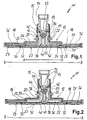
- a shower 11 according to the invention is shown.
- the showerhead 11 consists of a housing shell 12, which sits on a base 13 and is guided over this. By means of a lock nut 15, the shower head 11 is connected to a water connection 14 in a known ball head design.
- the water connection 14 sits, for example, on a ceiling.
- the housing shell 12 has approximately the shape of a tubular extension 17, which merges into the flat extension 18 downwards.
- the base 13 is formed, which widens also with an extension 24 downwards.
- the extension 24 of the base 13 has at the outer end a circumferential and downward annular shoulder 25. Its exact shape can be seen from Fig. 2. Down to goes the annular shoulder 25 in a narrow V-like profile over. In the position of FIG. 1, this serves the sealing effect. This will be discussed in more detail below.
- the showerhead 11 has a front side 27, which is connected to the housing shell 12 in the outside area.
- the front face 27 carries at its back the inserted jet disk 29.
- the jet disk 29 is made in a known manner from an elastomer and has molded nozzles for the formation of the outlet openings 30. From Fig. 1 and in particular Fig. 2 it can be seen that the back 31 of the jet disk 29 is substantially planar. Only the circumferential sealing lip 32 is integrally formed on the back 31. It can rest on the inside of the annular shoulder 25, as can be seen from Fig. 1.
- a water inlet 33 extends through the water connection 14 into the shower 11. From the ball head of the water connection 14 occurs the water through the openings 34, which are distributed around a central axis, in the upper part of the distribution chamber 36, which is located within the tube insert 17. As can be seen from Fig. 1, the water can reach due to the sealing concern of the expansion 24 with the adjacent annular shoulder 25 on the back 31 of the jet disk 29 lying only in this area outlet openings 30. Other river possibilities do not exist for the water. In particular, the outer area, ie area B without area A, is shut off.
- the distribution chamber 36 is fully open and now comprises the area of the openings 34 of the water inlet 33 over the entire surface of the back of the jet disk 29. Thus, the water can escape through all the outlet openings 30 of the jet disk 29.
- the shutter 42 is disengaged from the upper opening of the air channel 38.
- the air supply 40 from the front of the jet disk 29 and the front side 27 of the shower 11 in the shower or in the distribution chamber 36 into free.
- the air exiting from the upper opening of the air duct 38 passes approximately transversely to the water which shoots down through the openings 34 into the distribution chamber 36. Due to the Venturi effect, the incoming water entrains the air. At the same time, some mixing of water and air already begins.
- Verwirbelungsabsatz 46 which is integrally formed in the lower region of the outer side of the air channel 38.
- Verwirbelungsabsatzes 46 is here from the top impinging water to the side, ie in the lateral extent of the distribution chamber 36 into, deflected. But it is also achieved turbulence or mixing of the water-air mixture.
- the Verwirbelungsabsatz is formed stepwise with multiple stages. The course of the steps can correspond to the bevel.
- the course of the extension 24 of the base 13 is corresponding to the course of the extension 18 of the housing shell 12.
- the gradation in the extension 18 serves to provide room for the extension 24 entering this step. Furthermore, it limits the outer annular region of the distribution chamber 36 such that the water supply to all outlet openings 30 in the position of FIG. 2, ie when water is supplied to the entire area of the jet disk 29, is approximately equal.
- Fig. 2 it can be seen that it is possible under some circumstances, in addition to a more or less stage switching between the first area A and second area B and correspondingly between unventilated and ventilated, at least one of the function also adjustable to design. In particular, this offers the ventilation device.
- the shape of the lower part of the closure 42 and the corresponding opening in the upper part of the air duct 38 may be formed such that over the entire displacement of the relative movement between housing shell 12 and base 13, a continuous opening of the air supply 40 via the air paths 44 takes place. This can be even greater than when opening the distribution chamber 36.
- FIG. 3 shows a shower similar to the embodiment of FIGS. 1 and 2, but without a changeover device.
- an insert plate 50 is arranged, which with the outlet openings 30 of the jet disk 29 has corresponding openings 51.
- the insert plate is made of a harder plastic than the jet disk 29. It has, inter alia, the task of fixing the elastomer jet disk 29 on the front side 27 and on the bottom 52 of the housing. This is to prevent the beam angle of the individual jet outlet nipples from changing during operation or during assembly.
- the insert plate 50 On its rear side, the insert plate 50 contains individual ribs 53, which serve to subdivide the space between the jet disk and the rear wall 52 of the housing. This subdivision is intended to guide and direct the individual aerated jets within the housing.
- FIG. 4 shows another embodiment of a shower, which is particularly simple this time.
- the shower enclosure contains a rear wall 52 and a very simple jet disk 54, between which a very flat disc-like distribution chamber 55 is formed.
- the sealing takes place in the edge region by a groove 56 in the back 52 existing seal which rests on the back 56 of the jet disk 54, see Figure 6.
- the jet disk 54 is formed here from a total of a relatively hard plastic, so that the direction and Do not change the shape of the jet outlet openings 57.
- FIG. 5 represents an enlargement of the housing of FIG. 4, the jet outlet openings 57 are arranged obliquely and conically.
- the connection of the housing of the shower of Figure 3 and 4 with the water supply corresponds to that of Figure 1, so that these details will not be explained in detail.
- the water passing through the inlet now strikes a perforated disk 60 arranged transversely to the flow direction of the water, see the enlarged illustration in FIG. 7.
- the perforated disk 60 is circular and flat and has an edge flange running in the direction of flow 61 on.
- the opening 62 of the inlet has a significantly smaller diameter than the perforated disc 60.
- the arranged in the perforated disc 60 circular holes 63 are arranged along the circumference. The water must therefore first be deflected out of the opening 62 before it reaches the openings 63.
- FIG. 7 shows the embodiment of FIG. 3 on an enlarged scale.
- the inner end of the ventilation hub 64 is formed by a flat end surface 65. This is located at a small distance in front of or behind the perforated disc 60.
- the air sucked in through the central opening 40 of the ventilation hub 64 is directed as a very narrow, flat stream onto the already separated water jets. Due to the rapid flow of the water jets downstream of the holes 63 creates a Venturi effect, which sucks the air flow there.
- the aerated jets then pass along the cylindrical outer surface 66 of the breather hub 64 to the root 67 of the hub, where the outer side widens conically at an angle of, for example, about 45 degrees.
- This conical extension 67 rests on the insert plate 50, on which the water then flows radially in a plane further outward.
- the angle of the deflection 68 may be between 10 and 80 degrees. It is also conceivable a gradual curved Crossing.
- This deflection device serves to divert the aerated water jets produced radially outward into the distribution chamber arranged behind the jet disk.
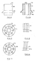
- Figure 8 shows very schematically the plan view of the perforated disc 60 with eight holes 63.
- the number of holes 63 is larger in order to produce the largest possible number of water jets. All holes 63 lie on a circle near the outer periphery of the perforated disc 60.
- FIG. 9 shows the ventilation hub 64 of FIG. 7 in a side view. It can clearly be seen that the deflection surface 68 extends over the entire circumference.
- the lateral surface 66 is smooth in the embodiment shown here.
- the face 65 also.
- FIGS. 10 to 12 show an embodiment of a ventilation hub 164 which is modified with respect to the ventilation hub 64.
- a plurality of radially extending channels 70 are formed in the end face 165 and lead from the interior 40 of the hub 164 to the outside.
- axial channels 71 are provided, which are formed by grooves.
- Each radial channel 70 merges into an axial channel 71.
- further channels 72 are formed in the extension of the channels 70 and 71, whose depth, see Figure 10, decreases to the end of the deflection 68. In this way, at the end face 165 of the ventilation hub 164 is ensured that individual air jets occur, which then hit the water jets formed there through the holes 63.
- Figures 13 and 14 show the corresponding representations in another ventilation hub, in which the channels 172 in the deflection 168 bent or curved run. This gives the aerated jets an oblique direction, which they maintain when leaving the ventilation hub. In this way, a turbulence of the ventilated jets is achieved within the distribution chamber of the showerhead.
- the channels 171 are not rectilinear parallel to the axis, as in the embodiment of Figure 12, but obliquely to the axis. So they run in the manner of a steep thread. This initiates the generation of a twist of the ventilated jets earlier.
- the ventilation hub 164 of FIG. 10 may be arranged, for example, such that the areas in the plane of the end face 165 between the channels 70 touch the perforated plate 60 on its underside. Then completely separate air jets are generated. However, it may also remain a certain distance, so that paths of preferred flow at the location of the channels 70 are generated.
- the baffles on the basis of the ventilation hubs can also be continued in the distribution chamber.
- the jet outlet openings can be arranged in a straight line extension of the projection of the channels 72, 172. Not all channels 72 and 172 need to have the same curvature or the same direction. It can be ensured that ventilated water jets, which are to be directed farther out in the distribution chamber, leave the foot of the ventilation hub in a more straight line, while the rays intended for the closer jet outlet openings are provided with greater turbulence.
- FIGS. 3 to 14 show, for reasons of simplified illustration, no switching device for switching over between different areas of the beam exit surface. They also show no means for switching on and off the ventilation device.
- the measures for the production and maintenance of individual ventilated jets are of course also possible and useful in showers in which such switching devices are available.
- the invention expressly proposes this.
Abstract
Description
Die Erfindung betrifft eine Brause mit einem Gehäuse und einer Strahlaustrittsfläche aus dem Gehäuse. Die Strahlaustrittsfläche weist eine Vielzahl von Austrittsöffnungen auf. Derartige Brausen sind in vielseitiger Form bereits seit langem bekannt und weisen an sich zahlreiche Funktionsmöglichkeiten auf.The invention relates to a shower with a housing and a beam exit surface of the housing. The jet exit surface has a plurality of outlet openings. Such showers have long been known in many forms and have many functional possibilities.
Der Erfindung liegt die Aufgabe zugrunde, eine eingangs genannte Brause mit Funktionsmöglichkeiten zu schaffen, welche im Stand der Technik noch nicht bekannt sind und insbesondere eine vorteilhafte Benutzung ermöglichen.The invention has for its object to provide an aforementioned shower with functional capabilities that are not yet known in the art and in particular allow a beneficial use.
Es ist bereits ein Brausekopf mit einer Belüftungseinrichtung bekannt (DE 10103649). Hinter der Strahlscheibe sind zwei Kammern gebildet, von denen die äußere mit unbelüftetem Wasser und die innere mit belüftetem Wasser versorgt wird. Die äußere Kammer kann abgeschaltet werden. Das Wasser strömt aus beiden Kammern ungeleitet durch die Strahlaustrittsöffnungen in der Strahlscheibe ins Freie.It is already a shower head with a ventilation device known (DE 10103649). Behind the jet disk are formed two chambers, of which the outside is supplied with unaerated water and the inside with aerated water. The outer chamber can be switched off. The water flows from both chambers uncontrolled through the jet outlet openings in the jet disk to the outside.
Weiterhin ist ein Brausekopf bekannt, der ebenfalls zwei Kammern hinter der Strahlscheibe aufweist, nämlich eine innere Kammer und eine äußere Kammer. Das Wasser in der inneren Kammer wird durch Öffnungen zwischen den Brausekopf und seiner Befestigung belüftet. Das belüftete Wasser tritt durch Öffnungen in der Trennwand in die äußere Kammer ein. Das ungerichtete Wasser strömt belüftet aus allen Strahlaustrittsöffnungen aus (DE 3825537).Furthermore, a shower head is known, which also has two chambers behind the jet disk, namely an inner chamber and an outer chamber. The water in the inner chamber is vented through openings between the shower head and its attachment. The aerated water enters the outer chamber through openings in the dividing wall. The non-directional water flows ventilated from all the beam outlet openings (DE 3825537).
Weiterhin bekannt ist eine gattungsgemäße Handbrause (US 4135670), bei der in Strömungsrichtung vor der die Strahlaustrittsöffnungen aufweisenden Strahlscheibe eine innere Scheibe angeordnet ist, deren Löcher gegenüber den Strahlaustrittsöffnungen ausgerichtet sind. In dem Raum zwischen den beiden Scheiben wird Luft durch Öffnungen angesaugt. Aus den Strahlaustrittsöffnungen treten daher belüftete Strahlen aus.Also known is a generic hand shower (US 4135670), in which in the flow direction in front of the jet outlet openings having jet disk, an inner disc is arranged, whose holes are aligned with respect to the jet outlet openings. Air is sucked through openings in the space between the two panes. Ventilated jets therefore escape from the jet outlet openings.
Gelöst wird diese Aufgabe durch eine Brause mit den Merkmalen des Patentanspruchs 1. Vorteilhafte sowie bevorzugte Ausgestaltungen der Erfindung sind Gegenstand der weiteren Ansprüche und werden im folgenden näher erläutert. Der Wortlaut der Ansprüche und der Zusammenfassung wird hiermit durch ausdrückliche Bezugnahme zum Inhalt der Beschreibung gemacht.This object is achieved by a shower with the features of claim 1. Advantageous and preferred embodiments of the invention are the subject of further claims and are explained in more detail below. The terms of the claims and abstract are hereby incorporated by express reference into the content of the specification.
Die Brause enthält ein Gehäuse, das zu der Benutzerseite hin durch eine Strahlscheibe abgeschlossen wird. Diese Strahlscheibe enthält eine Vielzahl von Strahlaustrittsöffnungen, die durch bestimmte Anordnungen speziell gestaltet sein können. Insbesondere enthält die Brause ein flaches großes Gehäuse. Die Belüftungseinrichtung kann beispielsweise so ausgebildet sein, dass sie die Luft durch die Strahlaustrittsscheibe in das Gehäuse einführt, beispielsweise direkt in der Mitte in der vorzugsweise ebenen Strahlscheibe.The shower contains a housing which is closed off to the user side by a jet disk. This jet disc contains a plurality of jet outlets, which may be specially designed by certain arrangements. In particular, the shower contains a flat large housing. By way of example, the ventilation device can be designed such that it introduces the air through the jet exit disk into the housing, for example directly in the middle in the preferably flat jet disk.
Um eine besonders sinnvolle Verteilung des belüfteten Wassers innerhalb des Gehäuses und damit eine besonders sinnvolle Verteilung der belüfteten Strahlen außerhalb des Gehäuses zu erreichen, kann die Brause erfindungsgemäß in Weiterbildung ein Strahlbildungsmittel zum Bilden mehrerer einzelner Wasserstrahlen schon innerhalb des Gehäuses enthalten. Die einzelnen Wasserstrahlen werden also nicht erst beim Verlassen der Brause gebildet. Auf diese Weise ist es möglich, innerhalb des Gehäuses schon bestimmte Vorgänge mit den Wasserstrahlen durchzuführen.In order to achieve a particularly expedient distribution of the aerated water within the housing and thus a particularly useful distribution of the ventilated jets outside the housing, the showerhead according to the invention may further comprise a jet forming means for forming a plurality of individual water jets within the housing. The individual water jets are therefore not formed when leaving the shower. In this way, it is possible to perform certain processes within the housing with the water jets.
Die Belüftungseinrichtung kann in Weiterbildung der Erfindung derart ausgebildet sein, dass sie das Wasser vor dem Strahlbildungsmittel belüftet. Dann dient das Strahlbildungsmittel dazu, aus einem belüfteten Strahl einzelne belüftete Strahlen zu bilden, die dann innerhalb des Brausegehäuses verteilt werden, beispielsweise auf eine Fläche, die einen gegenüber dem Wassereinlass großen Durchmesser aufweist, beispielsweise einen im Bereich von 10 bis 20-Mal größeren Durchmesser.The ventilation device may be formed in a development of the invention such that it aerates the water in front of the beam forming agent. Then, the jet-forming means serves to form a ventilated jet of individual aerated jets, which are then distributed within the showerhead, for example, to a surface having a large diameter relative to the water inlet, for example, a diameter of 10 to 20 times larger ,
Es ist aber ebenfalls möglich und wird von der Erfindung bevorzugt, dass das Strahlbildungsmittel und/oder die Belüftungseinrichtung derart ausgebildet ist, dass die einzelnen schon gebildeten Strahlen gemeinsamen und/oder getrennt belüftet werden. Dadurch wird es möglich, bei der Bildung der Wasserstrahlen die spätere Belüftung noch nicht berücksichtigen zu müssen.However, it is also possible and preferred by the invention that the beam-forming means and / or the ventilation device is designed such that the individual beams already formed are ventilated jointly and / or separately. This makes it possible to not have to consider the subsequent ventilation in the formation of water jets.
In nochmaliger Weiterbildung der Erfindung kann die Brause Leitmittel aufweisen, um die belüfteten Wasserstrahlen zu den Strahlaustrittsöffnungen der gesamten Strahlscheibe zu leiten, vorzugsweise gleichmäßig, je nach Wunsch aber auch ungleichmäßig.In a further development of the invention, the shower can have guiding means to guide the aerated water jets to the jet outlet openings of the entire jet disk, preferably evenly, but also unevenly as desired.
Die Leitmittel können dabei an unterschiedlichsten Stellen der Brause angeordnet sein, beispielsweise in der Verteilerkammer, die direkt hinter der Strahlscheibe ausgebildet ist. Die Leitmittel können aber auch dort angeordnet sein, wo die gebildeten Strahlen belüftet oder die belüfteten Strahlen gebildet werden.The guide means can be arranged at different points of the shower, for example in the distribution chamber, which is formed directly behind the jet disk. However, the conducting means can also be arranged where the formed rays are aerated or the aerated rays are formed.
Beispielsweise können in Weiterbildung die Leitmittel und/oder die Belüftungseinrichtung derart ausgebildet sein, dass sie eine Verwirbelung der belüfteten Strahlen erzeugen. Diese verlegt wird gelungen ist unter anderem dazu geeignet, innerhalb des Brausegehäuses die Aufenthaltsdauer der Strahlen zu vergrößern, um auf diese Weise einen längeren und/oder intensiveren Kontakt mit ihm dem Brausegehäuse vorhandenen Einrichtungen zu erreichen.For example, in a further development, the conducting means and / or the ventilating device may be designed such that they produce a turbulence of the ventilated jets. This laid is successful, inter alia, is suitable to increase the residence time of the beams within the shower enclosure, in order to achieve in this way a longer and / or more intensive contact with him the shower enclosure existing facilities.
Die Belüftungseinrichtung kann in Weiterbildung der Erfindung so ausgebildet sein, dass sie eine Luftströmung erzeugt, die senkrecht auf die Wasserströmung trifft, wobei sie, wie bereits erwähnt, auf schon gebildete einzelne Wasserstrahlen treffen kann.The ventilation device may be formed in a further development of the invention so that it generates an air flow that meets perpendicular to the flow of water, where they, as already mentioned, can meet already formed individual water jets.
Es ist aber ebenfalls möglich und liegt im Rahmen der Findung, die Belüftungseinrichtung derart auszubilden, dass sie schon einzelne Luftstrahlen oder Luftströmungen erzeugt, die dann schon getrennt auf die Wasserströmung treffen.However, it is also possible and is within the scope of the invention to design the ventilation device such that it already generates individual air jets or air flows, which then already meet the water flow separately.
Insbesondere kann vorgesehen sein, dass jeder Luftstrahl einem Wasserstrahl zugeordnet ist, auf den er trifft. Es kann eine vollständige oder nur teilweise Trennung von Luftströmungen und Wasserströmungen in dem Gehäuse durchgeführt werden. Es ist dadurch möglich, die einzelnen Wasserstrahlen unterschiedlich stark oder auch an einer unterschiedlichen Stelle zu belüften.In particular, it can be provided that each air jet is assigned to a water jet, which it encounters. Complete or partial separation of air currents and water flows in the housing may be performed. It is thereby possible to ventilate the individual water jets different degrees or at a different location.
Zur Erzeugung der einzelnen Wasserstrahlen kann das Strahlbildungsmittel beispielsweise eine Lochscheibe aufweisen, die quer zur Wasserströmung angeordnet ist. Durch jedes Loch wird dann ein Wasserstrahl erzeugt. Diese Wasserstrahlen können, wie bereits erwähnt, entweder vollständig getrennt sein, oder auch nur teilweise getrennt, so dass sich innerhalb eines gemeinsamen Wasservolumens unterschiedliche einzelne Strömungsfäden herausbilden.For generating the individual water jets, the jet-forming means may comprise, for example, a perforated disc which is arranged transversely to the water flow. Through each hole then a jet of water is generated. These water jets can, as already mentioned, either be completely separated or else only partially separated so that different individual flow threads develop within a common water volume.
Die Belüftungseinrichtung kann eine zentrale Hülse oder Nabe aufweisen, durch deren Inneres die Luft von außen in das Innere des Gehäuses gelangt. An dem inneren Ende kann die Nabe beispielsweise eine glatte Stirnfläche aufweisen, die mit einer entsprechenden Gegenfläche einen flachen Ringraum bildet, durch den die Luftströmung auf das Wasser gerichtet wird. Es ist aber ebenfalls möglich und liegt im Rahmen der Erfindung, dass dieses Stirnende radiale Luftführungen, beispielsweise Nuten, aufweist, die zu einer Vereinzelung der Luftströmung führen.The ventilation device may comprise a central sleeve or hub, through whose interior the air passes from the outside into the interior of the housing. At the inner end, the hub may, for example, have a smooth end surface, which forms with a corresponding mating surface a flat annular space through which the air flow is directed to the water. But it is also possible and is within the scope of the invention that this front end radial air ducts, such as grooves, which lead to a separation of the air flow.
Das Ende der radialen Luftführungen, beispielsweise der Nuten oder der Kanäle, ist gegenüber den Öffnungen der Lochscheibe ausgerichtet. Die Ausrichtung kann beispielsweise so sein, dass die Mittellinie der Nuten auf die Mitte der Öffnungen zielt. Es ist aber ebenfalls möglich, dass eine tangentiale Ausrichtung gegeben ist, so dass die Mittellinie der Nuten außermittig bis tangential zu den Öffnungen der Lochscheibe verläuft.The end of the radial air ducts, such as the grooves or the channels, is aligned with the openings of the perforated disc. For example, the orientation may be such that the centerline of the grooves is toward the center of the apertures. However, it is also possible that a tangential orientation is given, so that the center line of the grooves extends off-center to tangentially to the openings of the perforated disc.
Die Luftführungen können exakt radial oder leicht schräg verlaufen.The air ducts can run exactly radially or slightly obliquely.
Die Nabe, an deren innerem Ende die Luft im wesentlichen radial in einer Ebene zur Längsachse ausströmt, kann an ihrer äußeren Mantelfläche, die in einer Zylinderfläche liegt, auch Führungen für die belüfteten Strahlen enthalten. Bei diesen Führungen kann es sich um die Nuten handeln, die gegenüber den Löchern in der Lochscheibe ausgerichtet sind. Diese Führungen dienen dazu, die belüfteten Strahlen bei ihrem weiteren Weg innerhalb des Brausegehäuses vereinzelt zu lassen, das heißt ihre Wiedervereinigung zu verzögern oder zu behindern.The hub, at the inner end of which the air flows substantially radially in a plane to the longitudinal axis, may also contain guides for the aerated jets on its outer circumferential surface, which lies in a cylindrical surface. These guides may be the grooves aligned with the holes in the perforated disc are. These guides serve to separate the aerated jets as they travel further within the showerhead, that is, to retard or hinder their reunification.
Die Nuten können in erster Linie in axialer Richtung verlaufen, sie können aber auch leicht schräg verlaufen, beispielsweise nach Art eines Steilgewindes.The grooves may extend primarily in the axial direction, but they may also be slightly oblique, for example in the manner of a coarse thread.
Am Fuß der Nabe, das heißt an der Stelle, wo die Wasserströmung radial nach außen in das Innere des Brausegehäuses umgeleitet werden soll, kann eine Umlenkung durch eine entsprechende kegelförmige Gestaltung der Außenseite der Nabe erfolgen. Diese Umlenkung kann auch allmählich geschehen, beispielsweise dadurch, dass die Außenseite der Nabe in einer geschwungenen Form in eine radiale Ebene übergeht. Diese geschwungene Form oder das allmähliche Übergehen oder die Umlenkung kann auch unabhängig von dem Vorhandensein von axialen Wasserführungen geschehen.At the foot of the hub, that is, at the point where the water flow is to be redirected radially outward into the interior of the shower housing, a deflection by a corresponding conical design of the outside of the hub can take place. This deflection may also be gradual, for example, by the outer side of the hub transitioning into a radial plane in a curved shape. This curved shape or the gradual transition or the deflection can also be done independently of the presence of axial water ducts.
Die Umlenkmittel können auch, je nach dem gewünschten Zweck, einzelne Kanäle aufweisen, die dann geradlinig linear, schräg oder gekrümmt verlaufen können.The deflection means may also, depending on the desired purpose, have individual channels, which may then be straight linear, oblique or curved.
Innerhalb des Gehäuses der Brause, das heißt hinter der Strahlscheibe, können Leitmittel angeordnet sein, die mit der Richtung der Umlenkmittel ausgerichtet sein können. Hiermit soll eine gute Verteilung der belüfteten Wasserstrahlen über die gesamte Fläche der Strahlscheibe erreicht werden. Die Leitmittel können beispielsweise an der Rückseite des Gehäuses oder auch an einer Einlage in dem Gehäuse vorhanden sein.Within the housing of the shower, that is behind the jet disk, guide means may be arranged, which may be aligned with the direction of the deflection means. This is to achieve a good distribution of the aerated water jets over the entire surface of the jet disk. The guide means may be present, for example, on the back of the housing or on an insert in the housing.
In Weiterbildung kann eine Brause zusätzlich zu einem Gehäuse und einer Strahlaustrittsfläche mit Austrittsöffnungen und einer Unterteilung in mindestens zwei Bereiche eine Umstelleinrichtung aufweisen. Mit dieser Umstelleinrichtung kann die Wasserzufuhr zwischen einem ersten Bereich und einem zweiten Bereich umgestellt werden. Des weiteren ist ein Wasserzutritt in die Brause vorgesehen, der für die Wasserzufuhr in die Brause sorgt. Eine Luftzufuhreinrichtung ist vorgesehen zur Belüftung der aus der Brause austretenden Wasserstrahlen. Mittels der Luftzufuhreinrichtung wird die Wasserzufuhr belüftet, und zwar zwischen Wasserzutritt und Strahlaustrittsfläche. Die Luftzufuhreinrichtung ist aktivierbar und deaktivierbar, kann also umgeschaltet werden. Die Umstelleinrichtung und die Luftzufuhreinrichtung sind erfindungsgemäß derart miteinander gekoppelt, dass beim Betätigen der Umstelleinrichtung die Luftzufuhr von aktiviert auf deaktiviert oder von deaktiviert auf aktiviert umgestellt wird. Somit wechselt die Luftzufuhreinrichtung ihren Aktivierungszustand, wenn von dem ersten auf den zweiten Bereich umgestellt wird. Mit anderen Worten ist erfindungsgemäß bei Betätigen der Umstelleinrichtung eine Doppelfunktion gegeben. Somit ist es hier auch klar, dass die Betätigungsrichtung auch anders herum sein könnte, also beim Aktivieren oder Deaktivieren der Luftzufuhreinrichtung ein Wechsel von einem Bereich auf den anderen.In a further development, a showerhead in addition to a housing and a beam exit surface with outlet openings and a subdivision have in at least two areas a switching device. With this changeover device, the water supply can be switched between a first area and a second area. Furthermore, a water access is provided in the shower, which ensures the supply of water into the shower. An air supply device is provided for ventilation of the water jets emerging from the shower. By means of the air supply device, the water supply is ventilated, namely between water inlet and jet exit surface. The air supply device can be activated and deactivated, so it can be switched. The changeover device and the air supply device according to the invention are coupled to one another in such a way that upon actuation of the changeover device the air supply is switched from activated to deactivated or from deactivated to activated. Thus, the air supply means changes its activation state when switching from the first to the second area. In other words, according to the invention, a double function is given when the changeover device is actuated. Thus, it is also clear here that the direction of actuation could also be the other way round, ie when activating or deactivating the air supply device, a change from one area to the other.
Auf diese Weise ergibt sich eine vorteilhafte Doppelfunktion. Mit einer einzigen Betätigung werden zwei Funktionen ausgelöst. Vor allem ist es möglich, die Funktion der Luftzufuhreinrichtung bezüglich aktiviert oder deaktiviert mit der Auswahl der Bereiche zusammenzulegen bzw. davon abhängig zu machen.
In weiterer Ausbildung der Erfindung ist es möglich, den ersten Bereich als Teilbereich der Strahlaustrittsfläche auszubilden, wobei er beispielsweise ein zentraler Bereich sein kann. Hier ist es möglich, als zweiten Bereich die gesamte Strahlaustrittsfläche vorzusehen. Beispielsweise kann die Luftzufuhr dann aktiviert sein, wenn die Umstelleinrichtung auf den zweiten Bereich bzw. auf die gesamte Stahlaustrittsfläche gestellt ist. Dies weist den Vorteil auf, dass durch die Luftzufuhr bzw. die Belüftung der Wasserstrahlen ein voluminöser erscheinender Wasseraustritt geschaffen werden kann, der gerade bei der vergrößerten Anzahl von Austrittsöffnungen im Falle eines größeren Bereichs von Vorteil ist.In this way, there is an advantageous dual function. With a single operation, two functions are triggered. Above all, it is possible to combine the function of the air supply device with respect to activated or deactivated with the selection of the areas or to make it dependent.
In a further embodiment of the invention, it is possible to form the first region as a partial region of the beam exit surface, wherein it may be, for example, a central region. Here it is possible to provide the second beam area as the second area. For example, the air supply can be activated when the changeover device is placed on the second region or on the entire steel exit surface. This has the advantage that by the air supply or ventilation the water jets, a voluminous appearing water outlet can be created, which is just in the increased number of outlet openings in the case of a larger area of advantage.
Die Umstelleinrichtung ist vorteilhaft von Hand betätigbar. Dazu kann entweder ein Knopf oder Schieber oder ähnliches eingedrückt werden. Vorteilhaft kann ein gesamter und insbesondere größerer Gehäuseteil gegenüber einem anderen Gehäuseteil oder dem Rest des Gehäuses bewegt werden.The switching device is advantageous operable by hand. For this purpose, either a button or slider or the like can be pressed. Advantageously, an entire and in particular larger housing part can be moved relative to another housing part or the rest of the housing.
Die beiden Bereiche bzw. alle Bereiche können über eine Verteilerkammer mit dem Wasserzutritt verbunden sein für die Wasserzufuhr. Die Verteilerkammer kann sich vorteilhaft über die Fläche aller Bereiche bzw. die Rückseite der Strahlaustrittsfläche erstrecken. So ist eine gute Wasserzufuhr für alle Bereiche und alle Strahlaustrittsöffnungen der Strahlaustrittsfläche gewährleistet. Die Umstelleinrichtung kann derart ausgebildet sein, dass sie in der Verteilerkammer angeordnet ist und wirkt. Sie kann bei der Einstellung auf den ersten Bereich die Verteilerkammer auf die dem ersten Bereich entsprechende Fläche begrenzen. Beim Umstellen auf einen anderen Bereich oder den zweiten Bereich wird die Begrenzung der Verteilerkammer der Fläche dieses weiteren Bereichs angepasst. Wird auf die gesamte Strahlaustrittsfläche umgestellt, so kann die Begrenzung der Verteilerkammer aufgehoben werden, so dass sie sich über die gesamte Strahlaustrittsfläche erstreckt.The two areas or all areas can be connected via a distribution chamber with the water inlet for the water supply. The distribution chamber can advantageously extend over the surface of all regions or the rear side of the jet exit surface. This ensures a good water supply for all areas and all the jet outlet openings of the jet outlet area. The changeover device can be designed such that it is arranged in the distribution chamber and acts. When setting to the first area, it can limit the distribution chamber to the area corresponding to the first area. When switching to another area or the second area, the boundary of the distribution chamber is adapted to the area of this wider area. If the entire beam exit surface is changed over, the boundary of the distribution chamber can be removed, so that it extends over the entire beam exit surface.
Die Umstelleinrichtung kann einen Verschluss aufweisen, welcher besonders bevorzugt zur Begrenzung der Verteilerkammer ausgebildet sein kann. Eine Begrenzung der Verteilerkammer ist leicht dadurch möglich, dass der Verschluss an die Rückseite der Strahlaustrittsfläche anlegbar ist. Vorteilhaft ist diese Anlage dichtend. Besonders vorteilhaft erfolgt die Begrenzung der Verteilerkammer durch eine Wandung als Verschluss. Der Bereich innerhalb dieser Wandung bildet vorteilhaft den Teil der Verteilerkammer, der dem gewählten Bereich der Strahlaustrittsfläche entspricht.The changeover device may have a closure, which may be particularly preferably designed to limit the distribution chamber. A limitation of the distribution chamber is easily possible because the closure can be applied to the back of the beam exit surface. Advantageously, this system is sealed. Particularly advantageous is the limitation of the distribution chamber by a wall as a closure. The area within this wall advantageously forms the Part of the distribution chamber, which corresponds to the selected area of the beam exit surface.
Zur Verbesserung der Dichtheit der Anlage kann eine ausgebildete Dichtung vorgesehen sein. Hierfür eignet sich beispielsweise eine Lippendichtung. Sie kann eine Anlagerichtung an einen Dichtungssitz aufweisen, welche in Richtung des Wasserdrucks in der begrenzten Verteilerkammer verläuft. So trägt ein entstehender Wasserdruck zusätzlich zur Dichtwirkung bei.To improve the tightness of the system, a trained seal may be provided. For this purpose, for example, a lip seal is suitable. It may have an abutment direction on a seal seat which extends in the direction of the water pressure in the limited distribution chamber. Thus, a resulting water pressure in addition to the sealing effect.
Eine Möglichkeit zur Ausführung einer Strahlaustrittsfläche besteht darin, ein elastisches Material zu wählen. Dies ist beispielsweise ein Elastomer, welches gummiartig sein kann. An eine solche Strahlscheibe können rückseitig eine Wandung oder ein Verschluss angelegt werden zur Erzielung einer Dichtwirkung. Eine zuvor angesprochene Dichtung kann vorteilhaft an der Rückseite der Strahlscheibe in abstehender Form angeformt werden. So kann man sich eine separate Dichtung sparen.One way to perform a beam exit surface is to choose an elastic material. This is, for example, an elastomer which may be rubbery. At such a jet disk back wall or a closure can be applied to achieve a sealing effect. A previously mentioned seal can advantageously be integrally formed on the back of the jet disk in protruding form. So you can save a separate seal.
Eine Wasserzufuhr erfolgt vorteilhaft zentral in die Brause, jedenfalls im Bereich kurz vor der Verteilerkammer. Somit ist eine möglichst gleichmäßige Verteilung über die Strahlaustrittsfläche hinweg möglich. Ebenso ist eine zentrale Luftzufuhreinrichtung zur Brause bzw. zur Strahlaustrittsfläche von Vorteil. Vorteilhaft erfolgt eine Wasserzufuhr von der Rückseite der Strahlaustrittsfläche bzw. der Brause. Eine Luftzufuhreinrichtung kann durch eine zentrale Öffnung in der Strahlaustrittsfläche verlaufen, also von vorne in das Gehäuse der Brause hinein.A water supply is advantageously carried out centrally in the shower, at least in the area just before the distribution chamber. Thus, the most uniform possible distribution over the beam exit surface is possible. Likewise, a central air supply to the shower or to the jet exit surface of advantage. Advantageously, a water supply from the back of the jet outlet surface or the shower. An air supply device can run through a central opening in the jet exit surface, ie from the front into the housing of the shower.
Für die Luftzufuhr kann ein Kanal vorgesehen sein, der nicht nur durch die Strahlaustrittsfläche verlaufen kann, sondern sogar mit ihr verbunden sein kann oder in ihrem Bereich befestigt ist. Des weiteren ist es möglich, die Umstelleinrichtung mit dem Wasserzutritt zu verbinden bzw. daran zu befestigen. Zum Umstellen und Aktivieren der Brause kann bei einer Ausbildung der Erfindung die Strahlaustrittsfläche gegenüber dem Wasserzutritt bewegt werden. Dabei kann dann ein Schließer an dem Wasserzutritt den Kanal für die Luftzufuhr schließen oder öffnen. Gleichzeitig würde beispielsweise eine Wandung der Umstelleinrichtung die Verteilerkammer begrenzen.For the air supply, a channel can be provided, which can not only pass through the jet exit surface, but can even be connected to it or fixed in its area. Furthermore, it is possible to connect the changeover with the access of water or to attach it. To change and activate the shower can at an embodiment of the invention, the jet exit surface are moved relative to the water inlet. In this case, a closer to the water inlet can close or open the channel for the air supply. At the same time, for example, a wall of the changeover device would limit the distribution chamber.
Zwar kann, wie zuvor ausgeführt, die Luftzufuhr durch die Vorderseite der Brause, und zwar durch die Strahlaustrittsfläche hindurch, verlaufen. Allerdings ist es von Vorteil, wenn die Luft aus dem Kanal der Luftzufuhr mit einer Richtung quer zur Wasserzufuhr oder des Wasserzutritts austritt. Unter Nutzung des Venturi-Effekts wird Luft angesaugt und es findet eine Verwirbelung des Wassers mit der Luft statt. Des weiteren kann so die Luft in die Wasserzufuhr verteilt werden.Although, as stated above, the air supply through the front of the shower, through the beam exit surface pass through. However, it is advantageous if the air exits the duct of the air supply with a direction transverse to the water supply or the water inlet. Using the Venturi effect, air is sucked in and there is a turbulence of the water with the air. Furthermore, the air can be distributed in the water supply.
Die Wasserzufuhr kann bei einer Ausbildung der Erfindung eine Vielzahl von Öffnungen aufweisen, welche ringförmig um eine zentrale Achse verteilt sein können. Die Öffnungen sind dabei vorteilhaft längliche Löcher, unter anderem zur Beschleunigung der einzelnen Wasserstrahlen. Unmittelbar hinter den Öffnungen kann die Luft aus der Luftzufuhr hinzutreten, beispielsweise durch den vorgenannten Venturi-Effekt. So ist eine gute Vermischung von Luft und Wasser erreichbar.The water supply, in one embodiment of the invention, may have a plurality of openings which may be distributed annularly about a central axis. The openings are advantageously elongated holes, among other things, to accelerate the individual water jets. Immediately behind the openings, the air from the air supply can occur, for example by the aforementioned Venturi effect. So a good mixing of air and water is achievable.
Des weiteren ist es möglich, in Richtung des Wasserflusse hinter der Stelle des Lufteintritts Verwirbelungseinrichtungen vorzusehen. Auf diese Verwirbelungseinrichtungen, welche beispielsweise die Form mehrerer Stufen aufweisen können, trifft das Gemisch aus Wasser und mitgerissener Luft und wird noch stärker verwirbelt und vermischt. Derartige Verwirbelungseinrichtungen sind vorteilhaft um eine zentrale Achse des Brausengehäuses oder um einen Kanal für die Luftzufuhr verteilt. Beispielsweise können sie an die Außenseiten der Kanalwandungen angeformt sein. Dies bietet sich besonders dann an, wenn der Kanal für die Luftzufuhr rohrartig ausgebildet ist, wobei er an der Vorderseite der Brause befestigt sein kann.Furthermore, it is possible to provide turbulizers in the direction of the water flow behind the location of the air inlet. In this turbulence, which may for example have the form of several stages, the mixture of water and entrained air hits and is even more swirled and mixed. Such turbulizers are advantageously distributed around a central axis of the shower enclosure or around a duct for the supply of air. For example, they can be formed on the outer sides of the channel walls. This is especially useful when the channel for the Air supply is formed like a tube, where it may be attached to the front of the shower.
Zusätzlich zu Ihrer Verwirbelungsfunktionen können die Verwirbelungseinrichtungen dafür ausgebildet sein, die Wasserzufuhr über den gesamten Rückbereich der Strahlaustrittsfläche innerhalb der Verteilerkammer sicherzustellen bzw. die Wasserzufuhr umzulenken und zu verteilen. Vorteilhaft erfolgt eine annähernd gleichmäßige Verteilung der Wasserzufuhr in die Verteilerkammer hinein.In addition to their Verwirbelungsfunktionen the turbulators can be designed to ensure the supply of water over the entire rear portion of the jet exit surface within the distribution chamber or to redirect the water supply and distribute. Advantageously, an approximately uniform distribution of the water supply into the distribution chamber takes place.
Die von der Erfindung vorgeschlagene Brause kann insbesondere auch als Seitenbrause Verwendung finden. Durch die Zumischung von Luft erreichen die Wasserstrahlen eine größere Wurfweite, was bei einer vertikal angeordneten Strahlaustrittsfläche den Vorteil hat, dass die Wasserstrahlen einen in einem gewissen Abstand stehenden Körper auch großflächig und in der gewünschten Höhe treffen. Da die Luftansaugung von der Vorderseite her durch die Strahlaustrittsfläche geschieht, wird die Ausbildung und Anordnung einer Seitenbrause und ihre Montage gegenüber den bekannten ohne Luftbeimischung aus kommenden Seitenbrausen nicht kompliziert oder erschwert.The shower proposed by the invention can also be used as a side shower in particular. By adding air, the water jets reach a greater throwing distance, which has the advantage, in the case of a vertically arranged jet exit face, that the water jets strike a body standing at a certain distance over a large area and at the desired height. Since the air intake from the front side is done through the jet exit surface, the formation and arrangement of a side shower and its installation is not complicated or difficult compared to the known without adding air from coming overhead showers.
Diese und weitere Merkmale gehen außer aus den Ansprüchen auch aus der Beschreibung und den Zeichnungen hervor, wobei die einzelnen Merkmale jeweils für sich allein oder zu mehreren in Form von Unterkombinationen bei einer Ausführungsform der Erfindung und auf anderen Gebieten verwirklicht sein und vorteilhafte sowie für sich schutzfähige Ausführungen darstellen können, für die hier Schutz beansprucht wird.These and other features will become apparent from the claims but also from the description and drawings, wherein the individual features each alone or more in the form of sub-combinations in an embodiment of the invention and in other fields be realized and advantageous and protectable Represent embodiments for which protection is claimed here.
Ein Ausführungsbeispiel der Erfindung ist in den Zeichnungen dargestellt und wird im folgenden näher erläutert.
In den Zeichnungen zeigen:
- Figur 1
- einen Schnitt durch eine erfindungsgemäße Brause mit einem auf einen ersten Zentralbereich beschränkten Wasseraustritt und ohne Luftzufuhr und
- Figur 2
- die Brause aus Fig. 1 mit Luftzufuhr und Umstellen auf die gesamte Strahlaustrittsfläche.
- Figur 3
- eine der Figur 1 entsprechende Darstellung bei einer weiteren Ausführungsform;
- Figur 4
- einen der Figur 3 entsprechenden Schnitt durch eine nochmals weitere Ausführungsform;
- Figur 5
- in vergrößertem Maßstab einen Querschnitt durch die Strahlscheibe der Ausführungsform der Figur 4;
- Figur 6
- einen vergrößerten Querschnitt durch den Rand des Gehäuses der Ausführungsform nach Figur 4;
- Figur 7
- in vergrößertem Maßstab einen Schnitt durch den mittleren Teil der Ausführungsform der Figur 3;
- Figur 8
- eine Draufsicht auf die Lochscheibe der Ausführungsform nach Figur 7;
- Figur 9
- eine Seitenansicht der Belüftungsnabe bei der Ausführungsform nach Figur 3 und 7;
- Figur 10
- einen Axialschnitt durch eine gegenüber Figur 9 abgeänderte Belüftungsnabe;
Figur 11- die Ansicht der Belüftungsnabe der Figur 10 von oben;
Figur 12- eine Abwicklung der Seitenansicht der Belüftungsnabe der Figur 10
und 11; Figur 13- eine der Figur 11 entsprechende Darstellung bei einer geänderten Ausführungsform;
Figur 14- die Abwicklung der Seitenansicht der Ausführungsform nach Figur 13.
In the drawings show:
- FIG. 1
- a section through a shower according to the invention with a limited to a first central area water outlet and without air supply and
- FIG. 2
- the shower of Fig. 1 with air supply and switching to the entire beam exit surface.
- FIG. 3
- a representation corresponding to Figure 1 in a further embodiment;
- FIG. 4
- a section corresponding to Figure 3 through yet another embodiment;
- FIG. 5
- on an enlarged scale, a cross section through the jet disk of the embodiment of Figure 4;
- FIG. 6
- an enlarged cross section through the edge of the housing of the embodiment of Figure 4;
- FIG. 7
- on an enlarged scale, a section through the middle part of the embodiment of Figure 3;
- FIG. 8
- a plan view of the perforated disc of the embodiment of Figure 7;
- FIG. 9
- a side view of the ventilation hub in the embodiment of Figure 3 and 7;
- FIG. 10
- an axial section through a relative to Figure 9 modified ventilation hub;
- FIG. 11
- the view of the ventilation hub of Figure 10 from above;
- FIG. 12
- a development of the side view of the ventilation hub of Figure 10 and 11;
- FIG. 13
- an illustration corresponding to Figure 11 in a modified embodiment;
- FIG. 14
- the development of the side view of the embodiment of Figure 13.
In den Fig. 1 und 2 ist eine erfindungsgemäße Brause 11 dargestellt. Die Brause 11 besteht aus einem Gehäusemantel 12, welcher an einer Basis 13 sitzt bzw. über diese geführt ist. Mittels einer Verschlussmutter 15 ist die Brause 11 mit einem Wasseranschluss 14 in bekannter Kugelkopfausführung verbunden. Der Wasseranschluss 14 sitzt beispielsweise an einer Decke.In Figs. 1 and 2, a
Der Gehäusemantel 12 weist in etwa die Form eines Rohransatzes 17 auf, der nach unten hin in die flächige Ausweitung 18 übergeht. Auf ähnliche Art und Weise ist die Basis 13 ausgebildet, welche sich ebenfalls mit einer Ausweitung 24 nach unten hin verbreitert.The
Im oberen Teil der Basis 13 sind Gummiringe 20 eingesetzt. Des weiteren stehen Vorsprünge 22 ab. Mittels der Gummiringe 20 ist eine dichtende Verbindung zu dem Rohransatz 17 des Gehäusemantels 12 gegeben. Des weiteren weist der Rohransatz 17 Nuten 19 auf, die schräg verlaufen nach Art eines Gewindes. In diese Nuten greifen die Vorsprünge 22 ein. So verschiebt sich der Gehäusemantel 12 beim Drehen relativ zu der Basis 13, wie aus dem Vergleich zwischen Fig. 1 und Fig. 2 deutlich ist. Anstelle einer solchen gewindeähnlichen Ausführung könnte auch mittels kurzer Nuten und Vorsprüngen ein Drücken und somit Verschieben des Gehäusemantels 12 relativ zu der Basis 13 direkt entlang der Mittelachse erfolgen zum Verstellen.In the upper part of the base 13 rubber rings 20 are used. Furthermore,
Die Ausweitung 24 der Basis 13 weist am äußeren Ende einen umlaufenden und nach unten stehenden Ringabsatz 25 auf. Dessen genaue Form kann aus Fig. 2 ersehen werden. Nach unten zu geht der Ringabsatz 25 in ein schmales V-ähnliches Profil über. Bei der Stellung nach Fig. 1 dient dieses der Dichtwirkung. Darauf wird nachfolgend noch genauer eingegangen.The
Des weiteren weist die Brause 11 eine Vorderseite 27 auf, welche im Außenbereich mit dem Gehäusemantel 12 verbunden ist. Die Vorderseite 27 trägt an ihrer Rückseite die eingesetzte Strahlscheibe 29. Die Strahlscheibe 29 ist auf bekannte Art und Weise aus einem Elastomer hergestellt und weist angespritzte Düsen auf zur Bildung der Austrittsöffnungen 30. Aus Fig. 1 und insbesondere Fig. 2 ist zu erkennen, dass die Rückseite 31 der Strahlscheibe 29 im wesentlichen eben ist. Lediglich die rings umlaufende Dichtlippe 32 ist an der Rückseite 31 angeformt. Sie kann an der Innenseite des Ringabsatzes 25 anliegen, wie aus Fig. 1 zu erkennen ist.Furthermore, the
Ein Wasserzutritt 33 verläuft durch den Wasseranschluss 14 in die Brause 11 hinein. Aus dem Kugelkopf des Wasseranschlusses 14 tritt das Wasser durch die Öffnungen 34, welche rings um eine zentrale Achse verteilt sind, in den oberen Teil der Verteilerkammer 36, welcher sich innerhalb des Rohreinsatzes 17 befindet. Wie aus Fig. 1 zu erkennen ist, kann das Wasser aufgrund des dichtenden Anliegens der Ausweitung 24 mit dem anliegenden Ringabsatz 25 an der Rückseite 31 der Strahlscheibe 29 lediglich in diesem Bereich liegende Austrittsöffnungen 30 erreichen. Andere Flussmöglichkeiten gibt es für das Wasser nicht. Insbesondere ist der äußere Bereich, also Bereich B ohne Bereich A, abgesperrt.A
Wird nun der Gehäusemantel 12 mit seiner Ausweitung 18 gegenüber der Basis 13 nach unten gebracht, so rückt die Ausweitung 24 mit dem Ringabsatz 25 von der Rückseite 31 der Strahlscheibe 29 weg. Die Verteilerkammer 36 ist voll geöffnet und umfasst nun den Bereich von den Öffnungen 34 des Wasserzutritts 33 über die gesamte Fläche der Rückseite der Strahlscheibe 29. Somit kann das Wasser durch sämtlich Austrittsöffnungen 30 der Strahlscheibe 29 austreten.Now, if the
Des weiteren ist aus einem Vergleich von Fig. 2 zu Fig. 1 zu erkennen, wie hier der Verschluss 42 aus der oberen Öffnung des Luftkanals 38 ausgerückt ist. Somit ist die Luftzufuhr 40 von der Vorderseite der Strahlscheibe 29 bzw. der Vorderseite 27 der Brause 11 in die Brause bzw. in die Verteilerkammer 36 hinein frei. Wie zu erkennen ist, trifft die Luft aus der oberen Öffnung des Luftkanals 38 austretend in etwa quer auf das Wasser, das durch die Öffnungen 34 nach unten in die Verteilerkammer 36 schießt. Aufgrund des Venturi-Effekts reißt das eintretende Wasser die Luft mit. Gleichzeitig beginnt bereits eine gewisse Vermischung von Wasser und Luft.Furthermore, it can be seen from a comparison of Fig. 2 to Fig. 1, as here, the
Dieses Wasser-Luft-Gemisch trifft auf einen Verwirbelungsabsatz 46, der im unteren Bereich der Außenseite des Luftkanals 38 angeformt ist. Wie auch aus der Abschrägung des Verwirbelungsabsatzes 46 zu erkennen ist, wird hier von oben auftreffendes Wasser zur Seite, also in die seitliche Ausdehnung der Verteilerkammer 36 hinein, umgelenkt. Es wird aber auch eine Verwirbelung bzw. Vermischung des Wasser-Luft-Gemischs erreicht. Hier ist es möglich, eventuell noch mehr ähnliche Absätze oder Stufen vorzusehen. Vorzugsweise ist der Verwirbelungsabsatz stufenförmig mit mehreren Stufen ausgebildet. Der Verlauf der Stufen kann der Abschrägung entsprechen.This water-air mixture impinges on a
Wie aus den Zeichnungen zu erkennen ist, ist der Verlauf der Ausweitung 24 der Basis 13 entsprechend dem Verlauf der Ausweitung 18 des Gehäusemantels 12. Die Abstufung in der Ausweitung 18 dient dazu, der in diese Abstufung einfahrenden Ausweitung 24 Raum zu bieten. Des weiteren begrenzt sie den äußeren Ringbereich der Verteilerkammer 36 derart, dass der Wasserzulauf zu sämtlichen Austrittsöffnungen 30 bei der Stellung nach Fig. 2, also bei Wasserzufuhr zu dem kompletten Bereich der Strahlscheibe 29, in etwa gleich ist.As can be seen from the drawings, the course of the
Aus Fig. 2 kann entnommen werden, dass es unter Umständen möglich ist, neben einer mehr oder weniger stufigen Umschaltung zwischen erstem Bereich A und zweitem Bereich B sowie entsprechend zwischen unbelüftet und belüftet, zumindest eine der Funktion auch regulierbar auszugestalten. Insbesondere bietet sich hierfür die Belüftungseinrichtung an. Die Form des unteren Teils des Verschlusses 42 sowie die entsprechende Öffnung in den oberen Teil des Luftkanals 38 könnten derart ausgebildet sein, dass über den gesamten Verstellweg der Relativbewegung zwischen Gehäusemantel 12 und Basis 13 ein stetiges Öffnen der Luftzufuhr 40 über die Luftwege 44 erfolgt. Dies kann noch stärker als beim Öffnen der Verteilerkammer 36 sein.From Fig. 2 it can be seen that it is possible under some circumstances, in addition to a more or less stage switching between the first area A and second area B and correspondingly between unventilated and ventilated, at least one of the function also adjustable to design. In particular, this offers the ventilation device. The shape of the lower part of the
Die Figur 3 zeigt eine der Ausführungsform der Figuren 1 und 2 ähnliche Brause, jedoch ohne eine Umstelleinrichtung. Hinter der Strahlscheibe 29 ist eine Einlegeplatte 50 angeordnet, die mit den Austrittsöffnungen 30 der Strahlscheibe 29 korrespondierende Durchbrüche 51 aufweist. Die Einlegeplatte besteht aus einem härteren Kunststoff als die Strahlscheibe 29. Sie hat unter anderem die Aufgabe, die Elastomerstrahlscheibe 29 an der Vorderseite 27 und am Boden 52 des Gehäuses zu fixieren. Damit soll verhindert werden, dass sich die Strahlwinkel der einzelnen Strahlaustrittsnippel während des Betriebs oder während der Montage verändern.FIG. 3 shows a shower similar to the embodiment of FIGS. 1 and 2, but without a changeover device. Behind the
Auf ihrer Rückseite enthält die Einlegeplatte 50 einzelne Rippen 53, die dazu dienen, eine Unterteilung des Raums zwischen der Strahlscheibe und der Rückwand 52 des Gehäuses vorzunehmen. Durch diese Unterteilung sollen die einzelnen belüfteten Strahlen innerhalb des Gehäuses geleitet und gerichtet werden.On its rear side, the
Weitere Einzelheiten, insbesondere der Zuführung von Luft und Wasser, werden später noch erläutert werden.Further details, in particular the supply of air and water, will be explained later.
Figur 4 zeigt eine weitere Ausführungsform einer Brause, die diesmal besonders einfach ausgebildet ist. Das Brausegehäuse enthält eine Rückwand 52 und eine sehr einfache Strahlscheibe 54, zwischen denen eine sehr flache scheibenartige Verteilerkammer 55 gebildet ist. Die Abdichtung geschieht im Randbereich durch eine in einer Nut 56 der Rückseite 52 vorhandene Dichtung, die auf der Rückseite 56 der Strahlscheibe 54 aufliegt, siehe Figur 6. Die Strahlscheibe 54 ist hier insgesamt aus einem relativ harten Kunststoff gebildet, so dass sich die Richtung und Form der Strahlaustrittsöffnungen 57 nicht ändern. Wie man der Figur 5 entnehmen kann, die eine Vergrößerung des Gehäuses der Figur 4 darstellt, sind die Strahlaustrittsöffnungen 57 schräg angeordnet und konisch.Figure 4 shows another embodiment of a shower, which is particularly simple this time. The shower enclosure contains a
Die Verbindung des Gehäuses der Brause der Figur 3 und 4 mit der Wasserzuleitung entspricht der der Figur 1, so dass diese Einzelheiten nicht näher erläutert werden. Das durch den Einlass gelangende Wasser trifft bei der Ausführungsform nach Figur 3 und 4 jetzt auf eine quer zur Strömungsrichtung des Wassers angeordnete Lochscheibe 60, siehe die vergrößerte Darstellung in Figur 7. Die Lochscheibe 60 ist kreisrund und eben ausgebildet und weist einen in Strömungsrichtung verlaufenden Randflansch 61 auf. Die Öffnung 62 des Einlasses weist einen deutlich kleineren Durchmesser auf als die Lochscheibe 60. Die in der Lochscheibe 60 angeordneten kreisrunden Löcher 63 sind längs des Umfangs angeordnet. Das Wasser muss also aus der Öffnung 62 zunächst umgelenkt werden, bevor es zu den Öffnungen 63 gelangt.The connection of the housing of the shower of Figure 3 and 4 with the water supply corresponds to that of Figure 1, so that these details will not be explained in detail. In the embodiment according to FIGS. 3 and 4, the water passing through the inlet now strikes a
Durch die Löcher 63 der Lochscheibe 60 erfolgt eine Aufteilung des einströmenden Wassers in einzelne Wasserstrahlen. Unmittelbar unterhalb des mittleren Teils der Lochscheibe 60 ist die Belüftungsnabe 64 angeordnet, die sowohl bei der Ausführungsform nach Figur 3 als auch bei der Ausführungsform nach Figur 4 vorhanden ist. Figur 7 zeigt die Ausführungsform der Figur 3 in vergrößertem Maßstab. Das innere Ende der Belüftungsnabe 64 wird von einer ebenen Stirnfläche 65 gebildet. Diese liegt mit geringem Abstand vor oder hinter der Lochscheibe 60. Die durch die zentrale Öffnung 40 der Belüftungsnabe 64 angesaugte Luft wird als sehr schmaler flacher Strom auf die schon getrennten Wasserstrahlen gerichtet. Auf Grund der schnellen Strömung der Wasserstrahlen stromab der Löcher 63 entsteht ein Venturi- Effekt, der die Luftströmung dort ansaugt.Through the
Die belüfteten Strahlen gelangen dann die zylindrische Außenseite 66 der Belüftungsnabe 64 entlang bis zu dem Fuß 67 der Nabe, wo die Außenseite unter einem Winkel von beispielsweise etwa 45 Grad sich kegelförmig erweitert. Diese kegelförmige Erweiterung 67 liegt auf der Einlegeplatte 50 auf, auf der das Wasser dann radial in einer Ebene weiter nach außen strömt. Der Winkel der Umlenkfläche 68 kann zwischen 10 und 80 Grad liegen. Denkbar ist auch ein allmählicher geschwungener Übergang. Diese Umlenkeinrichtung dient dazu, die hergestellten belüfteten Wasserstrahlen radial nach außen in die hinter der Strahlscheibe angeordnete Verteilerkammer abzulenken.The aerated jets then pass along the cylindrical
Figur 8 zeigt sehr schematisch die Draufsicht auf die Lochscheibe 60 mit acht Löchern 63. Bei einer tatsächlichen Ausführungsform ist die Zahl der Löcher 63 größer, um eine möglichst große Zahl von Wasserstrahlen zu erzeugen. Alle Löcher 63 liegen auf einem Kreis in der Nähe des äußeren Umfangs der Lochscheibe 60.Figure 8 shows very schematically the plan view of the
Figur 9 zeigt die Belüftungsnabe 64 der Figur 7 in Seitenansicht. Es ist deutlich zu sehen, dass die Umlenkfläche 68 über den gesamten Umfang verläuft. Die Mantelfläche 66 ist bei der hier dargestellten Ausführungsform glatt. Die Stirnfläche 65 ebenfalls.FIG. 9 shows the
Die Figuren 10 bis 12 zeigen eine gegenüber der Belüftungsnabe 64 geänderte Ausführungsform einer Belüftungsnabe 164. In der Stirnfläche 165 sind mehrere radial verlaufende Kanäle 70 ausgebildet, die von dem Inneren 40 der Nabe 164 zur Außenseite führen. In der Mantelfläche sind, an der gleichen Stelle wie die radialen Kanäle 70, axiale Kanäle 71 vorhanden, die von Nuten gebildet werden. Jeder radiale Kanal 70 geht in einen axialen Kanal 71 über. In der Umlenkfläche 68 sind in Verlängerung der Kanäle 70 und 71 weitere Kanäle 72 ausgebildet, deren Tiefe, siehe Figur 10, bis zum Ende der Umlenkfläche 68 abnimmt. Auf diese Weise wird an der Stirnfläche 165 der Belüftungsnabe 164 dafür gesorgt, dass einzelne Luftstrahlen entstehen, die dann auf die dort durch die Löcher 63 gebildeten Wasserstrahlen treffen.FIGS. 10 to 12 show an embodiment of a
Während in der Draufsicht der Figur 11 die Kanäle 72 in der Umlenkfläche 68 noch geradlinig radial verlaufen, zeigen die Figuren 13 und 14 die entsprechenden Darstellungen bei einer weiteren Belüftungsnabe, bei der die Kanäle 172 in der Umlenkfläche 168 gebogen bzw. gekrümmt verlaufen. Damit wird den belüfteten Strahlen eine schräge Richtung gegeben, die sie beim Verlassen der Belüftungsnabe beibehalten. Auf diese Weise wird eine Verwirbelung der belüfteten Strahlen innerhalb der Verteilerkammer des Brausegehäuses erreicht.While in the plan view of Figure 11, the
Bei der Ausführungsform nach Figur 14, die eine Abwicklung der Seitenansicht einer Belüftungsnabe zeigt, verlaufen die Kanäle 171 nicht geradlinig parallel zur Achse, wie bei der Ausführungsform nach Figur 12, sondern schräg zur Achse. Sie verlaufen also nach Art eines Steilgewindes. Hiermit wird das Erzeugen eines Dralls der belüfteten Strahlen schon früher eingeleitet.In the embodiment of Figure 14, which shows a development of the side view of a ventilation hub, the
Die Belüftungsnabe 164 der Figur 10 kann beispielsweise so angeordnet werden, dass die in der Ebene der Stirnfläche 165 liegenden Bereiche zwischen den Kanälen 70 die Lochplatte 60 auf ihrer Unterseite berühren. Dann werden vollständig getrennte Luftstrahlen erzeugt. Es kann aber auch ein gewisser Abstand bleiben, so dass Wege bevorzugter Strömung an der Stelle der Kanäle 70 erzeugt werden.The
Was zu den Leiteinrichtungen anhand der Belüftungsnaben gesagt wurde, kann auch in der Verteilerkammer fortgesetzt werden. Beispielsweise können die Strahlaustrittsöffnungen in geradliniger Verlängerung der Projektion der Kanäle 72, 172 angeordnet werden. Es müssen nicht alle Kanäle 72 bzw. 172 die gleiche Krümmung oder die gleiche Richtung aufweisen. Es kann dafür gesorgt werden, dass belüftete Wasserstrahlen, die weiter nach außen in der Verteilerkammer gelenkt werden sollen, den Fuß der Belüftungsnabe geradliniger verlassen, während die für die näher gelegenen Strahlaustrittsöffnungen bestimmten Strahlen mit einer größeren Verwirbelung versehen werden.What has been said about the baffles on the basis of the ventilation hubs can also be continued in the distribution chamber. For example, the jet outlet openings can be arranged in a straight line extension of the projection of the
Die Ausführungsformen nach den Figuren 3 bis 14 zeigen aus Gründen der vereinfachten Darstellung keine Umschalteinrichtung zum Umschalten zwischen verschiedenen Bereichen der Strahlaustrittsfläche. Sie zeigen auch keine Einrichtung zum Ein- und Ausschalten der Belüftungseinrichtung. Die Maßnahmen für die Herstellung und Aufrechterhaltung von einzelnen belüfteten Strahlen sind aber natürlich auch bei Brausen möglich und sinnvoll, bei denen solche Umschalteinrichtungen vorhanden sind. Die Erfindung schlägt dies ausdrücklich vor.The embodiments according to FIGS. 3 to 14 show, for reasons of simplified illustration, no switching device for switching over between different areas of the beam exit surface. They also show no means for switching on and off the ventilation device. The measures for the production and maintenance of individual ventilated jets are of course also possible and useful in showers in which such switching devices are available. The invention expressly proposes this.
Claims (30)
- Shower outlet, with1.1 a housing,1.2 a jet outlet disc (27) that features1.2.1 a multiple of jet outlet openings (30),1.3 a water inlet in the housing,1.4 an aeration device for aerating the water flowing through the shower outlet, as well as with1.5 jet formation means for forming several water jets within the housing,
characterised in that1.6 guide means radially divert aerated water jets within a flat distribution chamber (36, 55) for distribution therein and for guiding the water jets to the outlet openings (30) of the entire spray disc (29). - Shower outlet according to claim 1, whereby the aeration device is formed such that it aerates the water in the flow direction upstream of jet formation means.
- Shower outlet according to claim 1 or 2, whereby the jet formation means, and/or the aeration device is formed such that individual water jets are aerated together and/or separately.
- Shower outlet according to one of the preceding claims, whereby the guide means, and/or the aeration device are formed such that they generate whirling of the aerated jet.
- Shower outlet according to one of the preceding claims, whereby the aeration device is formed such that it generates individually aerated jets.
- Shower outlet according to claim 5, whereby each aeration jet is assigned to a water jet.
- Shower outlet according to one of the preceding claims, whereby the jet formation means features a perforated disc (60).
- Shower outlet according to one of the preceding claims, whereby the aeration device features a hub (64), which features at least one radial air guide in the area of its end within the interior of the housing.
- Shower outlet according to claim 8, whereby the aeration hub on its outer side mainly features axially running guides (71, 171) for the individually aerated jets.
- Shower outlet according to claim 9, whereby the jet guides (171) run at an angle on the outer side of the aeration hub (168).
- Shower outlet according to one of the preceding claims, whereby the guide means features diverting means on the foot of the aeration hub (64).
- Shower outlet according to claim 11, whereby the diverting means run at an angle to the radius, if necessary, curved in the plane of the spray disc (27).
- Shower outlet according to one of the preceding claims, with guide means on the rear side of the spray disc and/or the front side of the rear wall of the distribution chamber of the shower housing.
- Shower outlet according to one of the preceding claims, whereby the aeration device can be activated and deactivated.
- Shower outlet according to one of the preceding claims, whereby the spray outlet surface (29) features at least two areas (A, B) and a change-over device (24) between a water supply to the first area (A) or to the second area (B), whereby the change-over device (24) and the aeration or air supply device are coupled with one another such that when activated, the transition device, or the air supply device changes from activated to deactivated or from deactivated to activated or changes its activation state.
- Shower outlet according to claim 15, whereby the first area (A) is a partial area of the spray outlet surface (29) and the second area (B) comprises the entire spray outlet surface including the first area, whereby the first area is preferably arranged centrally in the spray outlet surface.
- Shower outlet according to claim 15 or 16, whereby the air supply (38, 40) is activated when the change-over device (24) is set on the second area (B).
- Shower outlet according to one of the claims 15 to 17, whereby the change-over device (24) can be actuated manually preferably through movement of one of the housing parts (12, 18) with the spray outlet surface (29) relative to a housing part (13, 24) with water inlet (33).
- Shower outlet according to one of the claims 15 to 18, whereby the areas (A, B) are connected via a distribution chamber (36) with the water supply (14) or with the water inlet (33), particularly via the surface of all areas (A, B), whereby, the change-over device (24) when changing-over to the first area (A), preferably limits the distribution chamber to the first area and when changing-over to the second area (B) the limitation of the distribution chamber (36) is disabled.
- Shower outlet according to one of the claims 15 to 19, whereby the change-over device features a cap, which can be laid on the rear side (31) of the spray outlet surface (29) for changing-over and limiting the distribution chamber (36), whereby the installation is preferably a seal and particularly a wall (24) of the change-over device lies on the rear side.
- Shower outlet according to claim 20, whereby to seal the installation, a seal is provided, preferably a lip seal (32) with installation direction on a sealing seat in the direction of water pressure.
- Shower outlet according to one of the claims 15 to 21, whereby the spray outlet surface of a spray disc (29) consists of an elastic material, preferably an elastomer, particularly with a seal (32) formed on the rear side (31) of the spray disc.
- Shower outlet according to one of claims 15 to 22, whereby the water supply (14) occurs centrally in the shower outlet (11), as well as the air supply device (38, 40), whereby the air supply device preferably runs through a central opening (40) in the spray outlet surface (29).
- Shower outlet according to claim 23, with an air supply device via a channel (38), which is connected with the spray outlet surface (29), whereby the change-over device (24) is connected with the water inlet (33), whereby for rearrangement and activation, the spray outlet surface is movable relative to the water inlet and thereby a closing contact (42) closes or opens the water inlet of the channel (38).
- Shower outlet according to claim 24, whereby the air from the channel (38) enters crosswise to the direction of the water supply (14) or the water entry (33).
- Shower outlet according to one of claims 15 to 25, whereby the water supply features a multiple of ring-shaped openings (34) distributed around a central axis and the air from the air supply (38, 40) enters directly behind the openings.
- Shower outlet according to one of the claims 15 to 26, whereby whirling devices (46) are provided preferably in stepped form, whereby especially the whirling devices in the direction of the water flow are arranged behind the point of air inlet (44) and are preferably distributed around a central axis or a channel (38) for the air supply (40).
- Shower outlet according to claim 27, whereby the whirling devices (46) are designed for diversion and distribution of water supply to the areas (A, B) of the spray outlet surface (29), preferably for a uniform distribution in the distribution chamber (36).
- Shower outlet according to claim 23 or 24, whereby the channel (38) of the air supply (40) is formed as a tube and attached to the front side of the shower outlet (11) and runs centrally through the distribution chamber (36), whereby the whirling devices (36) are formed on the outer side of the channel walls.
- Shower outlet according to one of the preceding claims, formed as a side shower outlet.
Priority Applications (1)
| Application Number | Priority Date | Filing Date | Title |
|---|---|---|---|
| SI200330771T SI1569756T1 (en) | 2002-12-12 | 2003-12-12 | Shower head with air introduction |
Applications Claiming Priority (7)
| Application Number | Priority Date | Filing Date | Title |
|---|---|---|---|
| DE10259255 | 2002-12-12 | ||
| DE10259255 | 2002-12-12 | ||
| DE10313822 | 2003-03-24 | ||
| DE10313823 | 2003-03-24 | ||
| DE10313822A DE10313822A1 (en) | 2002-12-12 | 2003-03-24 | Shower head with air input, e.g. for personal hygiene, |
| DE10313823A DE10313823A1 (en) | 2002-12-12 | 2003-03-24 | Shower head with air input, e.g. for personal hygiene, |
| PCT/EP2003/014101 WO2004052550A1 (en) | 2002-12-12 | 2003-12-12 | Shower head with air introduction |
Publications (2)
| Publication Number | Publication Date |
|---|---|
| EP1569756A1 EP1569756A1 (en) | 2005-09-07 |
| EP1569756B1 true EP1569756B1 (en) | 2007-02-07 |
Family
ID=32511960
Family Applications (1)
| Application Number | Title | Priority Date | Filing Date |
|---|---|---|---|
| EP03789235A Expired - Lifetime EP1569756B1 (en) | 2002-12-12 | 2003-12-12 | Shower head with air introduction |
Country Status (9)
| Country | Link |
|---|---|
| US (1) | US7913934B2 (en) |
| EP (1) | EP1569756B1 (en) |
| JP (1) | JP4460532B2 (en) |
| AT (1) | ATE353250T1 (en) |
| AU (1) | AU2003293850A1 (en) |
| DE (1) | DE50306464D1 (en) |
| DK (1) | DK1569756T3 (en) |
| ES (1) | ES2281687T3 (en) |
| WO (1) | WO2004052550A1 (en) |
Cited By (1)
| Publication number | Priority date | Publication date | Assignee | Title |
|---|---|---|---|---|
| DE102017203577A1 (en) | 2016-03-07 | 2017-09-07 | Hansgrohe Se | Shower head for ventilated shower jet |
Families Citing this family (69)
| Publication number | Priority date | Publication date | Assignee | Title |
|---|---|---|---|---|
| US7114666B2 (en) | 2002-12-10 | 2006-10-03 | Water Pik, Inc. | Dual massage shower head |
| US7740186B2 (en) | 2004-09-01 | 2010-06-22 | Water Pik, Inc. | Drenching shower head |
| WO2006035792A1 (en) * | 2004-09-29 | 2006-04-06 | Toto Ltd. | Showerhead |
| DE102004059328A1 (en) * | 2004-12-01 | 2006-06-08 | Hansgrohe Ag | Shower head for a sanitary shower |
| ITBS20050128A1 (en) * | 2005-10-28 | 2007-04-29 | Nikles Tec Italia Srl | SHOWER HEAD |
| ATE442909T1 (en) * | 2006-03-31 | 2009-10-15 | Crs Spa | SHOWER HEAD |
| EP2007483A2 (en) | 2006-04-20 | 2008-12-31 | Water Pik, Inc. | Converging spray showerhead |
| US20100019067A1 (en) * | 2006-09-05 | 2010-01-28 | Yoji Okuma | Shower head |
| US7789326B2 (en) | 2006-12-29 | 2010-09-07 | Water Pik, Inc. | Handheld showerhead with mode control and method of selecting a handheld showerhead mode |
| US8020787B2 (en) | 2006-11-29 | 2011-09-20 | Water Pik, Inc. | Showerhead system |
| US8366024B2 (en) | 2006-12-28 | 2013-02-05 | Water Pik, Inc. | Low speed pulsating showerhead |
| US8794543B2 (en) | 2006-12-28 | 2014-08-05 | Water Pik, Inc. | Low-speed pulsating showerhead |
| US7770822B2 (en) | 2006-12-28 | 2010-08-10 | Water Pik, Inc. | Hand shower with an extendable handle |
| US8371618B2 (en) | 2007-05-04 | 2013-02-12 | Water Pik, Inc. | Hidden pivot attachment for showers and method of making same |
| ITMI20080338A1 (en) * | 2008-02-29 | 2009-09-01 | Ergon Srl | DIFFUSER FOR SHOWER AND RELATIVE SUPPLY NOZZLES |
| CN101249477B (en) * | 2008-04-09 | 2010-06-23 | 周华松 | Shower connection fixed structure |
| USD624156S1 (en) | 2008-04-30 | 2010-09-21 | Water Pik, Inc. | Pivot ball attachment |
| JP5197150B2 (en) * | 2008-05-20 | 2013-05-15 | 株式会社Lixil | Shower head and shower device |
| CA2678769C (en) | 2008-09-15 | 2014-07-29 | Water Pik, Inc. | Shower assembly with radial mode changer |
| USD616061S1 (en) | 2008-09-29 | 2010-05-18 | Water Pik, Inc. | Showerhead assembly |
| WO2010070904A1 (en) | 2008-12-17 | 2010-06-24 | Toto株式会社 | Shower device |
| JP2010188046A (en) * | 2009-02-20 | 2010-09-02 | Toto Ltd | Shower device |
| IT1396495B1 (en) * | 2009-02-24 | 2012-12-14 | Nikles Tec Italia Srl | DISTRIBUTION DEVICE FOR A THROUGH WATER JET |
| IT1396875B1 (en) * | 2009-06-05 | 2012-12-20 | Bossini S P A | SHOWER HEAD |
| US20110041940A1 (en) * | 2009-08-21 | 2011-02-24 | Chin-Tsai Lee | Seamless faucet and a manufacturing method thereof |
| USD625776S1 (en) | 2009-10-05 | 2010-10-19 | Water Pik, Inc. | Showerhead |
| JP5534416B2 (en) * | 2010-02-18 | 2014-07-02 | Toto株式会社 | Shower equipment |
| JP5505700B2 (en) | 2010-02-18 | 2014-05-28 | Toto株式会社 | Shower equipment |
| JP5817967B2 (en) * | 2010-06-23 | 2015-11-18 | Toto株式会社 | Water discharge device |
| JP5633783B2 (en) * | 2010-06-23 | 2014-12-03 | Toto株式会社 | Shower equipment |
| US8616470B2 (en) | 2010-08-25 | 2013-12-31 | Water Pik, Inc. | Mode control valve in showerhead connector |
| US20120074178A1 (en) * | 2010-09-24 | 2012-03-29 | Jun Zhang | Dispensing device with multiple openings for bottle |
| US20120074179A1 (en) * | 2010-09-27 | 2012-03-29 | Allen & Thomas Cosmetic Accessories Co., Ltd. | Bottle with Multiple Openings |
| USD694366S1 (en) | 2011-01-14 | 2013-11-26 | Kohler Co. | Faucet |
| JP5854186B2 (en) * | 2011-03-14 | 2016-02-09 | Toto株式会社 | Shower equipment |
| JP6115886B2 (en) * | 2011-12-29 | 2017-04-19 | Toto株式会社 | Shower equipment |
| USD678467S1 (en) | 2012-01-27 | 2013-03-19 | Water Pik, Inc. | Ring-shaped handheld showerhead |
| USD678463S1 (en) | 2012-01-27 | 2013-03-19 | Water Pik, Inc. | Ring-shaped wall mount showerhead |
| CA2820623C (en) | 2012-06-22 | 2017-10-03 | Water Pik, Inc. | Bracket for showerhead with integral flow control |
| DE102012213518B3 (en) | 2012-08-01 | 2013-11-21 | Hansgrohe Se | shower head |
| DE102012216960A1 (en) | 2012-09-21 | 2014-03-27 | Hansgrohe Se | shower head |
| US9546474B2 (en) | 2012-11-26 | 2017-01-17 | Kohler Co. | System, apparatus and method for creating and/or dispensing a mixture of water and a personal care liquid |
| US9004380B2 (en) * | 2013-04-15 | 2015-04-14 | Xiamen Fxy Bathroom Products Co., Ltd. | Shower head |
| CA2914944C (en) | 2013-06-13 | 2020-01-28 | Water Pik, Inc. | Showerhead with turbine driven shutter |
| JP6124068B2 (en) * | 2013-07-08 | 2017-05-10 | Toto株式会社 | Kitchen faucet |
| JP6032442B2 (en) * | 2014-03-31 | 2016-11-30 | Toto株式会社 | Shower equipment |
| JP6066339B2 (en) * | 2014-03-31 | 2017-01-25 | Toto株式会社 | Shower equipment |
| JP6032440B2 (en) * | 2014-03-31 | 2016-11-30 | Toto株式会社 | Shower equipment |
| USD744065S1 (en) | 2014-06-13 | 2015-11-24 | Water Pik, Inc. | Handheld showerhead |
| USD745111S1 (en) | 2014-06-13 | 2015-12-08 | Water Pik, Inc. | Wall mount showerhead |
| USD744614S1 (en) | 2014-06-13 | 2015-12-01 | Water Pik, Inc. | Wall mount showerhead |
| USD744064S1 (en) | 2014-06-13 | 2015-11-24 | Water Pik, Inc. | Handheld showerhead |
| USD744066S1 (en) | 2014-06-13 | 2015-11-24 | Water Pik, Inc. | Wall mount showerhead |
| USD744612S1 (en) | 2014-06-13 | 2015-12-01 | Water Pik, Inc. | Handheld showerhead |
| WO2016141951A1 (en) * | 2015-03-06 | 2016-09-15 | Husqvarna Ab | Spraying apparatus |
| CN104923419B (en) * | 2015-06-12 | 2017-03-29 | 福建欣宇卫浴科技股份有限公司 | A kind of top-spraying gondola button switching construction and its top-spraying gondola of application |
| USD803981S1 (en) | 2016-02-01 | 2017-11-28 | Water Pik, Inc. | Handheld spray nozzle |
| EP3411155B1 (en) | 2016-02-01 | 2020-03-25 | Water Pik, Inc. | Handheld pet spray wand |
| US10265710B2 (en) | 2016-04-15 | 2019-04-23 | Water Pik, Inc. | Showerhead with dual oscillating massage |
| USD970684S1 (en) | 2016-04-15 | 2022-11-22 | Water Pik, Inc. | Showerhead |
| CA3036206A1 (en) | 2016-09-08 | 2018-03-15 | Water Pik, Inc. | Pause assembly for showerheads |
| CN108607699A (en) * | 2016-12-19 | 2018-10-02 | 厦门松霖科技股份有限公司 | Residual water arranges shower soon |
| WO2018185866A1 (en) * | 2017-04-05 | 2018-10-11 | 株式会社Toshin | Micro-bubble generating device and shower head |
| USD843549S1 (en) | 2017-07-19 | 2019-03-19 | Water Pik, Inc. | Handheld spray nozzle |
| DE102018201109B3 (en) * | 2018-01-24 | 2018-12-27 | Hansgrohe Se | Shower head with overpressure valve |
| USD872227S1 (en) | 2018-04-20 | 2020-01-07 | Water Pik, Inc. | Handheld spray device |
| CN113135615A (en) * | 2021-04-27 | 2021-07-20 | 普利资环境科技(苏州)有限公司 | Anti-blocking aeration spray head |
| RU207454U1 (en) * | 2021-07-06 | 2021-10-28 | Общество с ограниченной ответственностью "ВЕГА" (ООО "ВЕГА") | EXTINGUISHING NOZZLE SPRAY NOZZLE |
| WO2023039495A1 (en) * | 2021-09-10 | 2023-03-16 | As America, Inc. | Showerhead assembly with aeration |
Family Cites Families (14)
| Publication number | Priority date | Publication date | Assignee | Title |
|---|---|---|---|---|
| FR663556A (en) * | 1927-11-09 | 1929-08-22 | Watering instrument for massage operations | |
| US3633824A (en) * | 1969-07-08 | 1972-01-11 | Elic P Aghnides | Spray-producing device in which the output jets are aerated |
| US3796377A (en) * | 1972-06-01 | 1974-03-12 | Federal Investment Corp | Combination aerator and shower nozzle |
| JPS5286858A (en) | 1976-01-10 | 1977-07-19 | Tsd Kk | Shower |
| DE2821195A1 (en) | 1978-05-13 | 1979-11-15 | Guenther Rathsack Ingenieurtec | Hand held shower head with aerating switch - has air inlet and central flow divider in water channel |
| DE3413552A1 (en) * | 1984-04-11 | 1985-10-24 | Hansa Metallwerke Ag, 7000 Stuttgart | SHOWER |
| US5111994A (en) * | 1987-07-30 | 1992-05-12 | Emhart Inc. | Flow booster apparatus |
| US5154355A (en) * | 1987-07-30 | 1992-10-13 | Emhart Inc. | Flow booster apparatus |
| JP2769021B2 (en) | 1990-03-30 | 1998-06-25 | 東陶機器株式会社 | Spout |
| JPH047051A (en) | 1990-04-23 | 1992-01-10 | Toto Ltd | Water discharge head |
| JP2528371Y2 (en) | 1993-12-06 | 1997-03-12 | 株式会社ナニワ製作所 | Foamed shower head |
| JP2962254B2 (en) | 1996-12-26 | 1999-10-12 | 松下電器産業株式会社 | Hot water discharge device |
| US6270022B1 (en) * | 1997-06-03 | 2001-08-07 | Masco Corporation | Multiple jet shower with aeration device |
| DE10103649B4 (en) * | 2001-01-27 | 2007-12-06 | Hansgrohe Ag | shower head |
-
2003
- 2003-12-12 AT AT03789235T patent/ATE353250T1/en active
- 2003-12-12 JP JP2005502320A patent/JP4460532B2/en not_active Expired - Fee Related
- 2003-12-12 EP EP03789235A patent/EP1569756B1/en not_active Expired - Lifetime
- 2003-12-12 ES ES03789235T patent/ES2281687T3/en not_active Expired - Lifetime
- 2003-12-12 AU AU2003293850A patent/AU2003293850A1/en not_active Abandoned
- 2003-12-12 DK DK03789235T patent/DK1569756T3/en active
- 2003-12-12 US US10/538,398 patent/US7913934B2/en not_active Expired - Fee Related
- 2003-12-12 DE DE50306464T patent/DE50306464D1/en not_active Expired - Lifetime
- 2003-12-12 WO PCT/EP2003/014101 patent/WO2004052550A1/en active IP Right Grant
Cited By (1)
| Publication number | Priority date | Publication date | Assignee | Title |
|---|---|---|---|---|
| DE102017203577A1 (en) | 2016-03-07 | 2017-09-07 | Hansgrohe Se | Shower head for ventilated shower jet |
Also Published As
| Publication number | Publication date |
|---|---|
| DE50306464D1 (en) | 2007-03-22 |
| JP2006509629A (en) | 2006-03-23 |
| EP1569756A1 (en) | 2005-09-07 |
| AU2003293850A1 (en) | 2004-06-30 |
| ES2281687T3 (en) | 2007-10-01 |
| ATE353250T1 (en) | 2007-02-15 |
| JP4460532B2 (en) | 2010-05-12 |
| US20060163391A1 (en) | 2006-07-27 |
| WO2004052550A1 (en) | 2004-06-24 |
| DK1569756T3 (en) | 2007-06-04 |
| US7913934B2 (en) | 2011-03-29 |
Similar Documents
| Publication | Publication Date | Title |
|---|---|---|
| EP1569756B1 (en) | Shower head with air introduction | |
| DE10313822A1 (en) | Shower head with air input, e.g. for personal hygiene, | |
| EP1928609B1 (en) | Shower head | |
| EP0646680B1 (en) | Jet regulator to be connected to sanitary fixtures | |
| DE3640497C2 (en) | ||
| EP2550410B1 (en) | Jet regulator | |
| EP0151998A2 (en) | Water aerator for sanitary fittings and the like | |
| DE112012005017B4 (en) | Apparatus for controlling fluid flow in an emergency washing system, apparatus for controlling fluid flow and washing system for providing fluid flow | |
| CH664507A5 (en) | SHOWER. | |
| DE2140526A1 (en) | SHOWER SHOWER | |
| DE3740714A1 (en) | AIRFLOW DISTRIBUTOR | |
| EP2684610A1 (en) | Shower head | |
| EP3690154A1 (en) | Beam controller | |
| DE69838907T2 (en) | MULTI-STEAM SHOWER WITH AIR CONNECTION | |
| EP3009571B1 (en) | Flow regulator | |
| DE102013004076B4 (en) | Aerator with baffle and annular wall | |
| EP3848518A1 (en) | Sanitary outlet unit | |
| DE4118540A1 (en) | Hand-held shower for personal hygiene - has additional water outlet ring, for soft jet, with extra operating position | |
| DE3110029C2 (en) | ||
| DE69915582T2 (en) | Shower with nozzles for water spraying | |
| DE10005686A1 (en) | Shower head has water jet emerging from outlet opening in certain direction which can be changed continuously relative to housing through water-driven device | |
| EP0669503B1 (en) | Floor outlet | |
| DE3720918C1 (en) | Steam reducing valve | |
| DE102016213489B3 (en) | Shower diverter valve and sanitary shower | |
| DE102015016796A1 (en) | Sanitary outlet unit |
Legal Events
| Date | Code | Title | Description |
|---|---|---|---|
| PUAI | Public reference made under article 153(3) epc to a published international application that has entered the european phase |
Free format text: ORIGINAL CODE: 0009012 |
|
| 17P | Request for examination filed |
Effective date: 20050524 |
|
| AK | Designated contracting states |
Kind code of ref document: A1 Designated state(s): AT BE BG CH CY CZ DE DK EE ES FI FR GB GR HU IE IT LI LU MC NL PT RO SE SI SK TR |
|
| AX | Request for extension of the european patent |
Extension state: AL LT LV MK |
|
| DAX | Request for extension of the european patent (deleted) | ||
| GRAP | Despatch of communication of intention to grant a patent |
Free format text: ORIGINAL CODE: EPIDOSNIGR1 |
|
| GRAS | Grant fee paid |
Free format text: ORIGINAL CODE: EPIDOSNIGR3 |
|
| GRAA | (expected) grant |
Free format text: ORIGINAL CODE: 0009210 |
|
| AK | Designated contracting states |
Kind code of ref document: B1 Designated state(s): AT BE BG CH CY CZ DE DK EE ES FI FR GB GR HU IE IT LI LU MC NL PT RO SE SI SK TR |
|
| PG25 | Lapsed in a contracting state [announced via postgrant information from national office to epo] |
Ref country code: IE Free format text: LAPSE BECAUSE OF FAILURE TO SUBMIT A TRANSLATION OF THE DESCRIPTION OR TO PAY THE FEE WITHIN THE PRESCRIBED TIME-LIMIT Effective date: 20070207 |
|
| REG | Reference to a national code |
Ref country code: GB Ref legal event code: FG4D Free format text: NOT ENGLISH |
|
| REG | Reference to a national code |
Ref country code: CH Ref legal event code: NV Representative=s name: TROESCH SCHEIDEGGER WERNER AG Ref country code: CH Ref legal event code: EP |
|
| REG | Reference to a national code |
Ref country code: IE Ref legal event code: FG4D Free format text: LANGUAGE OF EP DOCUMENT: GERMAN |
|
| REF | Corresponds to: |
Ref document number: 50306464 Country of ref document: DE Date of ref document: 20070322 Kind code of ref document: P |
|
| REG | Reference to a national code |
Ref country code: PT Ref legal event code: SC4A Free format text: AVAILABILITY OF NATIONAL TRANSLATION Effective date: 20070309 |
|
| GBT | Gb: translation of ep patent filed (gb section 77(6)(a)/1977) |
Effective date: 20070411 |
|
| REG | Reference to a national code |
Ref country code: SE Ref legal event code: TRGR |
|
| REG | Reference to a national code |
Ref country code: EE Ref legal event code: FG4A Ref document number: E001047 Country of ref document: EE Effective date: 20070507 |
|
| ET | Fr: translation filed | ||
| REG | Reference to a national code |
Ref country code: IE Ref legal event code: FD4D |
|
| REG | Reference to a national code |
Ref country code: ES Ref legal event code: FG2A Ref document number: 2281687 Country of ref document: ES Kind code of ref document: T3 |
|
| PLBE | No opposition filed within time limit |
Free format text: ORIGINAL CODE: 0009261 |
|
| STAA | Information on the status of an ep patent application or granted ep patent |
Free format text: STATUS: NO OPPOSITION FILED WITHIN TIME LIMIT |
|
| PG25 | Lapsed in a contracting state [announced via postgrant information from national office to epo] |
Ref country code: RO Free format text: LAPSE BECAUSE OF FAILURE TO SUBMIT A TRANSLATION OF THE DESCRIPTION OR TO PAY THE FEE WITHIN THE PRESCRIBED TIME-LIMIT Effective date: 20070207 |
|
| 26N | No opposition filed |
Effective date: 20071108 |
|
| PG25 | Lapsed in a contracting state [announced via postgrant information from national office to epo] |
Ref country code: GR Free format text: LAPSE BECAUSE OF FAILURE TO SUBMIT A TRANSLATION OF THE DESCRIPTION OR TO PAY THE FEE WITHIN THE PRESCRIBED TIME-LIMIT Effective date: 20070508 |
|
| PG25 | Lapsed in a contracting state [announced via postgrant information from national office to epo] |
Ref country code: MC Free format text: LAPSE BECAUSE OF NON-PAYMENT OF DUE FEES Effective date: 20071231 |
|
| PGFP | Annual fee paid to national office [announced via postgrant information from national office to epo] |
Ref country code: EE Payment date: 20081219 Year of fee payment: 6 |
|
| PGFP | Annual fee paid to national office [announced via postgrant information from national office to epo] |
Ref country code: FI Payment date: 20081222 Year of fee payment: 6 Ref country code: PT Payment date: 20081204 Year of fee payment: 6 Ref country code: SK Payment date: 20081208 Year of fee payment: 6 |
|
| PGFP | Annual fee paid to national office [announced via postgrant information from national office to epo] |
Ref country code: SE Payment date: 20081222 Year of fee payment: 6 |
|
| PGFP | Annual fee paid to national office [announced via postgrant information from national office to epo] |
Ref country code: SI Payment date: 20081203 Year of fee payment: 6 |
|
| PG25 | Lapsed in a contracting state [announced via postgrant information from national office to epo] |
Ref country code: CY Free format text: LAPSE BECAUSE OF FAILURE TO SUBMIT A TRANSLATION OF THE DESCRIPTION OR TO PAY THE FEE WITHIN THE PRESCRIBED TIME-LIMIT Effective date: 20070207 |
|
| PG25 | Lapsed in a contracting state [announced via postgrant information from national office to epo] |
Ref country code: LU Free format text: LAPSE BECAUSE OF NON-PAYMENT OF DUE FEES Effective date: 20071212 |
|
| PG25 | Lapsed in a contracting state [announced via postgrant information from national office to epo] |
Ref country code: HU Free format text: LAPSE BECAUSE OF FAILURE TO SUBMIT A TRANSLATION OF THE DESCRIPTION OR TO PAY THE FEE WITHIN THE PRESCRIBED TIME-LIMIT Effective date: 20070808 |
|
| REG | Reference to a national code |
Ref country code: PT Ref legal event code: MM4A Free format text: LAPSE DUE TO NON-PAYMENT OF FEES Effective date: 20100614 |
|
| EUG | Se: european patent has lapsed | ||
| PG25 | Lapsed in a contracting state [announced via postgrant information from national office to epo] |
Ref country code: PT Free format text: LAPSE BECAUSE OF NON-PAYMENT OF DUE FEES Effective date: 20100614 |
|
| REG | Reference to a national code |
Ref country code: EE Ref legal event code: MM4A Ref document number: E001047 Country of ref document: EE Effective date: 20091231 |
|
| PG25 | Lapsed in a contracting state [announced via postgrant information from national office to epo] |
Ref country code: FI Free format text: LAPSE BECAUSE OF NON-PAYMENT OF DUE FEES Effective date: 20091212 |
|
| REG | Reference to a national code |
Ref country code: SI Ref legal event code: KO00 Effective date: 20100719 |
|
| REG | Reference to a national code |
Ref country code: SK Ref legal event code: MM4A Ref document number: E 1813 Country of ref document: SK Effective date: 20091212 |
|
| PG25 | Lapsed in a contracting state [announced via postgrant information from national office to epo] |
Ref country code: EE Free format text: LAPSE BECAUSE OF NON-PAYMENT OF DUE FEES Effective date: 20091231 |
|
| PG25 | Lapsed in a contracting state [announced via postgrant information from national office to epo] |
Ref country code: SI Free format text: LAPSE BECAUSE OF NON-PAYMENT OF DUE FEES Effective date: 20091213 Ref country code: SK Free format text: LAPSE BECAUSE OF NON-PAYMENT OF DUE FEES Effective date: 20091212 |
|
| PG25 | Lapsed in a contracting state [announced via postgrant information from national office to epo] |
Ref country code: SE Free format text: LAPSE BECAUSE OF NON-PAYMENT OF DUE FEES Effective date: 20091213 |
|
| REG | Reference to a national code |
Ref country code: DE Ref legal event code: R082 Ref document number: 50306464 Country of ref document: DE Representative=s name: PATENTANWAELTE RUFF, WILHELM, BEIER, DAUSTER &, DE |
|
| REG | Reference to a national code |
Ref country code: DE Ref legal event code: R081 Ref document number: 50306464 Country of ref document: DE Owner name: HANSGROHE SE, DE Free format text: FORMER OWNER: HANSGROHE AG, 77761 SCHILTACH, DE Effective date: 20120910 Ref country code: DE Ref legal event code: R082 Ref document number: 50306464 Country of ref document: DE Representative=s name: PATENTANWAELTE RUFF, WILHELM, BEIER, DAUSTER &, DE Effective date: 20120910 |
|
| PGFP | Annual fee paid to national office [announced via postgrant information from national office to epo] |
Ref country code: BG Payment date: 20141229 Year of fee payment: 12 Ref country code: CZ Payment date: 20141203 Year of fee payment: 12 |
|
| REG | Reference to a national code |
Ref country code: FR Ref legal event code: PLFP Year of fee payment: 13 |
|
| PGFP | Annual fee paid to national office [announced via postgrant information from national office to epo] |
Ref country code: CH Payment date: 20151222 Year of fee payment: 13 Ref country code: GB Payment date: 20151221 Year of fee payment: 13 Ref country code: DK Payment date: 20151221 Year of fee payment: 13 |
|
| PGFP | Annual fee paid to national office [announced via postgrant information from national office to epo] |
Ref country code: NL Payment date: 20151221 Year of fee payment: 13 Ref country code: AT Payment date: 20151217 Year of fee payment: 13 Ref country code: ES Payment date: 20151218 Year of fee payment: 13 Ref country code: BE Payment date: 20151221 Year of fee payment: 13 Ref country code: FR Payment date: 20151218 Year of fee payment: 13 |
|
| PGFP | Annual fee paid to national office [announced via postgrant information from national office to epo] |
Ref country code: DE Payment date: 20151228 Year of fee payment: 13 |
|
| PG25 | Lapsed in a contracting state [announced via postgrant information from national office to epo] |
Ref country code: CZ Free format text: LAPSE BECAUSE OF NON-PAYMENT OF DUE FEES Effective date: 20151212 |
|
| PGFP | Annual fee paid to national office [announced via postgrant information from national office to epo] |
Ref country code: IT Payment date: 20151222 Year of fee payment: 13 |
|
| PG25 | Lapsed in a contracting state [announced via postgrant information from national office to epo] |
Ref country code: BG Free format text: LAPSE BECAUSE OF NON-PAYMENT OF DUE FEES Effective date: 20160930 |
|
| PG25 | Lapsed in a contracting state [announced via postgrant information from national office to epo] |
Ref country code: BE Free format text: LAPSE BECAUSE OF NON-PAYMENT OF DUE FEES Effective date: 20161231 |
|
| REG | Reference to a national code |
Ref country code: DE Ref legal event code: R119 Ref document number: 50306464 Country of ref document: DE |
|
| REG | Reference to a national code |
Ref country code: DK Ref legal event code: EBP Effective date: 20161231 Ref country code: CH Ref legal event code: PL |
|
| REG | Reference to a national code |
Ref country code: NL Ref legal event code: MM Effective date: 20170101 |
|
| REG | Reference to a national code |
Ref country code: AT Ref legal event code: MM01 Ref document number: 353250 Country of ref document: AT Kind code of ref document: T Effective date: 20161212 |
|
| GBPC | Gb: european patent ceased through non-payment of renewal fee |
Effective date: 20161212 |
|
| PG25 | Lapsed in a contracting state [announced via postgrant information from national office to epo] |
Ref country code: NL Free format text: LAPSE BECAUSE OF NON-PAYMENT OF DUE FEES Effective date: 20170101 |
|
| REG | Reference to a national code |
Ref country code: FR Ref legal event code: ST Effective date: 20170831 |
|
| PG25 | Lapsed in a contracting state [announced via postgrant information from national office to epo] |
Ref country code: FR Free format text: LAPSE BECAUSE OF NON-PAYMENT OF DUE FEES Effective date: 20170102 Ref country code: LI Free format text: LAPSE BECAUSE OF NON-PAYMENT OF DUE FEES Effective date: 20161231 Ref country code: CH Free format text: LAPSE BECAUSE OF NON-PAYMENT OF DUE FEES Effective date: 20161231 Ref country code: AT Free format text: LAPSE BECAUSE OF NON-PAYMENT OF DUE FEES Effective date: 20161212 Ref country code: IT Free format text: LAPSE BECAUSE OF NON-PAYMENT OF DUE FEES Effective date: 20161212 |
|
| PG25 | Lapsed in a contracting state [announced via postgrant information from national office to epo] |
Ref country code: GB Free format text: LAPSE BECAUSE OF NON-PAYMENT OF DUE FEES Effective date: 20161212 Ref country code: DE Free format text: LAPSE BECAUSE OF NON-PAYMENT OF DUE FEES Effective date: 20170701 |
|
| PGFP | Annual fee paid to national office [announced via postgrant information from national office to epo] |
Ref country code: TR Payment date: 20151212 Year of fee payment: 13 |
|
| PG25 | Lapsed in a contracting state [announced via postgrant information from national office to epo] |
Ref country code: DK Free format text: LAPSE BECAUSE OF NON-PAYMENT OF DUE FEES Effective date: 20161231 |
|
| REG | Reference to a national code |
Ref country code: BE Ref legal event code: MM Effective date: 20161231 |
|
| PG25 | Lapsed in a contracting state [announced via postgrant information from national office to epo] |
Ref country code: ES Free format text: LAPSE BECAUSE OF NON-PAYMENT OF DUE FEES Effective date: 20161213 |
|
| REG | Reference to a national code |
Ref country code: ES Ref legal event code: FD2A Effective date: 20181116 |
|
| PG25 | Lapsed in a contracting state [announced via postgrant information from national office to epo] |
Ref country code: TR Free format text: LAPSE BECAUSE OF NON-PAYMENT OF DUE FEES Effective date: 20161212 |