EP3009571B1 - Flow regulator - Google Patents
Flow regulator Download PDFInfo
- Publication number
- EP3009571B1 EP3009571B1 EP15003211.8A EP15003211A EP3009571B1 EP 3009571 B1 EP3009571 B1 EP 3009571B1 EP 15003211 A EP15003211 A EP 15003211A EP 3009571 B1 EP3009571 B1 EP 3009571B1
- Authority
- EP
- European Patent Office
- Prior art keywords
- jet regulator
- housing
- jet
- perforated plate
- net
- Prior art date
- Legal status (The legal status is an assumption and is not a legal conclusion. Google has not performed a legal analysis and makes no representation as to the accuracy of the status listed.)
- Active
Links
- XLYOFNOQVPJJNP-UHFFFAOYSA-N water Substances O XLYOFNOQVPJJNP-UHFFFAOYSA-N 0.000 claims description 64
- 230000002093 peripheral effect Effects 0.000 claims description 11
- 239000007921 spray Substances 0.000 claims description 4
- 238000005273 aeration Methods 0.000 claims 1
- 239000012080 ambient air Substances 0.000 description 11
- 238000009423 ventilation Methods 0.000 description 8
- 239000003570 air Substances 0.000 description 5
- 238000003780 insertion Methods 0.000 description 3
- 230000037431 insertion Effects 0.000 description 3
- 238000002156 mixing Methods 0.000 description 3
- 238000000465 moulding Methods 0.000 description 3
- 238000011144 upstream manufacturing Methods 0.000 description 3
- 229910000831 Steel Inorganic materials 0.000 description 2
- 238000011161 development Methods 0.000 description 2
- 230000018109 developmental process Effects 0.000 description 2
- 238000000265 homogenisation Methods 0.000 description 2
- 239000002184 metal Substances 0.000 description 2
- 239000000203 mixture Substances 0.000 description 2
- 239000008234 soft water Substances 0.000 description 2
- 239000010959 steel Substances 0.000 description 2
- 238000005276 aerator Methods 0.000 description 1
- 238000000354 decomposition reaction Methods 0.000 description 1
- 244000144992 flock Species 0.000 description 1
- 238000002347 injection Methods 0.000 description 1
- 239000007924 injection Substances 0.000 description 1
- 238000004519 manufacturing process Methods 0.000 description 1
- 239000002245 particle Substances 0.000 description 1
Images


Classifications
-
- E—FIXED CONSTRUCTIONS
- E03—WATER SUPPLY; SEWERAGE
- E03C—DOMESTIC PLUMBING INSTALLATIONS FOR FRESH WATER OR WASTE WATER; SINKS
- E03C1/00—Domestic plumbing installations for fresh water or waste water; Sinks
- E03C1/02—Plumbing installations for fresh water
- E03C1/08—Jet regulators or jet guides, e.g. anti-splash devices
- E03C1/084—Jet regulators with aerating means
-
- E—FIXED CONSTRUCTIONS
- E03—WATER SUPPLY; SEWERAGE
- E03C—DOMESTIC PLUMBING INSTALLATIONS FOR FRESH WATER OR WASTE WATER; SINKS
- E03C1/00—Domestic plumbing installations for fresh water or waste water; Sinks
- E03C1/02—Plumbing installations for fresh water
- E03C1/08—Jet regulators or jet guides, e.g. anti-splash devices
- E03C1/086—Jet regulators or jet guides, easily mountable on the outlet of taps
Definitions
- the invention relates to a jet regulator with a jet regulator housing, in the housing interior of a perforated plate is provided with a plurality of fürflußlöchern for dividing the water flowing through, are provided on the downstream side of the perforated plate in the jet regulator housing and / or at the Abströmstirn scene the jet regulator flow obstacles, there in a central or central area are arranged or concentrated and divert the water flowing through into an outer annular zone.
- Jet regulator of the type mentioned are already known in various designs. Such jet regulators are mounted on the water outlet of a sanitary outlet fitting to produce a homogeneous and laterally non-splashing water jet there. It has also created aerator, which aerate the escaping water steel and mixing the water flowing through it with the ambient air.
- a jet regulator of the type mentioned with a jet regulator housing in the housing interior a perforated plate with a plurality is provided by flow holes for dividing the water flowing through.
- a perforated plate with a plurality is provided by flow holes for dividing the water flowing through.
- On the downstream side of the perforated plate insertion parts are inserted into the jet regulator housing, each having a arranged in a direction transverse to the flow plane network structure of a family of radial webs, which intersect at intersection nodes with a family of concentric webs.
- a filter screen On the inflow side of the perforated plate, a filter screen is provided, which has a centrally arranged Schmutzauslassö réelle with an enlarged compared to the screen openings of the filter screen clear opening cross-section.
- the Schmutzauslassö réelle can be closed by means of the valve body of a valve which is movable from its open position under the back pressure of the incoming water against the restoring force of a return spring in its closed position and is always held by the inflowing water in this closed position.
- a guide pin is formed, which passes through a central guide opening in the perforated plate.
- a centrally oriented grid is formed, which offers less flow possibilities in its center than at the outer edge and thus forms a flow obstacle, which deflects the water flowing through into the outer annular zone.
- this previously known jet regulator requires a certain flow and a sufficient water pressure in the pipeline network, so that the water flowing through the valve body can press against the restoring force of the return spring in the closed position of the valve.
- a ventilated jet regulator which has in its jet regulator housing a perforated plate having a plurality of flow holes, which in concentric hole circles on the Perforated plate are arranged and which should divide the water flowing through the jet regulator housing into a corresponding number of individual beams. Since the flow-through holes narrow the clear flow area in the area of the perforated plate, the water flowing through in the flow-through holes experiences an increase in speed, which causes a negative pressure on the outflow side of the perforated plate according to the Bernoulli equation.
- a jet regulator with a jet regulator housing in the housing interior a perforated plate is provided which has flow holes, which have a constant clear cross-section in the flow direction.
- the perforated plate is followed by a baffle cone in the flow direction, which forms a constriction in the flow area of the previously known jet regulator.
- the individual beams generated in the perforated plate can tear the ambient air in the housing interior of the jet regulator housing with him and then meet such on the inclined surface of the impact cone that the aerated individual jets are broken up and mixed with the entrained air.
- the prior art jet regulators require a certain flow and sufficient water pressure in the pipeline network, so that sufficient negative pressure is generated on the downstream side of serving as a jet separator perforated plate to suck ambient air into the housing interior of the jet regulator housing.
- the negative pressure formed at low flow and low water pressures is usually not sufficient to mix the ambient air with the water flowing through can.
- jet regulator of the type mentioned, which is also at low flow and / or low water pressures, as they are often sought, for example, for water saving purposes, a sufficiently ventilated and accordingly perlender-soft water jet is able to produce.
- the jet regulator according to the invention should preferably be interchangeable with the known jet regulator designs.
- the perforated plate has a central hole-free first baffle which bounds at least one annular wall, that the annular wall is bounded on the outer peripheral side of an annular peripheral second baffle that the annular wall in the radial Has directionally oriented passages, and that on the in the Plane surface-level side of the passage openings each have a flow hole of the perforated plate is provided.
- flow obstacles are provided on the outflow side of the perforated plate in the jet regulator housing and / or on the Abströmstirn survey the jet regulator housing, which are arranged or concentrated there in a central or central area and redirect the water flowing through into an outer annular zone, which in contrast no or has a smaller number or total area of flow obstacles.
- the water flowing through it becomes a central or central region by means of the flow obstacles from at least partially deflected into an outer annular zone, which forms the outer periphery of the exiting water jet.
- the perforated plate on a central first baffle which is bounded by at least one annular wall.
- This annular wall has radially oriented through openings, which are spaced apart from each other over the circumference of the annular wall.
- a second baffle surface which extends around the outside of the ring wall and which is preferably arranged in the plane of the central baffle surface.
- the water jet formed in the jet regulator according to the invention is therefore distinguished by a voluminous discharge jet pattern and by good air mixing of the water flowing through, even at low flow rates and low water pressures.
- An advantageous embodiment according to the invention provides that on the downstream side of the perforated plate at a distance from this on the housing inner circumference a circumferential baffle slope is provided, which increasingly narrows the clear housing cross-section in this area in the flow direction.
- the exiting from the flow holes and already enriched with air water meets at a distance to the perforated plate on a baffle, which additionally mixes and divides the already treated water before the thus enriched with air water as a homogeneous, non- spouting and pearly-soft water jet can escape from the jet regulator.
- a particularly easy to manufacture embodiment according to the invention provides that the baffle slope forms the inflow side of a Wandungsabitess, which is configured as at least one wavy constriction in longitudinal section.
- the impact bevel can be designed as an inner peripheral side projection or inner peripheral side projection of the housing peripheral wall and can be integrally connected to the jet regulator housing or a jet regulator housing part.
- baffle slope is formed as a wall portion of an insertable into the jet regulator housing annular or sleeve-shaped insert.
- the jet regulator housing is designed in several parts and has at least two, preferably releasably connectable housing parts.
- the impact bevel is integrally formed on the housing inner circumference of a downstream housing part and / or that the perforated plate is integrally formed in the housing interior of an inflow-side housing part.
- the perforated plate can be connected downstream of at least one mesh or grid structure in the flow direction.
- the tapered or conically emerging from the flow holes and impinging on the at least one network or lattice water is braked there and decomposed with the adjacent disassembled portions of emerging from the adjacent flow holes water to then emerge as a soft overall beam from the jet regulator can.
- Such a lattice structure can also be formed by a pickled metal screen, which is formed from two sets of preferably rectangularly interwoven metal wires, an embodiment is preferred in which the network or lattice structure is formed from two sets of webs crossing each other at intersecting nodes.
- Such a network or lattice structure, which is formed from two flocks, at intersection nodes crossing webs, can be produced in a simple manner as a plastic injection molded part.
- a preferred embodiment according to the invention provides that the at least one, the perforated plate in the flow direction downstream network structure of radial webs and thus crossing at crossing nodes concentric webs is formed.
- the perforated plate is followed in the direction of flow by at least two network or grid structures spaced apart from one another.
- a preferred development according to the invention provides that at least one flow hole in the flow direction is aligned with a radial web of a network structure and with a concentric web of an adjacent network structure.
- the divided in the perforated plate water flows out of the flow holes of the perforated plate less than single jet and rather than spray cone.
- each with a flow hole aligned webs overlap or intersect in the flow direction of the at least one Naturalflußloches in the various levels of network or grid structures.
- each mesh or lattice structure is formed by an insertion part which can be inserted into the housing interior of the jet regulator housing.
- each insert part has on the outer peripheral side a circumferential annular wall, to which webs of the mesh or grid structure are held and preferably integrally formed.
- the breaking up and dividing of the spray cone emerging from the throughflow holes of the perforated plate is further promoted if at least the concentric webs and preferably also the radial webs of a network structure in front in the direction of flow has an equal or smaller web thickness compared to the webs of a network structure adjacent downstream.
- the flow holes provided in the perforated plate can be arranged on concentric hole circles.
- a preferred embodiment according to the invention provides that the perforated plate has a central hole-free baffle which bounds at least one annular wall, that the at least one annular wall has radially oriented passage openings, and that on the arranged in the baffle plane side of the flow openings in each case a fürflußloch the perforated plate is provided.
- the water diverted in this way in the area of the annular wall becomes first braked, deflected to the side and mixed by optionally in opposite directions flowing towards each other streams before it can flow through the through holes of the perforated plate and can emerge on the downstream side of the perforated plate in the form of a corresponding number of Sprühkegeln.
- the outflow-side end face of the jet regulator housing is formed by a net or honeycomb cell structure, and if the net or honeycomb cell structure forming the downstream end face is either inseparably connected to the jet regulator housing and in particular integrally formed or formed by an insert which can be inserted into the jet regulator housing.
- the homogenization of the exiting from the jet regulator overall jet is still favored when the net or honeycomb cell structure forming the downstream end face of the jet regulator housing is formed by webs which taper at least in a downstream portion in the flow direction.
- a preferred embodiment according to the invention provides that the jet regulator according to the invention is designed as a ventilated jet regulator, in whose housing interior at least one ventilation opening opens, which connects the housing interior with the atmosphere. So that at least one ventilation opening can connect the housing interior with the atmosphere, at least one ventilation channel may be provided in a double-walled portion of the jet regulator housing or in an annular gap surrounding the jet regulator housing, which is designed to be open to the atmosphere.
- a preferred embodiment according to the invention provides that at least one flow hole of the perforated plate widens conically or conically towards its downstream side.
- the jet regulator according to the invention has a jet regulator housing, in the housing interior of which a perforated plate extending, for example, over the housing cross-section is provided.
- the perforated plate has a plurality of flow holes intended to divide the flowing water.
- At least one of the flow holes provided in the perforated plate widens increasingly conically or conically towards its downstream side and preferably as far as the downstream side.
- the good air mixing of the water flowing through is favored even at low flow rates and low water pressures, if at least one flow hole in such a conical or conical widening to its downstream side, that emerging from the flow hole and by the conical shape or conicity widening single beam itself in the housing interior even before the impingement of individual jets on at least one arranged in the housing interior Mixed jet molding with the single jet of at least one adjacent flow hole.
- FIGS. 1 to 7 an embodiment 100 of a jet regulator is shown.
- the jet regulator version 100 is intended to be mounted on the water outlet of a sanitary spout to form a homogeneous and laterally non-splashing jet of water there.
- the jet regulator design 100 is designed as a ventilated jet regulator, in which the water flowing through is mixed with ambient air and enriched.
- the jet regulator embodiment 100 has a sleeve-shaped and in cross section round jet regulator housing 2.
- the jet regulator version 100 in the FIGS. 1 to 7 is to be mounted with a sleeve-shaped outlet nozzle not shown here at the water outlet of the outlet fitting after the jet regulator 100 has been inserted from the inflow side sleeve opening of the outlet mouthpiece in the sleeve interior until a ring shoulder 4 rests on the outer periphery of the jet regulator housing 2 on an inner peripheral side arranged in the outlet nozzle support ,
- a perforated plate 5 is provided, which carries a plurality of Autoflußlöchern 6.
- At least one through-hole 6 and preferably all through-holes 6 of the perforated plate 5 extend conically or conically at least in an outflow-side partial region to their downstream side.
- the provided in the perforated plate 5 through holes 6 are intended for dividing the water flowing through. Due to the conical or conical spreading of the water emerging from the perforated plate, it can mix with the ambient air sucked into the jet regulator housing, even at low flow rates and low water pressures practically over the entire cross section of the jet regulator housing 2.
- the flow holes 6 extend conically or conically in such a way that the water jet emerging from the flow holes 6 and widening due to the conical shape or conicity becomes at least one adjacent one in the interior of the housing prior to the impact of individual jets on at least one beam molding arranged in the interior of the housing fürflußloches mixed.
- the perforated plate 2 provided in the jet regulator embodiment 100 has a central first baffle surface 14, which is delimited by at least one annular wall 15.
- This annular wall 15 has oriented in the radial direction through openings 16, which are spaced apart here over the circumference of the annular wall 15 from each other.
- jet regulator embodiment 100 enforce the ventilation openings 17, the jet regulator housing 2 in the radial direction and are connected to the outside of the jet regulator housing 2 with a ventilation channel, which is formed as an annular gap between the housing outer circumference of the jet regulator housing 2 and the inner circumference of the outlet nozzle and the downstream end of outlet nozzle and Jet regulator 100 is open to the atmosphere.
- the in the FIGS. 1 to 7 shown jet regulator embodiment 100 has on the downstream side of the perforated plate 2 at a distance from this on the housing inner circumference a circumferential baffle slope 19, which increasingly narrows the clear housing cross-section in this area in the flow direction.
- This baffle slope 19 is formed by the inflow side of a wall section designed as a wavy constriction in longitudinal section.
- the wall portion having the baffle slope 19 is here as an insertable into the jet regulator housing 2 ring or sleeve-shaped insert 20th designed.
- the downstream end face of the jet regulator 100 is formed by a mesh structure 22 or a honeycomb cell structure. While the network or honeycomb cell structure 22 forming the outflow-side end face of the jet regulator 100 is permanently connected to the jet regulator housing 2, in another jet regulator embodiment not shown here, the outlet structure can be formed by an insert part which can be inserted into the jet regulator housing 2. From a comparison of FIGS. 2 and 4 It can be seen that the network structure 22 forming the outflow-side end face of the jet regulator 100 is formed by radial and concentric webs 24, 25 which taper at least in an outflow-side subregion in the flow direction. Since these webs 24, 25 taper in the flow direction at least in a downstream part, homogenization and equalization of the water emerging from the jet regulator housing 2 by the network structure is additionally promoted in the form of a homogeneous overall jet.
- the jet regulator housing 2 is formed here by two housing parts 26, 27 which can be detachably connected to one another and are preferably latchable with one another, of which the front housing part 26 on the inflow side is integrally connected to the perforated plate 6. So that the dirt particles possibly entrained in the water can not impair the proper functioning of the jet regulator, the jet regulator housing 2 is preceded by an attachment or filter screen 28, which is held detachably on the inflow-side housing part 26 here.
- This attachment or filter screen 28 has a multiplicity of round or rectangular, in particular hexagonal, filter or sieve openings.
Description
Die Erfindung betrifft einen Strahlregler mit einem Strahlreglergehäuse, in dessen Gehäuseinnenraum eine Lochplatte mit einer Mehrzahl von Durchflußlöchern zum Aufteilen des durchströmenden Wassers vorgesehen ist, auf deren Abströmseite der Lochplatte im Strahlreglergehäuse und/oder an der Abströmstirnfläche des Strahlreglergehäuses Strömungshindernisse vorgesehen sind, die dort in einem zentralen oder mittigen Bereich angeordnet oder konzentriert sind und die das durchströmende Wasser in eine äußere Ringzone umlenken. Strahlregler der eingangs erwähnten Art sind bereits in den verschiedensten Ausführungen bekannt. Solche Strahlregler werden an dem Wasserauslauf einer sanitären Auslaufarmatur montiert, um dort einen homogenen und seitlich nicht-spritzenden Wasserstrahl zu erzeugen. Man hat auch Strahlregler geschaffen, die den austretenden Wasserstahl belüften und das durchströmende Wasser dazu mit der Umgebungsluft durchmischen sollen.The invention relates to a jet regulator with a jet regulator housing, in the housing interior of a perforated plate is provided with a plurality of Durchflußlöchern for dividing the water flowing through, are provided on the downstream side of the perforated plate in the jet regulator housing and / or at the Abströmstirnfläche the jet regulator flow obstacles, there in a central or central area are arranged or concentrated and divert the water flowing through into an outer annular zone. Jet regulator of the type mentioned are already known in various designs. Such jet regulators are mounted on the water outlet of a sanitary outlet fitting to produce a homogeneous and laterally non-splashing water jet there. It has also created aerator, which aerate the escaping water steel and mixing the water flowing through it with the ambient air.
Aus der
Aus der
Aus der
Die vorbekannten Strahlregler setzen jedoch einen gewissen Durchfluß und einen ausreichenden Wasserdruck im Leitungsnetz voraus, damit auf der Abströmseite der als Strahlzerleger dienenden Lochplatte ein ausreichender Unterdruck erzeugt wird, um Umgebungsluft in den Gehäuseinnenraum des Strahlreglergehäuses zu saugen. Demgegenüber ist der bei geringem Durchfluß und niedrigen Wasserdrücken gebildete Unterdruck meist nicht ausreichend, um die Umgebungsluft mit dem durchströmenden Wasser vermischen zu können.However, the prior art jet regulators require a certain flow and sufficient water pressure in the pipeline network, so that sufficient negative pressure is generated on the downstream side of serving as a jet separator perforated plate to suck ambient air into the housing interior of the jet regulator housing. In contrast, the negative pressure formed at low flow and low water pressures is usually not sufficient to mix the ambient air with the water flowing through can.
Es besteht daher die Aufgabe, einen Strahlregler der eingangs erwähnten Art zu schaffen, der auch bei geringem Durchfluß und/oder niedrigen Wasserdrücken, wie sie beispielsweise auch zu Wassersparzwecken häufig angestrebt werden, einen ausreichend belüfteten und dementsprechend perlend-weichen Wasserstrahl zu erzeugen vermag. Dabei wird auch die Erzeugung eines möglichst voluminösen Strahles angestrebt, der für den Benutzer sich visuell und haptisch nicht vom gewohnten Stand der Technik unterscheidet, wobei der erfindungsgemäße Strahlregler vorzugsweise austauschbar mit den bekannten Strahlreglerausführungen sein soll.It is therefore an object to provide a jet regulator of the type mentioned, which is also at low flow and / or low water pressures, as they are often sought, for example, for water saving purposes, a sufficiently ventilated and accordingly perlender-soft water jet is able to produce. In this case, the generation of a possible voluminous beam is sought, which does not differ visually and haptically from the usual state of the art for the user, the jet regulator according to the invention should preferably be interchangeable with the known jet regulator designs.
Die erfindungsgemäße Lösung dieser Aufgabe besteht bei dem Strahlregler der eingangs erwähnten Art insbesondere darin, dass die Lochplatte eine zentrale lochfreie erste Prallfläche hat, die zumindest eine Ringwandung umgrenzt, dass die Ringwandung außenumfangsseitig von einer ringförmig umlaufenden zweiten Prallfläche umgrenzt ist, dass die Ringwandung in radialer Richtung orientierte Durchtrittsöffnungen aufweist, und dass auf der in der Prallflächen-Ebene angeordneten Seite der Durchtrittsöffnungen jeweils ein Durchflussloch der Lochplatte vorgesehen ist.The achievement of this object is in the jet regulator of the type mentioned in particular that the perforated plate has a central hole-free first baffle which bounds at least one annular wall, that the annular wall is bounded on the outer peripheral side of an annular peripheral second baffle that the annular wall in the radial Has directionally oriented passages, and that on the in the Plane surface-level side of the passage openings each have a flow hole of the perforated plate is provided.
Bei dem erfindungsgemäßen Strahlregler sind auf der Abströmseite der Lochplatte im Strahlreglergehäuse und/oder an der Abströmstirnfläche des Strahlreglergehäuses Strömungshindernisse vorgesehen, die dort in einem zentralen oder mittigen Bereich angeordnet oder konzentriert sind und die das durchströmende Wasser in eine äußere Ringzone umlenken, die demgegenüber keine oder eine geringere Anzahl oder Gesamtfläche von Strömungshindernissen aufweist. Um den Strahlregler mit einem Strahlreglergehäuse zu schaffen, das aus Kompatibilitätsgründen in seinen Abmessungen den Abmessungen handelsüblicher Strahlregler entspricht und um dennoch auch bei geringen Durchflüssen einen im Querschnitt vergleichbar voluminös erscheinenden Wasserstrahl zu formen, wird das durchströmende Wasser mittels der Strömungshindernisse von einem zentralen oder mittigen Bereich aus zumindest teilweise auch in eine äußere Ringzone umgelenkt, die den Außenumfang des austretenden Wasserstrahles formt.In the jet regulator according to the invention, flow obstacles are provided on the outflow side of the perforated plate in the jet regulator housing and / or on the Abströmstirnfläche the jet regulator housing, which are arranged or concentrated there in a central or central area and redirect the water flowing through into an outer annular zone, which in contrast no or has a smaller number or total area of flow obstacles. In order to create the jet regulator with a jet regulator housing, which for compatibility reasons corresponds in its dimensions to the dimensions of commercially available jet regulators, and nevertheless to form a water jet with a comparably voluminous cross-section even at low flow rates, the water flowing through it becomes a central or central region by means of the flow obstacles from at least partially deflected into an outer annular zone, which forms the outer periphery of the exiting water jet.
Dabei weist die Lochplatte eine zentrale erste Prallfläche auf, die von zumindest einer Ringwandung umgrenzt wird. Diese Ringwandung hat in radialer Richtung orientierte Durchtrittsöffnungen, die über den Umfang der Ringwandung voneinander beabstandet sind. Über die zentrale erste Prallfläche hinaus ist eine außenseitig um die Ringwandung umlaufende zweite Prallfläche vorgesehen, die vorzugsweise in der Ebene der zentralen ersten Prallfläche angeordnet ist. Bodenseitig und somit auf der in der Prallflächen-Ebene angeordneten Seite der Durchtrittsöffnungen ist jeweils eines der Durchflusslöcher der Lochplatte vorgesehen. Durch diese Umlenkung des anströmenden Wassers im Bereich der Durchflusslöcher wird das Wasser abgebremst, zur Seite hin ausgelenkt und gegebenenfalls durch, in gegensinnige Richtungen aufeinander zuströmende Teilströme durchmischt, um anschließend in Verengung des Durchflussquerschnitts in den Durchflusslöchern wieder eine Geschwindigkeitserhöhung zu erfahren. Gemäß der Bernoullischen Gleichung wird durch diese Geschwindigkeitserhöhung auf der Abströmseite der Lochplatte ein Unterdruck erzeugt, mittels dem Umgebungsluft in den Gehäuseinnenraum des Strahlreglergehäuses eingesaugt werden kann. Der in dem erfindungsgemäßen Strahlregler geformte Wasserstrahl zeichnet sich daher durch ein voluminös erscheinendes Auslaufstrahlbild und durch eine gute Luftdurchmischung des durchströmenden Wassers auch bei geringen Durchflüssen und niedrigen Wasserdrücken aus.In this case, the perforated plate on a central first baffle, which is bounded by at least one annular wall. This annular wall has radially oriented through openings, which are spaced apart from each other over the circumference of the annular wall. Beyond the central first baffle surface, there is provided a second baffle surface which extends around the outside of the ring wall and which is preferably arranged in the plane of the central baffle surface. On the bottom side and thus on the arranged in the baffle plane side of the passage openings each one of the flow holes of the perforated plate is provided. Through this Deflection of the inflowing water in the region of the flow holes, the water is braked, deflected to the side and optionally mixed by, in opposite directions flowing inflow partial streams, and then in the narrowing of the flow cross-section in the flow holes again experience an increase in speed. According to the Bernoulli equation, a vacuum is generated by this speed increase on the downstream side of the perforated plate, by means of which ambient air can be sucked into the housing interior of the jet regulator housing. The water jet formed in the jet regulator according to the invention is therefore distinguished by a voluminous discharge jet pattern and by good air mixing of the water flowing through, even at low flow rates and low water pressures.
Ein vorteilhaftes Ausführungsbeispiel gemäß der Erfindung sieht vor, dass auf der Abströmseite der Lochplatte mit Abstand von dieser am Gehäuseinnenumfang eine umlaufende Prallschräge vorgesehen ist, die den lichten Gehäusequerschnitt in diesem Bereich in Strömungsrichtung zunehmend verengt. Bei dieser vorteilhaften Ausführungsform trifft das aus den Durchflußlöchern austretende und bereits mit Luft angereicherte Wasser mit Abstand nach der Lochplatte auf einer Prallschräge auf, die das bereits derart aufbereitete Wasser noch zusätzlich vermischt und aufteilt, bevor das derart mit Luft angereicherte Wasser als homogener, nicht-spritzender und perlend-weicher Wasserstrahl aus dem Strahlregler austreten kann.An advantageous embodiment according to the invention provides that on the downstream side of the perforated plate at a distance from this on the housing inner circumference a circumferential baffle slope is provided, which increasingly narrows the clear housing cross-section in this area in the flow direction. In this advantageous embodiment, the exiting from the flow holes and already enriched with air water meets at a distance to the perforated plate on a baffle, which additionally mixes and divides the already treated water before the thus enriched with air water as a homogeneous, non- spouting and pearly-soft water jet can escape from the jet regulator.
Eine besonders einfach herstellbare Ausführungsform gemäß der Erfindung sieht vor, dass die Prallschräge die Zuströmseite eines Wandungsabschnitts bildet, der als zumindest eine im Längsschnitt wellenförmige Einschnürung ausgestaltet ist.A particularly easy to manufacture embodiment according to the invention provides that the baffle slope forms the inflow side of a Wandungsabschnitts, which is configured as at least one wavy constriction in longitudinal section.
Dabei kann die Prallschräge als innenumfangsseitige Ausformung oder innenumfangsseitiger Vorsprung der Gehäuseumfangswandung ausgestaltet und mit dem Strahlreglergehäuse oder einem Strahlreglergehäuseteil einstückig verbunden sein.In this case, the impact bevel can be designed as an inner peripheral side projection or inner peripheral side projection of the housing peripheral wall and can be integrally connected to the jet regulator housing or a jet regulator housing part.
Bevorzugt wird jedoch eine Ausführung, bei der die Prallschräge als Wandungsabschnitt eines in das Strahlreglergehäuse einsetzbaren ringförmigen oder hülsenförmigen Einsetzteiles ausgebildet ist.However, an embodiment in which the baffle slope is formed as a wall portion of an insertable into the jet regulator housing annular or sleeve-shaped insert is preferred.
Um auch in das Gehäuseinnere des Strahlreglergehäuses zumindest ein Strahlformteil einsetzen zu können, selbst wenn die als Strahlzerleger dienende Lochplatte an das Strahlreglergehäuse einstückig angeformt ist, ist es vorteilhaft, wenn das Strahlreglergehäuse mehrteilig ausgestaltet ist und zumindest zwei, vorzugsweise lösbar miteinander verbindbare Gehäuseteile hat.In order to use at least one beam molding in the housing interior of the jet regulator housing, even if the perforated plate serving as a jet splitter is integrally formed on the jet regulator housing, it is advantageous if the jet regulator housing is designed in several parts and has at least two, preferably releasably connectable housing parts.
Dabei sehen besonders vorteilhafte Ausführungsformen gemäß der Erfindung, vor, dass die Prallschräge am Gehäuseinnenumfang eines abströmseitigen Gehäuseteiles einstückig angeformt ist und/oder dass die Lochplatte in dem Gehäuseinnenraum eines zuströmseitigen Gehäuseteiles einstückig eingeformt ist.In this case, particularly advantageous embodiments according to the invention, provide that the impact bevel is integrally formed on the housing inner circumference of a downstream housing part and / or that the perforated plate is integrally formed in the housing interior of an inflow-side housing part.
Zusätzlich zu oder vorzugsweise statt einer Prallschräge kann der Lochplatte in Strömungsrichtung wenigstens eine Netz-oder Gitterstruktur nachgeschaltet sein. Das aus den Durchflußlöchern kegelförmig oder konisch austretende und auf der wenigstens einen Netz- oder Gitterstruktur auftreffende Wasser wird dort abgebremst und mit den nebenliegenden zerlegten Anteilen des aus den benachbarten Durchflußlöchern austretenden Wassers zerlegt, um anschließend als weicher Gesamtstrahl aus dem Strahlregler austreten zu können.In addition to or preferably instead of a baffle slope, the perforated plate can be connected downstream of at least one mesh or grid structure in the flow direction. The tapered or conically emerging from the flow holes and impinging on the at least one network or lattice water is braked there and decomposed with the adjacent disassembled portions of emerging from the adjacent flow holes water to then emerge as a soft overall beam from the jet regulator can.
Zwar kann eine solche Gitterstruktur auch durch ein eingelegtes Metallsieb gebildet werden, das aus zwei Scharen vorzugsweise rechtwinklig verwobener Metalldrähte gebildet ist, - bevorzugt wird jedoch eine Ausführungsform, bei der die Netz-oder Gitterstruktur aus zwei Scharen, an Kreuzungsknoten aneinander kreuzenden Stegen gebildet ist. Eine solche Netz-oder Gitterstruktur, die aus zwei Scharen, an Kreuzungsknoten einander kreuzenden Stegen gebildet ist, lässt sich auf einfache Weise auch als Kunststoffspritzgußteil herstellen.Although such a lattice structure can also be formed by a pickled metal screen, which is formed from two sets of preferably rectangularly interwoven metal wires, an embodiment is preferred in which the network or lattice structure is formed from two sets of webs crossing each other at intersecting nodes. Such a network or lattice structure, which is formed from two flocks, at intersection nodes crossing webs, can be produced in a simple manner as a plastic injection molded part.
Dabei sieht eine bevorzugte Ausführungsform gemäß der Erfindung vor, dass die wenigstens eine, der Lochplatte in Strömungsrichtung nachgeschaltete Netzstruktur aus radialen Stegen und damit an Kreuzungsknoten kreuzenden konzentrischen Stegen gebildet ist.In this case, a preferred embodiment according to the invention provides that the at least one, the perforated plate in the flow direction downstream network structure of radial webs and thus crossing at crossing nodes concentric webs is formed.
Um die Zerlegung des von der Lochplatte kommenden Wassers noch zusätzlich zu begünstigen, kann es vorteilhaft sein, wenn der Lochplatte in Strömungsrichtung wenigstens zwei voneinander beabstandete Netz- oder Gitterstrukturen nachgeschaltet sind.In order to further promote the decomposition of the water coming from the perforated plate, it may be advantageous if the perforated plate is followed in the direction of flow by at least two network or grid structures spaced apart from one another.
Dabei sieht eine bevorzugte Weiterbildung gemäß der Erfindung vor, dass wenigstens ein Durchflußloch in Strömungsrichtung mit einem radialen Steg der einen Netzstruktur sowie mit einem konzentrischen Steg einer benachbarten Netzstruktur fluchtet.In this case, a preferred development according to the invention provides that at least one flow hole in the flow direction is aligned with a radial web of a network structure and with a concentric web of an adjacent network structure.
Das in der Lochplatte aufgeteilte Wasser strömt aus den Durchflußlöchern der Lochplatte weniger als Einzelstrahl und vielmehr als Sprühkegel aus. Um die aus den Durchflußlöchern austretenden Sprühkegel noch weiter aufzubrechen und aufzuteilen, ist es vorteilhaft, wenn die jeweils mit einem Durchflußloch fluchtenden Stege sich in Strömungsrichtung des wenigstens einen Durchflußloches in den verschiedenen Ebenen dieser Netz- oder Gitterstrukturen überdecken oder kreuzen.The divided in the perforated plate water flows out of the flow holes of the perforated plate less than single jet and rather than spray cone. In order to further break up and divide the spray cones emerging from the flow holes, it is advantageous if each with a flow hole aligned webs overlap or intersect in the flow direction of the at least one Durchflußloches in the various levels of network or grid structures.
Um den erfindungsgemäßen Strahlregler mit vergleichsweise geringem Aufwand beispielsweise aus einzelnen Kunststoffteilen herstellen zu können, kann es vorteilhaft sein, wenn jede Netz- oder Gitterstruktur durch ein in den Gehäuseinnenraum des Strahlreglergehäuses einsetzbares Einsetzteil gebildet ist.In order to be able to produce the jet regulator according to the invention with comparatively little effort, for example, from individual plastic parts, it may be advantageous if each mesh or lattice structure is formed by an insertion part which can be inserted into the housing interior of the jet regulator housing.
Dabei sieht eine bevorzugte Ausführungsform vor, dass jedes Einsetzteil außenumfangsseitig eine umlaufende Ringwandung hat, an welche Stege der Netz- oder Gitterstruktur gehalten und vorzugsweise einstückig angeformt sind.In this case, a preferred embodiment provides that each insert part has on the outer peripheral side a circumferential annular wall, to which webs of the mesh or grid structure are held and preferably integrally formed.
Das Aufbrechen und Zerteilen der aus den Durchflußlöchern der Lochplatte austretenden Sprühkegel wird noch begünstigt, wenn zumindest die konzentrischen Stege und vorzugsweise auch die radialen Stege einer in Strömungsrichtung vorderen Netzstruktur im Vergleich zu den Stegen einer in Strömungsrichtung abströmseitig benachbarten Netzstruktur eine gleiche oder kleinere Stegdicke aufweist.The breaking up and dividing of the spray cone emerging from the throughflow holes of the perforated plate is further promoted if at least the concentric webs and preferably also the radial webs of a network structure in front in the direction of flow has an equal or smaller web thickness compared to the webs of a network structure adjacent downstream.
Die in der Lochplatte vorgesehenen Durchflußlöcher können auf konzentrischen Lochkreisen angeordnet sein. Eine bevorzugte Ausführungsform gemäß der Erfindung sieht jedoch vor, dass die Lochplatte eine zentrale lochfreie Prallfläche hat, die zumindest eine Ringwandung umgrenzt, dass die zumindest eine Ringwandung in radialer Richtung orientierte Durchtrittsöffnungen aufweist, und dass auf der in der Prallflächen-Ebene angeordneten Seite der Durchflußöffnungen jeweils ein Durchflußloch der Lochplatte vorgesehen ist. Das auf diese Weise im Bereich der Ringwandung umgelenkte Wasser wird zunächst abgebremst, zur Seite hin ausgelenkt und durch gegebenenfalls in gegensinnigen Richtungen aufeinander zuströmende Teilströme durchmischt, bevor es durch die Durchflußlöcher der Lochplatte hindurchfließen und auf der Abströmseite der Lochplatte in Form einer entsprechenden Anzahl von Sprühkegeln austreten kann.The flow holes provided in the perforated plate can be arranged on concentric hole circles. However, a preferred embodiment according to the invention provides that the perforated plate has a central hole-free baffle which bounds at least one annular wall, that the at least one annular wall has radially oriented passage openings, and that on the arranged in the baffle plane side of the flow openings in each case a Durchflußloch the perforated plate is provided. The water diverted in this way in the area of the annular wall becomes first braked, deflected to the side and mixed by optionally in opposite directions flowing towards each other streams before it can flow through the through holes of the perforated plate and can emerge on the downstream side of the perforated plate in the form of a corresponding number of Sprühkegeln.
Um das im Gehäuseinnenraum des Strahlreglergehäuses mit Umgebungsluft durchmischte und entsprechend aufgewirbelte Wasser auf der Abströmseite des Strahlreglers wieder zu einem homogenen Gesamtstrahl zu formen und um das aus dem Strahlregler austretende Wasser in einer abströmseitigen Homogenisierungseinrichtung zu einem nicht-spritzend austretenden Wasserstrahl formen zu können, ist es zweckmäßig, wenn die abströmseitige Stirnfläche des Strahlreglergehäuse durch eine Netz-oder Wabenzellenstruktur gebildet ist, und wenn die die abströmseitige Stirnfläche bildende Netz- oder Wabenzellenstruktur entweder mit dem Strahlreglergehäuse unlösbar verbunden und insbesondere einstückig angeformt oder durch ein in das Strahlreglergehäuse einsetzbares Einlegeteil gebildet ist.In order to reshape in the housing interior of the jet regulator housing with ambient air and correspondingly fluidized water on the outflow side of the jet regulator back to a homogeneous overall jet and to be able to shape the emerging from the jet regulator water in a downstream homogenizer to a non-squirting emerging water jet, it is expedient if the outflow-side end face of the jet regulator housing is formed by a net or honeycomb cell structure, and if the net or honeycomb cell structure forming the downstream end face is either inseparably connected to the jet regulator housing and in particular integrally formed or formed by an insert which can be inserted into the jet regulator housing.
Die Vergleichmäßigung des aus dem Strahlregler austretenden Gesamtstrahles wird noch begünstigt, wenn die die abströmseitige Stirnfläche des Strahlreglergehäuses bildenden Netz-oder Wabenzellenstruktur durch Stege gebildet ist, die sich zumindest in einem abströmseitigen Teilbereich in Strömungsrichtung verjüngen.The homogenization of the exiting from the jet regulator overall jet is still favored when the net or honeycomb cell structure forming the downstream end face of the jet regulator housing is formed by webs which taper at least in a downstream portion in the flow direction.
Eine bevorzugte Weiterbildung gemäß der Erfindung sieht vor, dass der erfindungsgemäße Strahlregler als belüfteter Strahlregler ausgebildet ist, in dessen Gehäuseinnenraum zumindest eine Belüftungsöffnung mündet, die den Gehäuseinnenraum mit der Atmosphäre verbindet. Damit die zumindest eine Belüftungsöffnung den Gehäuseinnenraum mit der Atmosphäre verbinden kann, kann in einem doppelwandigen Teilbereich des Strahlreglergehäuses oder in einem das Strahlreglergehäuse umgrenzenden Ringspalt wenigstens ein Belüftungskanal vorgesehen sein, der zur Atmosphäre hin offen ausgestaltet ist.A preferred embodiment according to the invention provides that the jet regulator according to the invention is designed as a ventilated jet regulator, in whose housing interior at least one ventilation opening opens, which connects the housing interior with the atmosphere. So that at least one ventilation opening can connect the housing interior with the atmosphere, at least one ventilation channel may be provided in a double-walled portion of the jet regulator housing or in an annular gap surrounding the jet regulator housing, which is designed to be open to the atmosphere.
Eine bevorzugte Ausführungsform gemäß der Erfindung sieht vor, dass zumindest ein Durchflussloch der Lochplatte sich zu seiner Abströmseite hin kegelförmig oder konisch erweitert. Bei dieser Ausführungsform hat der erfindungsgemäße Strahlregler ein Strahlreglergehäuse, in dessen Gehäuseinnenraum eine sich beispielsweise über den Gehäusequerschnitt erstreckende Lochplatte vorgesehen ist. Die Lochplatte hat eine Mehrzahl von Durchflusslöchern, die zum Aufteilen des durchströmenden Wassers bestimmt sind. Zumindest eines der in der Lochplatte vorgesehenen Durchflusslöcher erweitert sich zu seiner Abströmseite hin und vorzugsweise bis zur Abströmseite hin zunehmend kegelförmig oder konisch. Durch das kegelförmige oder konische Aufspreizen des aus der Lochplatte austretenden Wassers kann sich dieses selbst bei geringen Durchflüssen und niedrigen Wasserdrücken praktisch über den gesamten Gehäusequerschnitt des Strahlreglergehäuses mit der in das Strahlreglergehäuse eingesaugten Umgebungsluft vermischen.A preferred embodiment according to the invention provides that at least one flow hole of the perforated plate widens conically or conically towards its downstream side. In this embodiment, the jet regulator according to the invention has a jet regulator housing, in the housing interior of which a perforated plate extending, for example, over the housing cross-section is provided. The perforated plate has a plurality of flow holes intended to divide the flowing water. At least one of the flow holes provided in the perforated plate widens increasingly conically or conically towards its downstream side and preferably as far as the downstream side. As a result of the conical or conical spreading of the water emerging from the perforated plate, it can mix with the ambient air sucked into the jet regulator housing, even at low flow rates and low water pressures, practically over the entire housing cross section of the jet regulator housing.
Dabei wird die gute Luftdurchmischung des durchströmenden Wassers auch bei geringen Durchflüssen und niedrigen Wasserdrücken zusätzlich begünstigt, wenn zumindest ein Durchflussloch sich zu seiner Abströmseite hin derart kegelförmig oder konisch erweitert, dass der aus dem Durchflussloch austretende und durch die Kegelform oder die Konizität sich erweiternde Einzelstrahl sich im Gehäuseinnenraum noch vor dem Auftreffen von Einzelstrahlen auf wenigstens ein im Gehäuseinnenraum angeordnetes Strahlformteil mit dem Einzelstrahl wenigstens eines benachbarten Durchflussloches durchmischt.In this case, the good air mixing of the water flowing through is favored even at low flow rates and low water pressures, if at least one flow hole in such a conical or conical widening to its downstream side, that emerging from the flow hole and by the conical shape or conicity widening single beam itself in the housing interior even before the impingement of individual jets on at least one arranged in the housing interior Mixed jet molding with the single jet of at least one adjacent flow hole.
Weiterbildungen gemäß der Erfindung ergeben sich aus den Ansprüchen in Verbindung mit den Figuren und der Figurenbeschreibung. Nachstehend wird die vorliegende Erfindung anhand bevorzugter Ausführungsbeispiele noch näher beschrieben.Further developments according to the invention will become apparent from the claims in conjunction with the figures and the description of the figures. Hereinafter, the present invention will be described in more detail with reference to preferred embodiments.
Es zeigt:
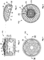
- Fig. 1
- die zuströmseitige Ansicht eines Strahlreglers, wobei diese zuströmseitige Ansicht vor allem ein dem Strahlregler zuströmseitig vorgeschaltetes Vorsatz-oder Filtersieb zeigt,
- Fig. 2
- den Strahlregler aus
Figur 1 in einem Längsschnitt durch Schnittebene VIII-VIII ausFigur 1 , wobei zu erkennen ist, dass der inFigur 2 gezeigte Strahlregler eine von der Abströmseite der Lochplatte beabstandete Prallschräge hat, die eine den lichten Durchflußquerschnitt des Strahlreglers in Strömungsrichtung verengende Einschnürung bildet, - Fig. 3
- die Lochplatte des in
Figur 1 und 2 gezeigten Strahlreglers in einem perspektivischen Teil-Längsschnitt, - Fig. 4
- die abströmseitige Stirnfläche des in den
Figuren 1 bis 3 gezeigten Strahlreglers in einer Unteransicht, - Fig. 5
- den Stahlregler gemäß den
Figuren 1 in einer auseinandergezogenen perspektivischen Einzelteildarstellung,bis 4 - Fig. 6
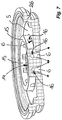
- den Strahlregler aus den
Figuren 1 in einem vergrößerten Längsschnitt, wobei die Strömungsrichtung des den Strahlregler durchfließenden Wassers durch entsprechende Pfeile angedeutet ist, undbis 5 - Fig. 7
- die Lochplatte des in den
Figuren 1 gezeigten Strahlreglers in einem vergrößerten perspektivischen Teil-Längsschnitt.bis 6
- Fig. 1
- the inflow-side view of a jet regulator, wherein this inflow-side view mainly shows an attachment or filter screen upstream of the jet regulator on the inflow side,
- Fig. 2
- off the jet regulator
FIG. 1 in a longitudinal section through section plane VIII-VIIIFIG. 1 , where it can be seen that the inFIG. 2 shown jet regulator has a spaced from the downstream side of the perforated plate baffle slope, which forms a narrow flow area of the jet regulator in the flow direction narrowing constriction, - Fig. 3
- the perforated plate of in
FIGS. 1 and 2 shown jet regulator in a perspective partial longitudinal section, - Fig. 4
- the downstream end face of the in the
FIGS. 1 to 3 shown jet controller in a bottom view, - Fig. 5
- the steel regulator according to
FIGS. 1 to 4 in an exploded perspective detail view, - Fig. 6
- the jet regulator from the
FIGS. 1 to 5 in an enlarged longitudinal section, wherein the flow direction of the jet regulator flowing through the water is indicated by corresponding arrows, and - Fig. 7
- the perforated plate in the
FIGS. 1 to 6 shown beam regulator in an enlarged perspective partial longitudinal section.
In den
Die Strahlregler-Ausführung 100 weist ein hülsenförmiges und im Querschnitt rundes Strahlreglergehäuse 2 auf.The
Die Strahlregler-Ausführung 100 in den
Im Gehäuseinnenraum des Strahlreglers 100 ist eine Lochplatte 5 vorgesehen, die eine Mehrzahl von Durchflußlöchern 6 trägt.In the housing interior of the
Zumindest ein Durchflußloch 6 und vorzugsweise alle Durchflußlöcher 6 der Lochplatte 5 erweitern sich zumindest in einem abströmseitigen Teilbereich zu ihrer Abströmseite hin kegelförmig oder konisch. Die in der Lochplatte 5 vorgesehenen Durchflußlöcher 6 sind zum Aufteilen des durchströmenden Wassers bestimmt. Durch das kegelförmige oder konische Aufspreizen des aus der Lochplatte austretenden Wassers kann sich dieses selbst bei geringen Durchflußleistungen und niedrigen Wasserdrücken praktisch über den gesamten Querschnitt des Strahlreglergehäuses 2 mit der in das Strahlreglergehäuse eingesaugten Umgebungsluft vermischen.At least one through-
Dabei erweitern sich die Durchflußlöcher 6 derart kegelförmig oder konisch, dass der aus den Durchflußlöchern 6 austretende und durch die Kegelform oder die Konizität sich erweiternde Wasserstrahl sich im Gehäuseinnenraum noch vor dem Auftreffen von Einzelstrahlen auf wenigstens ein im Gehäuseinnenraum angeordnetes Strahlformteil mit dem Einzelstrahl wenigstens eines benachbarten Durchflußloches durchmischt.The flow holes 6 extend conically or conically in such a way that the water jet emerging from the flow holes 6 and widening due to the conical shape or conicity becomes at least one adjacent one in the interior of the housing prior to the impact of individual jets on at least one beam molding arranged in the interior of the housing Durchflußloches mixed.
In den
Bei der in den
Die in den
In
In den
In
- 22
- StrahlreglergehäuseFlow regulator housing
- 33
- Außengewindeexternal thread
- 44
- Ringabsatzannular shoulder
- 55
- Lochplatteperforated plate
- 66
- Durchflußlöcher (in der Lochplatte 5)Flow holes (in the perforated plate 5)
- 77
- (radiale) Stege(radial) webs
- 88th
- Kreuzungsknotenintersection node
- 99
- (konzentrische) Stege(concentric) webs
- 1111
- (zuströmseitiges) Einsetzteil(upstream) insert part
- 1212
- (abströmseitiges) Einsetzteil(downstream) insert part
- 1313
- Ringwandung (an den Einsetzteilen 11, 12)Ring wall (on the inserts 11, 12)
- 1414
- Prallfläche (zentral auf der Lochplatte 5)Baffle (centrally on the perforated plate 5)
- 1515
- Ringwandung (zuströmseitig auf der Lochplatte 5)Ring wall (on the inflow side on the perforated plate 5)
- 1616
- Durchtrittsöffnungen (in der Ringwandung 15)Passage openings (in the annular wall 15)
- 1717
- Belüftungsöffnung (im Strahlreglergehäuse 2)Ventilation opening (in the jet regulator housing 2)
- 1818
- (doppelwandiger) Abschnitt (der Gehäuseumfangswandung)(double-walled) section (the housing peripheral wall)
- 1919
- Prallschrägeimpact slope
- 2020
- Einsetzteil (mit Prallschräge 19)Insertion part (with baffle slope 19)
- 2222
- Netzstruktur (als abströmseitige Stirnfläche des Strahlreglers)Net structure (as downstream face of the jet regulator)
- 2424
- (radiale) Stege (der abströmseitigen Stirnfläche des Strahlreglers 100)(radial) webs (the downstream end face of the jet regulator 100)
- 2525
- (konzentrische) Stege (an der abströmseitigen Stirnfläche des Strahlreglers 100)(concentric) webs (at the downstream end face of the jet regulator 100)
- 2626
- (zuströmseitiges) Gehäuseteil(upstream) housing part
- 2727
- (abströmseitiges) Gehäuseteil(downstream) housing part
- 2828
- Vorsatz- oder FiltersiebAttachment or filter screen
- 2929
- (außenseitig umlaufende) Prallfläche (der Lochplatte 5)(outside circumferential) baffle (the perforated plate 5)
- 100100
-
Strahlregler (gemäß den
Figuren 1 bis 7 )Jet regulator (according to theFIGS. 1 to 7 )
Claims (19)
- Jet regulator (100) having a jet regulator housing (2), in the housing interior of which a perforated plate (5) with a plurality of through-flow holes (6) for dividing through-flowing water is provided, on the outflow-side of which in the jet regulator housing (2) and/or at the outflow end face of the jet regulator housing (2) flow obstructions are provided which, at that location, are arranged or concentrated in a central or middle region and which divert the through-flowing water into an outer annular zone, characterised in that the perforated plate (5) has a central hole-free first deflector surface (14) which is defined by at least one annular wall (15), that the annular wall (15) is defined on the outer peripheral side by an annularly encircling second deflector surface (29), that the annular wall (15) comprises passage openings (16) oriented in the radial direction, and that on the side of the passage openings (16) disposed in the deflector surface plane, a respective through-flow hole (6) of the perforated plate (5) is provided.
- Jet regulator as claimed in claim 1, characterised in that, on the outflow side of the perforated plate (5) and at a distance therefrom, an encircling deflector slope (19) is provided which increasingly narrows the open housing cross-section in this region in the flow direction.
- Jet regulator as claimed in claim 2, characterised in that the deflector slope (19) forms the inflow side of a wall portion which is designed as at least one constriction which undulates in longitudinal cross-section.
- Jet regulator as claimed in any one of claims 1 to 3, characterised in that the jet regulator housing (2) is of multi-part design and has at least two housing parts (26, 27) which can be connected to one another preferably in a releasable manner.
- Jet regulator as claimed in claim 4, characterised in that the deflector slopes (19) are integrally formed in one piece on the housing inner periphery of an outflow-side housing part (27), and/or that the perforated plate (5) is integrally formed in one piece in the housing interior of an inflow-side housing part (26).
- Jet regulator as claimed in any one of claims 1 to 5, characterised in that at least one net or lattice structure is positioned downstream of the perforated plate (5) in the flow direction.
- Jet regulator as claimed in claim 6, characterised in that the net or lattice structure is formed from two sets of webs (7, 9) which intersect with one another at intersection nodes (8).
- Jet regulator as claimed in claim 7, characterised in that the net structure is formed from radial webs (7) and concentric webs (9) which intersect therewith at intersection nodes (8).
- Jet regulator as claimed in any one of claims 6 to 8, characterised in that at least two mutually spaced net or lattice structures are positioned downstream of the perforated plate (5) in the flow direction.
- Jet regulator as claimed in claim 8 or 9, characterised in that at least one through-flow hole (6) is aligned in the flow direction with a radial web (7) of one net structure and with a concentric web (9) of an adjacent net structure.
- Jet regulator as claimed in any one of claims 8 to 10, characterised in that the webs (7, 8) which are aligned in each case with a through-flow hole (6) overlap or intersect with one another in the flow direction of the at least one through-flow hole (6) in the different planes of these net structures.
- Jet regulator as claimed in any one of claims 8 to 11, characterised in that each net structure is formed by an insert part (11, 12) which can be inserted into the housing interior of the jet regulator housing (2).
- Jet regulator as claimed in any one of claims 7 to 12, characterised in that each insert part (11, 12) has, on the outer peripheral side, an encircling annular wall (13) to which webs (7) of the net or lattice structure are connected and are preferably integrally formed as one piece thereon.
- Jet regulator as claimed in any one of claims 8 to 13, characterised in that at least the concentric webs (9) and preferably also the radial webs (7) of a net structure which is in front in the flow direction has an identical or smaller web thickness in comparison to the webs (7, 9) of a net structure which is adjacent on the outflow side in the flow direction.
- Jet regulator as claimed in any one of claims 1 to 14, characterised in that the outflow-side end surface of the jet regulator housing (2) is formed by a net or honeycomb cell structure (21; 22), and that the net or honeycomb cell structure (21; 22) forming the outflow-side end surface is either non-releasably connected to the jet regulator housing (2) and in particular is integrally formed as one piece thereon or is formed by an insert part (23) which can be inserted into the jet regulator housing (2).
- Jet regulator as claimed in claim 15, characterised in that the net or honeycomb cell structure (21; 22) forming the outflow-side end surface of the jet regulator housing (2) is formed by webs (24, 25) which, at least in an outflow-side sub-region, narrow in the flow direction.
- Jet regulator as claimed in any one of claims 1 to 16, characterised in that the jet regulator (1, 10, 100) is designed as an aerated jet regulator which has at least one aeration opening (17) which issues in the housing interior on the outflow side of the perforated plate (5) and connects the housing interior to atmosphere.
- Jet regulator as claimed in any one of claims 1 to 17, characterised in that at least one through-flow hole (6) of the perforated plate (5) widens in a cone-shaped or conical manner at least in a downstream-side perforated portion towards its outflow side.
- Jet regulator as claimed in claim 18, characterised in that at least one through-flow hole (6) widens in a cone-shaped or conical manner at least in a downstream-side perforated portion towards its outflow side in such a way that the individual jet or spray jet - emerging from the through-flow hole (6) and widening owing to the cone shape or conicity - mixes in the housing interior - preferably still prior to the impingement of individual jets on at least one jet-forming part in the housing interior - with the individual jet of at least one adjacent through-flow hole (6).
Priority Applications (1)
| Application Number | Priority Date | Filing Date | Title |
|---|---|---|---|
| PL15003211T PL3009571T3 (en) | 2012-11-02 | 2013-08-21 | Flow regulator |
Applications Claiming Priority (2)
| Application Number | Priority Date | Filing Date | Title |
|---|---|---|---|
| DE201220010420 DE202012010420U1 (en) | 2012-11-02 | 2012-11-02 | aerator |
| EP13753278.4A EP2914784B1 (en) | 2012-11-02 | 2013-08-21 | Jet regulator |
Related Parent Applications (2)
| Application Number | Title | Priority Date | Filing Date |
|---|---|---|---|
| EP13753278.4A Division EP2914784B1 (en) | 2012-11-02 | 2013-08-21 | Jet regulator |
| EP13753278.4A Division-Into EP2914784B1 (en) | 2012-11-02 | 2013-08-21 | Jet regulator |
Publications (2)
| Publication Number | Publication Date |
|---|---|
| EP3009571A1 EP3009571A1 (en) | 2016-04-20 |
| EP3009571B1 true EP3009571B1 (en) | 2018-03-28 |
Family
ID=49036551
Family Applications (2)
| Application Number | Title | Priority Date | Filing Date |
|---|---|---|---|
| EP13753278.4A Active EP2914784B1 (en) | 2012-11-02 | 2013-08-21 | Jet regulator |
| EP15003211.8A Active EP3009571B1 (en) | 2012-11-02 | 2013-08-21 | Flow regulator |
Family Applications Before (1)
| Application Number | Title | Priority Date | Filing Date |
|---|---|---|---|
| EP13753278.4A Active EP2914784B1 (en) | 2012-11-02 | 2013-08-21 | Jet regulator |
Country Status (9)
| Country | Link |
|---|---|
| US (2) | US10280600B2 (en) |
| EP (2) | EP2914784B1 (en) |
| BR (1) | BR112014025582B1 (en) |
| DE (1) | DE202012010420U1 (en) |
| ES (2) | ES2654183T3 (en) |
| MX (1) | MX348998B (en) |
| PL (2) | PL3009571T3 (en) |
| TR (1) | TR201808463T4 (en) |
| WO (1) | WO2014067594A1 (en) |
Families Citing this family (7)
| Publication number | Priority date | Publication date | Assignee | Title |
|---|---|---|---|---|
| DE102016003010B4 (en) * | 2016-03-14 | 2017-10-26 | Neoperl Gmbh | aerator |
| CN108543430B (en) * | 2018-07-02 | 2024-02-02 | 厦门松霖科技股份有限公司 | Water outlet device |
| CN110454961A (en) * | 2019-07-29 | 2019-11-15 | 西安建筑科技大学 | It is a kind of to disappear the uneven annular water conservancy diversion orifice fitting in whirlpool for jet stream restricted clearance |
| DE202019106347U1 (en) * | 2019-11-14 | 2021-02-16 | Neoperl Gmbh | Aerator |
| US11591780B2 (en) * | 2020-04-15 | 2023-02-28 | Yeuu Deng Sanitary Facilities Industrial Co., Ltd. | Faucet aerator |
| CN112774885A (en) * | 2021-01-20 | 2021-05-11 | 厦门水魔师卫浴科技有限公司 | Multifunctional bubbler |
| DE202021106933U1 (en) * | 2021-12-20 | 2023-03-21 | Neoperl Gmbh | cavitation jet regulator |
Family Cites Families (17)
| Publication number | Priority date | Publication date | Assignee | Title |
|---|---|---|---|---|
| US3918647A (en) | 1974-01-14 | 1975-11-11 | Chemtrust Ind Corp | Foam generating apparatus |
| US4000857A (en) * | 1974-07-17 | 1977-01-04 | Moen Alfred M | Flow control aerator |
| DE3000799A1 (en) | 1980-01-11 | 1981-07-16 | Dieter Wildfang KG, 7840 Müllheim | JET CONTROLLER FOR CONNECTION TO SANITARY FITTINGS OR THE LIKE. |
| US4562960A (en) * | 1983-03-14 | 1986-01-07 | Masco Corporation Of Indiana | Pressure responsive aerator |
| US5071071A (en) * | 1990-06-05 | 1991-12-10 | Chao Tien Hsiung | Aerator structure for a water faucet |
| DE9414686U1 (en) | 1993-06-07 | 1994-11-03 | Deis Stephan | Device for triggering and interrupting the water flow from a water outlet opening |
| EP1273724B1 (en) | 2000-03-17 | 2004-01-28 | Toto Ltd. | Foam water delivery port |
| ITMN20040015A1 (en) * | 2004-07-13 | 2004-10-13 | Bpa Srl | FLUX REGULATOR |
| WO2006005099A2 (en) | 2004-07-14 | 2006-01-19 | Siegfried Kogelbauer | Flow rate limiter |
| DE102005001419B3 (en) * | 2005-01-12 | 2006-05-24 | Neoperl Gmbh | Beam regulator e.g. for nozzle, has jet division mechanism allowing water to flow into multiplicity of single jets which are provided on junction and has crossing lattice bars forming grid network |
| DE102005005433B4 (en) * | 2005-02-05 | 2006-10-19 | RST Gesellschaft für Wasserspartechnik mbH | flow regulator |
| DE102006057795B3 (en) * | 2006-12-06 | 2008-02-21 | Neoperl Gmbh | Sanitary installation unit for use as aerator, has filter sieve with dirt outlet opening, which has increased opening cross-section compared to sieve openings of filter sieve, where dirt outlet opening ends into bypass or cleaning channel |
| DE102008052541A1 (en) * | 2008-10-21 | 2010-04-22 | Neoperl Gmbh | aerator |
| CA2647917A1 (en) | 2008-12-24 | 2010-06-24 | Globe Union Industrial Corp. | Water-flow filtering structure |
| US20100163478A1 (en) * | 2008-12-30 | 2010-07-01 | Globe Union Industrial Corp. | Water-flow filtering structure |
| US9328491B2 (en) * | 2010-03-31 | 2016-05-03 | Toto Ltd. | Water spouting device |
| US20110284661A1 (en) * | 2010-05-18 | 2011-11-24 | Chang Chin-Miao | Water saving device |
-
2012
- 2012-11-02 DE DE201220010420 patent/DE202012010420U1/en not_active Expired - Lifetime
-
2013
- 2013-08-21 PL PL15003211T patent/PL3009571T3/en unknown
- 2013-08-21 BR BR112014025582-2A patent/BR112014025582B1/en active IP Right Grant
- 2013-08-21 MX MX2014012878A patent/MX348998B/en active IP Right Grant
- 2013-08-21 ES ES13753278.4T patent/ES2654183T3/en active Active
- 2013-08-21 PL PL13753278T patent/PL2914784T3/en unknown
- 2013-08-21 ES ES15003211.8T patent/ES2674646T3/en active Active
- 2013-08-21 TR TR2018/08463T patent/TR201808463T4/en unknown
- 2013-08-21 EP EP13753278.4A patent/EP2914784B1/en active Active
- 2013-08-21 WO PCT/EP2013/002520 patent/WO2014067594A1/en active Application Filing
- 2013-08-21 EP EP15003211.8A patent/EP3009571B1/en active Active
- 2013-08-21 US US14/403,472 patent/US10280600B2/en active Active
-
2019
- 2019-03-19 US US16/357,891 patent/US20190211538A1/en active Pending
Also Published As
| Publication number | Publication date |
|---|---|
| EP3009571A1 (en) | 2016-04-20 |
| US20150102133A1 (en) | 2015-04-16 |
| BR112014025582B1 (en) | 2021-06-29 |
| ES2654183T3 (en) | 2018-02-12 |
| DE202012010420U1 (en) | 2014-02-03 |
| TR201808463T4 (en) | 2018-07-23 |
| EP2914784A1 (en) | 2015-09-09 |
| MX2014012878A (en) | 2015-02-12 |
| US20190211538A1 (en) | 2019-07-11 |
| BR112014025582A2 (en) | 2017-06-20 |
| WO2014067594A1 (en) | 2014-05-08 |
| US10280600B2 (en) | 2019-05-07 |
| MX348998B (en) | 2017-07-06 |
| PL2914784T3 (en) | 2018-03-30 |
| ES2674646T3 (en) | 2018-07-03 |
| EP2914784B1 (en) | 2017-11-01 |
| PL3009571T3 (en) | 2018-08-31 |
Similar Documents
| Publication | Publication Date | Title |
|---|---|---|
| EP3009571B1 (en) | Flow regulator | |
| DE102012021361B4 (en) | aerator | |
| DE10246334B4 (en) | Sanitary installation part | |
| EP1836356B1 (en) | Jet regulator | |
| DE10246333B4 (en) | aerator | |
| EP3596277B1 (en) | Sanitary insert unit | |
| EP3510204B1 (en) | Sanitary insert unit | |
| DE202015008802U1 (en) | Sanitary outlet unit | |
| EP3219860B1 (en) | Beam controller | |
| DE202006003342U1 (en) | Flow controller for aerating water is fitted with circular grid made up of concentric rings and radial bars, water being divided into several streams as it flows through grid and strikes points where they cross | |
| DE102009011345B4 (en) | aerator | |
| EP4077821B1 (en) | Aerator | |
| DE102006009828B3 (en) | Jet regulator, has jet dispersion device provided for dividing water flow into set of individual streams, where each individual stream strikes on ridge of grid that is provided at downstream of dispersion side | |
| DE102015016796A1 (en) | Sanitary outlet unit | |
| DE102016015807A1 (en) | Sanitary insert unit | |
| DE102016010842B4 (en) | Sanitary insert unit | |
| DE102016003010B4 (en) | aerator | |
| DE10146788A1 (en) | Water jet control unit has a housing with a water flow divider, between the inflow and outflow openings, and a ring wall to restrict the flow cross section near the outflow | |
| DE102019135057A1 (en) | Aerator | |
| DE202005000119U1 (en) | Stream controller comprises a stream separating unit for dividing a flowing water stream into a number of individual streams so that an individual stream hits a node point of crossing lattice rods of a lattice | |
| DE102016015732A1 (en) | aerator |
Legal Events
| Date | Code | Title | Description |
|---|---|---|---|
| PUAI | Public reference made under article 153(3) epc to a published international application that has entered the european phase |
Free format text: ORIGINAL CODE: 0009012 |
|
| AC | Divisional application: reference to earlier application |
Ref document number: 2914784 Country of ref document: EP Kind code of ref document: P |
|
| AK | Designated contracting states |
Kind code of ref document: A1 Designated state(s): AL AT BE BG CH CY CZ DE DK EE ES FI FR GB GR HR HU IE IS IT LI LT LU LV MC MK MT NL NO PL PT RO RS SE SI SK SM TR |
|
| AX | Request for extension of the european patent |
Extension state: BA ME |
|
| 17P | Request for examination filed |
Effective date: 20161020 |
|
| RBV | Designated contracting states (corrected) |
Designated state(s): AL AT BE BG CH CY CZ DE DK EE ES FI FR GB GR HR HU IE IS IT LI LT LU LV MC MK MT NL NO PL PT RO RS SE SI SK SM TR |
|
| RIN1 | Information on inventor provided before grant (corrected) |
Inventor name: TEMPEL, MARC |
|
| GRAP | Despatch of communication of intention to grant a patent |
Free format text: ORIGINAL CODE: EPIDOSNIGR1 |
|
| RIC1 | Information provided on ipc code assigned before grant |
Ipc: E03C 1/084 20060101AFI20170922BHEP |
|
| INTG | Intention to grant announced |
Effective date: 20171024 |
|
| GRAS | Grant fee paid |
Free format text: ORIGINAL CODE: EPIDOSNIGR3 |
|
| GRAJ | Information related to disapproval of communication of intention to grant by the applicant or resumption of examination proceedings by the epo deleted |
Free format text: ORIGINAL CODE: EPIDOSDIGR1 |
|
| GRAL | Information related to payment of fee for publishing/printing deleted |
Free format text: ORIGINAL CODE: EPIDOSDIGR3 |
|
| GRAR | Information related to intention to grant a patent recorded |
Free format text: ORIGINAL CODE: EPIDOSNIGR71 |
|
| GRAA | (expected) grant |
Free format text: ORIGINAL CODE: 0009210 |
|
| INTC | Intention to grant announced (deleted) | ||
| AC | Divisional application: reference to earlier application |
Ref document number: 2914784 Country of ref document: EP Kind code of ref document: P |
|
| AK | Designated contracting states |
Kind code of ref document: B1 Designated state(s): AL AT BE BG CH CY CZ DE DK EE ES FI FR GB GR HR HU IE IS IT LI LT LU LV MC MK MT NL NO PL PT RO RS SE SI SK SM TR |
|
| INTG | Intention to grant announced |
Effective date: 20180220 |
|
| REG | Reference to a national code |
Ref country code: GB Ref legal event code: FG4D Free format text: NOT ENGLISH |
|
| REG | Reference to a national code |
Ref country code: CH Ref legal event code: EP |
|
| REG | Reference to a national code |
Ref country code: AT Ref legal event code: REF Ref document number: 983572 Country of ref document: AT Kind code of ref document: T Effective date: 20180415 |
|
| REG | Reference to a national code |
Ref country code: IE Ref legal event code: FG4D Free format text: LANGUAGE OF EP DOCUMENT: GERMAN |
|
| REG | Reference to a national code |
Ref country code: DE Ref legal event code: R096 Ref document number: 502013009807 Country of ref document: DE |
|
| REG | Reference to a national code |
Ref country code: ES Ref legal event code: FG2A Ref document number: 2674646 Country of ref document: ES Kind code of ref document: T3 Effective date: 20180703 |
|
| PG25 | Lapsed in a contracting state [announced via postgrant information from national office to epo] |
Ref country code: HR Free format text: LAPSE BECAUSE OF FAILURE TO SUBMIT A TRANSLATION OF THE DESCRIPTION OR TO PAY THE FEE WITHIN THE PRESCRIBED TIME-LIMIT Effective date: 20180328 Ref country code: LT Free format text: LAPSE BECAUSE OF FAILURE TO SUBMIT A TRANSLATION OF THE DESCRIPTION OR TO PAY THE FEE WITHIN THE PRESCRIBED TIME-LIMIT Effective date: 20180328 Ref country code: NO Free format text: LAPSE BECAUSE OF FAILURE TO SUBMIT A TRANSLATION OF THE DESCRIPTION OR TO PAY THE FEE WITHIN THE PRESCRIBED TIME-LIMIT Effective date: 20180628 Ref country code: FI Free format text: LAPSE BECAUSE OF FAILURE TO SUBMIT A TRANSLATION OF THE DESCRIPTION OR TO PAY THE FEE WITHIN THE PRESCRIBED TIME-LIMIT Effective date: 20180328 |
|
| REG | Reference to a national code |
Ref country code: NL Ref legal event code: MP Effective date: 20180328 |
|
| REG | Reference to a national code |
Ref country code: LT Ref legal event code: MG4D |
|
| PG25 | Lapsed in a contracting state [announced via postgrant information from national office to epo] |
Ref country code: LV Free format text: LAPSE BECAUSE OF FAILURE TO SUBMIT A TRANSLATION OF THE DESCRIPTION OR TO PAY THE FEE WITHIN THE PRESCRIBED TIME-LIMIT Effective date: 20180328 Ref country code: BG Free format text: LAPSE BECAUSE OF FAILURE TO SUBMIT A TRANSLATION OF THE DESCRIPTION OR TO PAY THE FEE WITHIN THE PRESCRIBED TIME-LIMIT Effective date: 20180628 Ref country code: GR Free format text: LAPSE BECAUSE OF FAILURE TO SUBMIT A TRANSLATION OF THE DESCRIPTION OR TO PAY THE FEE WITHIN THE PRESCRIBED TIME-LIMIT Effective date: 20180629 Ref country code: RS Free format text: LAPSE BECAUSE OF FAILURE TO SUBMIT A TRANSLATION OF THE DESCRIPTION OR TO PAY THE FEE WITHIN THE PRESCRIBED TIME-LIMIT Effective date: 20180328 Ref country code: SE Free format text: LAPSE BECAUSE OF FAILURE TO SUBMIT A TRANSLATION OF THE DESCRIPTION OR TO PAY THE FEE WITHIN THE PRESCRIBED TIME-LIMIT Effective date: 20180328 |
|
| PG25 | Lapsed in a contracting state [announced via postgrant information from national office to epo] |
Ref country code: MT Free format text: LAPSE BECAUSE OF FAILURE TO SUBMIT A TRANSLATION OF THE DESCRIPTION OR TO PAY THE FEE WITHIN THE PRESCRIBED TIME-LIMIT Effective date: 20180328 |
|
| PG25 | Lapsed in a contracting state [announced via postgrant information from national office to epo] |
Ref country code: RO Free format text: LAPSE BECAUSE OF FAILURE TO SUBMIT A TRANSLATION OF THE DESCRIPTION OR TO PAY THE FEE WITHIN THE PRESCRIBED TIME-LIMIT Effective date: 20180328 Ref country code: AL Free format text: LAPSE BECAUSE OF FAILURE TO SUBMIT A TRANSLATION OF THE DESCRIPTION OR TO PAY THE FEE WITHIN THE PRESCRIBED TIME-LIMIT Effective date: 20180328 Ref country code: NL Free format text: LAPSE BECAUSE OF FAILURE TO SUBMIT A TRANSLATION OF THE DESCRIPTION OR TO PAY THE FEE WITHIN THE PRESCRIBED TIME-LIMIT Effective date: 20180328 Ref country code: EE Free format text: LAPSE BECAUSE OF FAILURE TO SUBMIT A TRANSLATION OF THE DESCRIPTION OR TO PAY THE FEE WITHIN THE PRESCRIBED TIME-LIMIT Effective date: 20180328 |
|
| PG25 | Lapsed in a contracting state [announced via postgrant information from national office to epo] |
Ref country code: SM Free format text: LAPSE BECAUSE OF FAILURE TO SUBMIT A TRANSLATION OF THE DESCRIPTION OR TO PAY THE FEE WITHIN THE PRESCRIBED TIME-LIMIT Effective date: 20180328 Ref country code: CZ Free format text: LAPSE BECAUSE OF FAILURE TO SUBMIT A TRANSLATION OF THE DESCRIPTION OR TO PAY THE FEE WITHIN THE PRESCRIBED TIME-LIMIT Effective date: 20180328 Ref country code: SK Free format text: LAPSE BECAUSE OF FAILURE TO SUBMIT A TRANSLATION OF THE DESCRIPTION OR TO PAY THE FEE WITHIN THE PRESCRIBED TIME-LIMIT Effective date: 20180328 |
|
| PG25 | Lapsed in a contracting state [announced via postgrant information from national office to epo] |
Ref country code: PT Free format text: LAPSE BECAUSE OF FAILURE TO SUBMIT A TRANSLATION OF THE DESCRIPTION OR TO PAY THE FEE WITHIN THE PRESCRIBED TIME-LIMIT Effective date: 20180730 |
|
| REG | Reference to a national code |
Ref country code: DE Ref legal event code: R097 Ref document number: 502013009807 Country of ref document: DE |
|
| PG25 | Lapsed in a contracting state [announced via postgrant information from national office to epo] |
Ref country code: DK Free format text: LAPSE BECAUSE OF FAILURE TO SUBMIT A TRANSLATION OF THE DESCRIPTION OR TO PAY THE FEE WITHIN THE PRESCRIBED TIME-LIMIT Effective date: 20180328 |
|
| PLBE | No opposition filed within time limit |
Free format text: ORIGINAL CODE: 0009261 |
|
| STAA | Information on the status of an ep patent application or granted ep patent |
Free format text: STATUS: NO OPPOSITION FILED WITHIN TIME LIMIT |
|
| 26N | No opposition filed |
Effective date: 20190103 |
|
| PG25 | Lapsed in a contracting state [announced via postgrant information from national office to epo] |
Ref country code: MC Free format text: LAPSE BECAUSE OF FAILURE TO SUBMIT A TRANSLATION OF THE DESCRIPTION OR TO PAY THE FEE WITHIN THE PRESCRIBED TIME-LIMIT Effective date: 20180328 |
|
| REG | Reference to a national code |
Ref country code: CH Ref legal event code: PL |
|
| PG25 | Lapsed in a contracting state [announced via postgrant information from national office to epo] |
Ref country code: CH Free format text: LAPSE BECAUSE OF NON-PAYMENT OF DUE FEES Effective date: 20180831 Ref country code: LU Free format text: LAPSE BECAUSE OF NON-PAYMENT OF DUE FEES Effective date: 20180821 Ref country code: LI Free format text: LAPSE BECAUSE OF NON-PAYMENT OF DUE FEES Effective date: 20180831 |
|
| REG | Reference to a national code |
Ref country code: BE Ref legal event code: MM Effective date: 20180831 |
|
| PG25 | Lapsed in a contracting state [announced via postgrant information from national office to epo] |
Ref country code: SI Free format text: LAPSE BECAUSE OF FAILURE TO SUBMIT A TRANSLATION OF THE DESCRIPTION OR TO PAY THE FEE WITHIN THE PRESCRIBED TIME-LIMIT Effective date: 20180328 |
|
| PG25 | Lapsed in a contracting state [announced via postgrant information from national office to epo] |
Ref country code: FR Free format text: LAPSE BECAUSE OF NON-PAYMENT OF DUE FEES Effective date: 20180831 Ref country code: BE Free format text: LAPSE BECAUSE OF NON-PAYMENT OF DUE FEES Effective date: 20180831 |
|
| REG | Reference to a national code |
Ref country code: AT Ref legal event code: MM01 Ref document number: 983572 Country of ref document: AT Kind code of ref document: T Effective date: 20180821 |
|
| PG25 | Lapsed in a contracting state [announced via postgrant information from national office to epo] |
Ref country code: AT Free format text: LAPSE BECAUSE OF NON-PAYMENT OF DUE FEES Effective date: 20180821 |
|
| PG25 | Lapsed in a contracting state [announced via postgrant information from national office to epo] |
Ref country code: IE Free format text: LAPSE BECAUSE OF NON-PAYMENT OF DUE FEES Effective date: 20180821 Ref country code: CY Free format text: LAPSE BECAUSE OF FAILURE TO SUBMIT A TRANSLATION OF THE DESCRIPTION OR TO PAY THE FEE WITHIN THE PRESCRIBED TIME-LIMIT Effective date: 20180328 Ref country code: HU Free format text: LAPSE BECAUSE OF FAILURE TO SUBMIT A TRANSLATION OF THE DESCRIPTION OR TO PAY THE FEE WITHIN THE PRESCRIBED TIME-LIMIT; INVALID AB INITIO Effective date: 20130821 Ref country code: MK Free format text: LAPSE BECAUSE OF NON-PAYMENT OF DUE FEES Effective date: 20180328 |
|
| PG25 | Lapsed in a contracting state [announced via postgrant information from national office to epo] |
Ref country code: IS Free format text: LAPSE BECAUSE OF FAILURE TO SUBMIT A TRANSLATION OF THE DESCRIPTION OR TO PAY THE FEE WITHIN THE PRESCRIBED TIME-LIMIT Effective date: 20180728 |
|
| PGFP | Annual fee paid to national office [announced via postgrant information from national office to epo] |
Ref country code: TR Payment date: 20220815 Year of fee payment: 10 Ref country code: ES Payment date: 20220919 Year of fee payment: 10 |
|
| PGFP | Annual fee paid to national office [announced via postgrant information from national office to epo] |
Ref country code: PL Payment date: 20220809 Year of fee payment: 10 |
|
| PGFP | Annual fee paid to national office [announced via postgrant information from national office to epo] |
Ref country code: IT Payment date: 20230831 Year of fee payment: 11 Ref country code: GB Payment date: 20230824 Year of fee payment: 11 |
|
| PGFP | Annual fee paid to national office [announced via postgrant information from national office to epo] |
Ref country code: DE Payment date: 20230808 Year of fee payment: 11 |