EP3009571B1 - Regulateur de debit - Google Patents
Regulateur de debit Download PDFInfo
- Publication number
- EP3009571B1 EP3009571B1 EP15003211.8A EP15003211A EP3009571B1 EP 3009571 B1 EP3009571 B1 EP 3009571B1 EP 15003211 A EP15003211 A EP 15003211A EP 3009571 B1 EP3009571 B1 EP 3009571B1
- Authority
- EP
- European Patent Office
- Prior art keywords
- jet regulator
- housing
- jet
- perforated plate
- net
- Prior art date
- Legal status (The legal status is an assumption and is not a legal conclusion. Google has not performed a legal analysis and makes no representation as to the accuracy of the status listed.)
- Active
Links
- XLYOFNOQVPJJNP-UHFFFAOYSA-N water Substances O XLYOFNOQVPJJNP-UHFFFAOYSA-N 0.000 claims description 64
- 230000002093 peripheral effect Effects 0.000 claims description 11
- 239000007921 spray Substances 0.000 claims description 4
- 238000005273 aeration Methods 0.000 claims 1
- 239000012080 ambient air Substances 0.000 description 11
- 238000009423 ventilation Methods 0.000 description 8
- 239000003570 air Substances 0.000 description 5
- 238000003780 insertion Methods 0.000 description 3
- 230000037431 insertion Effects 0.000 description 3
- 238000002156 mixing Methods 0.000 description 3
- 238000000465 moulding Methods 0.000 description 3
- 238000011144 upstream manufacturing Methods 0.000 description 3
- 229910000831 Steel Inorganic materials 0.000 description 2
- 238000011161 development Methods 0.000 description 2
- 230000018109 developmental process Effects 0.000 description 2
- 238000000265 homogenisation Methods 0.000 description 2
- 239000002184 metal Substances 0.000 description 2
- 239000000203 mixture Substances 0.000 description 2
- 239000008234 soft water Substances 0.000 description 2
- 239000010959 steel Substances 0.000 description 2
- 238000005276 aerator Methods 0.000 description 1
- 238000000354 decomposition reaction Methods 0.000 description 1
- 244000144992 flock Species 0.000 description 1
- 238000002347 injection Methods 0.000 description 1
- 239000007924 injection Substances 0.000 description 1
- 238000004519 manufacturing process Methods 0.000 description 1
- 239000002245 particle Substances 0.000 description 1
Images


Classifications
-
- E—FIXED CONSTRUCTIONS
- E03—WATER SUPPLY; SEWERAGE
- E03C—DOMESTIC PLUMBING INSTALLATIONS FOR FRESH WATER OR WASTE WATER; SINKS
- E03C1/00—Domestic plumbing installations for fresh water or waste water; Sinks
- E03C1/02—Plumbing installations for fresh water
- E03C1/08—Jet regulators or jet guides, e.g. anti-splash devices
- E03C1/084—Jet regulators with aerating means
-
- E—FIXED CONSTRUCTIONS
- E03—WATER SUPPLY; SEWERAGE
- E03C—DOMESTIC PLUMBING INSTALLATIONS FOR FRESH WATER OR WASTE WATER; SINKS
- E03C1/00—Domestic plumbing installations for fresh water or waste water; Sinks
- E03C1/02—Plumbing installations for fresh water
- E03C1/08—Jet regulators or jet guides, e.g. anti-splash devices
- E03C1/086—Jet regulators or jet guides, easily mountable on the outlet of taps
Definitions
- the invention relates to a jet regulator with a jet regulator housing, in the housing interior of a perforated plate is provided with a plurality of fürflußlöchern for dividing the water flowing through, are provided on the downstream side of the perforated plate in the jet regulator housing and / or at the Abströmstirn scene the jet regulator flow obstacles, there in a central or central area are arranged or concentrated and divert the water flowing through into an outer annular zone.
- Jet regulator of the type mentioned are already known in various designs. Such jet regulators are mounted on the water outlet of a sanitary outlet fitting to produce a homogeneous and laterally non-splashing water jet there. It has also created aerator, which aerate the escaping water steel and mixing the water flowing through it with the ambient air.
- a jet regulator of the type mentioned with a jet regulator housing in the housing interior a perforated plate with a plurality is provided by flow holes for dividing the water flowing through.
- a perforated plate with a plurality is provided by flow holes for dividing the water flowing through.
- On the downstream side of the perforated plate insertion parts are inserted into the jet regulator housing, each having a arranged in a direction transverse to the flow plane network structure of a family of radial webs, which intersect at intersection nodes with a family of concentric webs.
- a filter screen On the inflow side of the perforated plate, a filter screen is provided, which has a centrally arranged Schmutzauslassö réelle with an enlarged compared to the screen openings of the filter screen clear opening cross-section.
- the Schmutzauslassö réelle can be closed by means of the valve body of a valve which is movable from its open position under the back pressure of the incoming water against the restoring force of a return spring in its closed position and is always held by the inflowing water in this closed position.
- a guide pin is formed, which passes through a central guide opening in the perforated plate.
- a centrally oriented grid is formed, which offers less flow possibilities in its center than at the outer edge and thus forms a flow obstacle, which deflects the water flowing through into the outer annular zone.
- this previously known jet regulator requires a certain flow and a sufficient water pressure in the pipeline network, so that the water flowing through the valve body can press against the restoring force of the return spring in the closed position of the valve.
- a ventilated jet regulator which has in its jet regulator housing a perforated plate having a plurality of flow holes, which in concentric hole circles on the Perforated plate are arranged and which should divide the water flowing through the jet regulator housing into a corresponding number of individual beams. Since the flow-through holes narrow the clear flow area in the area of the perforated plate, the water flowing through in the flow-through holes experiences an increase in speed, which causes a negative pressure on the outflow side of the perforated plate according to the Bernoulli equation.
- a jet regulator with a jet regulator housing in the housing interior a perforated plate is provided which has flow holes, which have a constant clear cross-section in the flow direction.
- the perforated plate is followed by a baffle cone in the flow direction, which forms a constriction in the flow area of the previously known jet regulator.
- the individual beams generated in the perforated plate can tear the ambient air in the housing interior of the jet regulator housing with him and then meet such on the inclined surface of the impact cone that the aerated individual jets are broken up and mixed with the entrained air.
- the prior art jet regulators require a certain flow and sufficient water pressure in the pipeline network, so that sufficient negative pressure is generated on the downstream side of serving as a jet separator perforated plate to suck ambient air into the housing interior of the jet regulator housing.
- the negative pressure formed at low flow and low water pressures is usually not sufficient to mix the ambient air with the water flowing through can.
- jet regulator of the type mentioned, which is also at low flow and / or low water pressures, as they are often sought, for example, for water saving purposes, a sufficiently ventilated and accordingly perlender-soft water jet is able to produce.
- the jet regulator according to the invention should preferably be interchangeable with the known jet regulator designs.
- the perforated plate has a central hole-free first baffle which bounds at least one annular wall, that the annular wall is bounded on the outer peripheral side of an annular peripheral second baffle that the annular wall in the radial Has directionally oriented passages, and that on the in the Plane surface-level side of the passage openings each have a flow hole of the perforated plate is provided.
- flow obstacles are provided on the outflow side of the perforated plate in the jet regulator housing and / or on the Abströmstirn survey the jet regulator housing, which are arranged or concentrated there in a central or central area and redirect the water flowing through into an outer annular zone, which in contrast no or has a smaller number or total area of flow obstacles.
- the water flowing through it becomes a central or central region by means of the flow obstacles from at least partially deflected into an outer annular zone, which forms the outer periphery of the exiting water jet.
- the perforated plate on a central first baffle which is bounded by at least one annular wall.
- This annular wall has radially oriented through openings, which are spaced apart from each other over the circumference of the annular wall.
- a second baffle surface which extends around the outside of the ring wall and which is preferably arranged in the plane of the central baffle surface.
- the water jet formed in the jet regulator according to the invention is therefore distinguished by a voluminous discharge jet pattern and by good air mixing of the water flowing through, even at low flow rates and low water pressures.
- An advantageous embodiment according to the invention provides that on the downstream side of the perforated plate at a distance from this on the housing inner circumference a circumferential baffle slope is provided, which increasingly narrows the clear housing cross-section in this area in the flow direction.
- the exiting from the flow holes and already enriched with air water meets at a distance to the perforated plate on a baffle, which additionally mixes and divides the already treated water before the thus enriched with air water as a homogeneous, non- spouting and pearly-soft water jet can escape from the jet regulator.
- a particularly easy to manufacture embodiment according to the invention provides that the baffle slope forms the inflow side of a Wandungsabitess, which is configured as at least one wavy constriction in longitudinal section.
- the impact bevel can be designed as an inner peripheral side projection or inner peripheral side projection of the housing peripheral wall and can be integrally connected to the jet regulator housing or a jet regulator housing part.
- baffle slope is formed as a wall portion of an insertable into the jet regulator housing annular or sleeve-shaped insert.
- the jet regulator housing is designed in several parts and has at least two, preferably releasably connectable housing parts.
- the impact bevel is integrally formed on the housing inner circumference of a downstream housing part and / or that the perforated plate is integrally formed in the housing interior of an inflow-side housing part.
- the perforated plate can be connected downstream of at least one mesh or grid structure in the flow direction.
- the tapered or conically emerging from the flow holes and impinging on the at least one network or lattice water is braked there and decomposed with the adjacent disassembled portions of emerging from the adjacent flow holes water to then emerge as a soft overall beam from the jet regulator can.
- Such a lattice structure can also be formed by a pickled metal screen, which is formed from two sets of preferably rectangularly interwoven metal wires, an embodiment is preferred in which the network or lattice structure is formed from two sets of webs crossing each other at intersecting nodes.
- Such a network or lattice structure, which is formed from two flocks, at intersection nodes crossing webs, can be produced in a simple manner as a plastic injection molded part.
- a preferred embodiment according to the invention provides that the at least one, the perforated plate in the flow direction downstream network structure of radial webs and thus crossing at crossing nodes concentric webs is formed.
- the perforated plate is followed in the direction of flow by at least two network or grid structures spaced apart from one another.
- a preferred development according to the invention provides that at least one flow hole in the flow direction is aligned with a radial web of a network structure and with a concentric web of an adjacent network structure.
- the divided in the perforated plate water flows out of the flow holes of the perforated plate less than single jet and rather than spray cone.
- each with a flow hole aligned webs overlap or intersect in the flow direction of the at least one Naturalflußloches in the various levels of network or grid structures.
- each mesh or lattice structure is formed by an insertion part which can be inserted into the housing interior of the jet regulator housing.
- each insert part has on the outer peripheral side a circumferential annular wall, to which webs of the mesh or grid structure are held and preferably integrally formed.
- the breaking up and dividing of the spray cone emerging from the throughflow holes of the perforated plate is further promoted if at least the concentric webs and preferably also the radial webs of a network structure in front in the direction of flow has an equal or smaller web thickness compared to the webs of a network structure adjacent downstream.
- the flow holes provided in the perforated plate can be arranged on concentric hole circles.
- a preferred embodiment according to the invention provides that the perforated plate has a central hole-free baffle which bounds at least one annular wall, that the at least one annular wall has radially oriented passage openings, and that on the arranged in the baffle plane side of the flow openings in each case a fürflußloch the perforated plate is provided.
- the water diverted in this way in the area of the annular wall becomes first braked, deflected to the side and mixed by optionally in opposite directions flowing towards each other streams before it can flow through the through holes of the perforated plate and can emerge on the downstream side of the perforated plate in the form of a corresponding number of Sprühkegeln.
- the outflow-side end face of the jet regulator housing is formed by a net or honeycomb cell structure, and if the net or honeycomb cell structure forming the downstream end face is either inseparably connected to the jet regulator housing and in particular integrally formed or formed by an insert which can be inserted into the jet regulator housing.
- the homogenization of the exiting from the jet regulator overall jet is still favored when the net or honeycomb cell structure forming the downstream end face of the jet regulator housing is formed by webs which taper at least in a downstream portion in the flow direction.
- a preferred embodiment according to the invention provides that the jet regulator according to the invention is designed as a ventilated jet regulator, in whose housing interior at least one ventilation opening opens, which connects the housing interior with the atmosphere. So that at least one ventilation opening can connect the housing interior with the atmosphere, at least one ventilation channel may be provided in a double-walled portion of the jet regulator housing or in an annular gap surrounding the jet regulator housing, which is designed to be open to the atmosphere.
- a preferred embodiment according to the invention provides that at least one flow hole of the perforated plate widens conically or conically towards its downstream side.
- the jet regulator according to the invention has a jet regulator housing, in the housing interior of which a perforated plate extending, for example, over the housing cross-section is provided.
- the perforated plate has a plurality of flow holes intended to divide the flowing water.
- At least one of the flow holes provided in the perforated plate widens increasingly conically or conically towards its downstream side and preferably as far as the downstream side.
- the good air mixing of the water flowing through is favored even at low flow rates and low water pressures, if at least one flow hole in such a conical or conical widening to its downstream side, that emerging from the flow hole and by the conical shape or conicity widening single beam itself in the housing interior even before the impingement of individual jets on at least one arranged in the housing interior Mixed jet molding with the single jet of at least one adjacent flow hole.
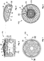
- FIGS. 1 to 7 an embodiment 100 of a jet regulator is shown.
- the jet regulator version 100 is intended to be mounted on the water outlet of a sanitary spout to form a homogeneous and laterally non-splashing jet of water there.
- the jet regulator design 100 is designed as a ventilated jet regulator, in which the water flowing through is mixed with ambient air and enriched.
- the jet regulator embodiment 100 has a sleeve-shaped and in cross section round jet regulator housing 2.
- the jet regulator version 100 in the FIGS. 1 to 7 is to be mounted with a sleeve-shaped outlet nozzle not shown here at the water outlet of the outlet fitting after the jet regulator 100 has been inserted from the inflow side sleeve opening of the outlet mouthpiece in the sleeve interior until a ring shoulder 4 rests on the outer periphery of the jet regulator housing 2 on an inner peripheral side arranged in the outlet nozzle support ,
- a perforated plate 5 is provided, which carries a plurality of Autoflußlöchern 6.
- At least one through-hole 6 and preferably all through-holes 6 of the perforated plate 5 extend conically or conically at least in an outflow-side partial region to their downstream side.
- the provided in the perforated plate 5 through holes 6 are intended for dividing the water flowing through. Due to the conical or conical spreading of the water emerging from the perforated plate, it can mix with the ambient air sucked into the jet regulator housing, even at low flow rates and low water pressures practically over the entire cross section of the jet regulator housing 2.
- the flow holes 6 extend conically or conically in such a way that the water jet emerging from the flow holes 6 and widening due to the conical shape or conicity becomes at least one adjacent one in the interior of the housing prior to the impact of individual jets on at least one beam molding arranged in the interior of the housing fürflußloches mixed.
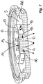
- the perforated plate 2 provided in the jet regulator embodiment 100 has a central first baffle surface 14, which is delimited by at least one annular wall 15.
- This annular wall 15 has oriented in the radial direction through openings 16, which are spaced apart here over the circumference of the annular wall 15 from each other.
- jet regulator embodiment 100 enforce the ventilation openings 17, the jet regulator housing 2 in the radial direction and are connected to the outside of the jet regulator housing 2 with a ventilation channel, which is formed as an annular gap between the housing outer circumference of the jet regulator housing 2 and the inner circumference of the outlet nozzle and the downstream end of outlet nozzle and Jet regulator 100 is open to the atmosphere.
- the in the FIGS. 1 to 7 shown jet regulator embodiment 100 has on the downstream side of the perforated plate 2 at a distance from this on the housing inner circumference a circumferential baffle slope 19, which increasingly narrows the clear housing cross-section in this area in the flow direction.
- This baffle slope 19 is formed by the inflow side of a wall section designed as a wavy constriction in longitudinal section.
- the wall portion having the baffle slope 19 is here as an insertable into the jet regulator housing 2 ring or sleeve-shaped insert 20th designed.
- the downstream end face of the jet regulator 100 is formed by a mesh structure 22 or a honeycomb cell structure. While the network or honeycomb cell structure 22 forming the outflow-side end face of the jet regulator 100 is permanently connected to the jet regulator housing 2, in another jet regulator embodiment not shown here, the outlet structure can be formed by an insert part which can be inserted into the jet regulator housing 2. From a comparison of FIGS. 2 and 4 It can be seen that the network structure 22 forming the outflow-side end face of the jet regulator 100 is formed by radial and concentric webs 24, 25 which taper at least in an outflow-side subregion in the flow direction. Since these webs 24, 25 taper in the flow direction at least in a downstream part, homogenization and equalization of the water emerging from the jet regulator housing 2 by the network structure is additionally promoted in the form of a homogeneous overall jet.
- the jet regulator housing 2 is formed here by two housing parts 26, 27 which can be detachably connected to one another and are preferably latchable with one another, of which the front housing part 26 on the inflow side is integrally connected to the perforated plate 6. So that the dirt particles possibly entrained in the water can not impair the proper functioning of the jet regulator, the jet regulator housing 2 is preceded by an attachment or filter screen 28, which is held detachably on the inflow-side housing part 26 here.
- This attachment or filter screen 28 has a multiplicity of round or rectangular, in particular hexagonal, filter or sieve openings.
Claims (19)
- Régulateur de débit (100) avec un corps de régulateur de débit (2) dans l'espace intérieur duquel il est prévu une plaque perforée (5) avec une multiplicité de trous d'écoulement (6) pour la division de l'eau qui le traverse, sur le côté aval de laquelle il est prévu dans le corps de régulateur de débit (2) et/ou sur le côté frontal aval du corps de régulateur de débit (2) des obstacles à l'écoulement, qui y sont disposés ou concentrés dans une région centrale ou médiane et qui dévient l'eau qui le traverse dans une zone annulaire extérieure, caractérisé en ce que la plaque perforée (5) comporte une première face d'impact centrale (14) sans trous, qu'entoure au moins une paroi annulaire (15), en ce que la paroi annulaire (15) est entourée sur son côté périphérique extérieur par une deuxième face d'impact périphérique de forme annulaire (29), en ce que la paroi annulaire (15) présente des orifices de passage (16) orientés en direction radiale et en ce qu'il est prévu sur le côté des orifices de passage (16) disposé dans le plan de la face d'impact chaque fois un trou d'écoulement (6) de la plaque perforée (5).
- Régulateur de débit selon la revendication 1, caractérisé en ce qu'il est prévu sur le côté aval de la plaque perforée (5) à distance de celle-là une face inclinée d'impact périphérique (19), qui rétrécit de plus en plus dans la direction d'écoulement la section transversale libre du corps dans cette région.
- Régulateur de débit selon la revendication 2, caractérisé en ce que la face inclinée d'impact (19) forme le côté amont d'une partie de paroi qui est réalisée sous la forme d'au moins un rétrécissement ondulé en coupe longitudinale.
- Régulateur de débit selon l'une quelconque des revendications 1 à 3, caractérisé en ce que le corps de régulateur de débit (2) est réalisé en plusieurs parties et comporte au moins deux parties de corps (26, 27) pouvant être assemblées l'une à l'autre de préférence de façon séparable.
- Régulateur de débit selon la revendication 4, caractérisé en ce que la face inclinée d'impact (19) est façonnée d'une seule pièce sur la périphérie intérieure du corps d'une partie de corps aval (27) et/ou en ce que la plaque perforée (5) est façonnée d'une seule pièce dans l'espace intérieur du corps d'une partie de corps amont (26).
- Régulateur de débit selon l'une quelconque des revendications 1 à 5, caractérisé en ce que la plaque perforée (5) est suivie dans la direction d'écoulement par au moins une structure de treillis ou de grille.
- Régulateur de débit selon la revendication 6, caractérisé en ce que la structure de treillis ou de grille est formée de deux faisceaux de nervures (7, 9) se croisant mutuellement en des noeuds de croisement (8).
- Régulateur de débit selon la revendication 7, caractérisé en ce que la structure de treillis est formée de nervures radiales (7) et de nervures concentriques (9) croisant celles-là en des noeuds de croisement (8).
- Régulateur de débit selon l'une quelconque des revendications 6 à 8, caractérisé en ce que la plaque perforée (5) est suivie dans la direction d'écoulement par au moins deux structures de treillis ou de grille espacées l'une de l'autre.
- Régulateur de débit selon la revendication 8 ou 9, caractérisé en ce qu'au moins un trou d'écoulement (6) est aligné dans la direction d'écoulement avec une nervure radiale (7) d'une première structure de treillis ainsi qu'avec une nervure concentrique (9) d'une structure de treillis voisine.
- Régulateur de débit selon l'une quelconque des revendications 8 à 10, caractérisé en ce que les nervures (7, 8) respectivement alignées avec un trou d'écoulement (6) se recouvrent ou se croisent dans la direction d'écoulement dudit au moins un trou d'écoulement (6) dans les différents plans de ces structures de treillis.
- Régulateur de débit selon l'une quelconque des revendications 8 à 11, caractérisé en ce que chaque structure de treillis est formée par une pièce d'insertion (11, 12) insérable dans l'espace intérieur de corps du corps de régulateur de débit (2).
- Régulateur de débit selon l'une quelconque des revendications 7 à 12, caractérisé en ce que chaque pièce d'insertion (11, 12) présente sur le côté du pourtour extérieur une paroi annulaire périphérique (13), à laquelle des nervures (7) de la structure de treillis ou de grille sont assemblées et sont de préférence façonnées d'une seule pièce.
- Régulateur de débit selon l'une quelconque des revendications 8 à 13, caractérisé en ce qu'au moins les nervures concentriques (9) et de préférence aussi les nervures radiales (7) d'une structure de treillis disposée en amont dans la direction d'écoulement présentent une épaisseur de nervure égale ou inférieure par comparaison avec les nervures (7, 9) d'une structure de treillis voisine en aval dans la direction d'écoulement.
- Régulateur de débit selon l'une quelconque des revendications 1 à 14, caractérisé en ce que la face frontale aval du corps de régulateur de débit (2) est formée par une structure en treillis ou en nid d'abeilles (21 ; 22) et en ce que la structure en treillis ou en nid d'abeilles (21 ; 22) formant la face frontale aval est soit assemblée de façon inséparable au corps de régulateur de débit (2) et en particulier façonnée d'une seule pièce soit est formée par une pièce d'insertion (23) insérable dans le corps de régulateur de débit (2).
- Régulateur de débit selon la revendication 15, caractérisé en ce que la structure en treillis ou en nid d'abeilles (21 ; 22) formant la face frontale aval du corps de régulateur de débit (2) est formée par des nervures (24, 25), qui s'affinent dans la direction d'écoulement au moins dans une région partielle aval.
- Régulateur de débit selon l'une quelconque des revendications 1 à 16, caractérisé en ce que le régulateur de débit (1, 10, 100) est configuré comme un régulateur de débit aéré, qui présente au moins une ouverture d'aération (17), qui débouche dans l'espace intérieur du corps sur le côté aval de la plaque perforée (5) et qui relie l'espace intérieur du corps à l'atmosphère.
- Régulateur de débit selon l'une quelconque des revendications 1 à 17, caractérisé en ce qu'au moins un trou d'écoulement (6) de la plaque perforée (5) s'évase en forme de cône ou coniquement en direction de son côté aval au moins dans une partie aval du trou.
- Régulateur de débit selon la revendication 18, caractérisé en ce qu'au moins un trou d'écoulement (6) s'évase en forme de cône ou en cône en direction de son côté aval au moins dans une partie aval du trou, de telle manière que le jet unique ou le jet pulvérisé sortant du trou d'écoulement (6) et s'évasant du fait de la forme conique ou de la conicité se mélange dans l'espace intérieur du corps avec le jet unique d'au moins un trou d'écoulement (6) voisin, de préférence encore avant l'impact de jets uniques sur au moins une pièce de formation de jet disposée dans l'espace intérieur du corps.
Priority Applications (1)
| Application Number | Priority Date | Filing Date | Title |
|---|---|---|---|
| PL15003211T PL3009571T3 (pl) | 2012-11-02 | 2013-08-21 | Regulator strumienia |
Applications Claiming Priority (2)
| Application Number | Priority Date | Filing Date | Title |
|---|---|---|---|
| DE201220010420 DE202012010420U1 (de) | 2012-11-02 | 2012-11-02 | Strahlregler |
| EP13753278.4A EP2914784B1 (fr) | 2012-11-02 | 2013-08-21 | Mousseur |
Related Parent Applications (2)
| Application Number | Title | Priority Date | Filing Date |
|---|---|---|---|
| EP13753278.4A Division EP2914784B1 (fr) | 2012-11-02 | 2013-08-21 | Mousseur |
| EP13753278.4A Division-Into EP2914784B1 (fr) | 2012-11-02 | 2013-08-21 | Mousseur |
Publications (2)
| Publication Number | Publication Date |
|---|---|
| EP3009571A1 EP3009571A1 (fr) | 2016-04-20 |
| EP3009571B1 true EP3009571B1 (fr) | 2018-03-28 |
Family
ID=49036551
Family Applications (2)
| Application Number | Title | Priority Date | Filing Date |
|---|---|---|---|
| EP15003211.8A Active EP3009571B1 (fr) | 2012-11-02 | 2013-08-21 | Regulateur de debit |
| EP13753278.4A Active EP2914784B1 (fr) | 2012-11-02 | 2013-08-21 | Mousseur |
Family Applications After (1)
| Application Number | Title | Priority Date | Filing Date |
|---|---|---|---|
| EP13753278.4A Active EP2914784B1 (fr) | 2012-11-02 | 2013-08-21 | Mousseur |
Country Status (9)
| Country | Link |
|---|---|
| US (2) | US10280600B2 (fr) |
| EP (2) | EP3009571B1 (fr) |
| BR (1) | BR112014025582B1 (fr) |
| DE (1) | DE202012010420U1 (fr) |
| ES (2) | ES2654183T3 (fr) |
| MX (1) | MX348998B (fr) |
| PL (2) | PL2914784T3 (fr) |
| TR (1) | TR201808463T4 (fr) |
| WO (1) | WO2014067594A1 (fr) |
Families Citing this family (7)
| Publication number | Priority date | Publication date | Assignee | Title |
|---|---|---|---|---|
| DE102016003010B4 (de) * | 2016-03-14 | 2017-10-26 | Neoperl Gmbh | Strahlregler |
| CN108543430B (zh) * | 2018-07-02 | 2024-02-02 | 厦门松霖科技股份有限公司 | 出水装置 |
| CN110454961A (zh) * | 2019-07-29 | 2019-11-15 | 西安建筑科技大学 | 一种用于射流受限空间消涡的不均匀环形导流孔板装置 |
| DE202019106347U1 (de) * | 2019-11-14 | 2021-02-16 | Neoperl Gmbh | Strahlregler |
| US11591780B2 (en) * | 2020-04-15 | 2023-02-28 | Yeuu Deng Sanitary Facilities Industrial Co., Ltd. | Faucet aerator |
| CN112774885A (zh) * | 2021-01-20 | 2021-05-11 | 厦门水魔师卫浴科技有限公司 | 一种多功能起泡器 |
| DE202021106933U1 (de) * | 2021-12-20 | 2023-03-21 | Neoperl Gmbh | Kavitationsstrahlregler |
Family Cites Families (17)
| Publication number | Priority date | Publication date | Assignee | Title |
|---|---|---|---|---|
| US3918647A (en) | 1974-01-14 | 1975-11-11 | Chemtrust Ind Corp | Foam generating apparatus |
| US4000857A (en) * | 1974-07-17 | 1977-01-04 | Moen Alfred M | Flow control aerator |
| DE3000799A1 (de) | 1980-01-11 | 1981-07-16 | Dieter Wildfang KG, 7840 Müllheim | Strahlregler zum anschluss an sanitaer-armaturen o.dgl. |
| US4562960A (en) * | 1983-03-14 | 1986-01-07 | Masco Corporation Of Indiana | Pressure responsive aerator |
| US5071071A (en) * | 1990-06-05 | 1991-12-10 | Chao Tien Hsiung | Aerator structure for a water faucet |
| DE9414686U1 (de) * | 1993-06-07 | 1994-11-03 | Deis Stephan | Vorrichtung zum Auslösen und Unterbrechen des Wasserlaufs aus einer Wasseraustrittsöffnung |
| US6708902B2 (en) * | 2000-03-17 | 2004-03-23 | Toto Ltd. | Foam water delivery port |
| ITMN20040015A1 (it) * | 2004-07-13 | 2004-10-13 | Bpa Srl | Regolatore di flusso |
| WO2006005099A2 (fr) * | 2004-07-14 | 2006-01-19 | Siegfried Kogelbauer | Limiteur de debit |
| DE102005001419B3 (de) * | 2005-01-12 | 2006-05-24 | Neoperl Gmbh | Strahlregler |
| DE102005005433B4 (de) * | 2005-02-05 | 2006-10-19 | RST Gesellschaft für Wasserspartechnik mbH | Mengenregler |
| DE102006057795B3 (de) | 2006-12-06 | 2008-02-21 | Neoperl Gmbh | Sanitäres Einbauelement |
| DE102008052541A1 (de) * | 2008-10-21 | 2010-04-22 | Neoperl Gmbh | Strahlregler |
| CA2647917A1 (fr) * | 2008-12-24 | 2010-06-24 | Globe Union Industrial Corp. | Structure de filtration d'ecoulement de l'eau |
| US20100163478A1 (en) * | 2008-12-30 | 2010-07-01 | Globe Union Industrial Corp. | Water-flow filtering structure |
| US9328491B2 (en) * | 2010-03-31 | 2016-05-03 | Toto Ltd. | Water spouting device |
| US20110284661A1 (en) * | 2010-05-18 | 2011-11-24 | Chang Chin-Miao | Water saving device |
-
2012
- 2012-11-02 DE DE201220010420 patent/DE202012010420U1/de not_active Expired - Lifetime
-
2013
- 2013-08-21 EP EP15003211.8A patent/EP3009571B1/fr active Active
- 2013-08-21 BR BR112014025582-2A patent/BR112014025582B1/pt active IP Right Grant
- 2013-08-21 EP EP13753278.4A patent/EP2914784B1/fr active Active
- 2013-08-21 TR TR2018/08463T patent/TR201808463T4/tr unknown
- 2013-08-21 US US14/403,472 patent/US10280600B2/en active Active
- 2013-08-21 PL PL13753278T patent/PL2914784T3/pl unknown
- 2013-08-21 ES ES13753278.4T patent/ES2654183T3/es active Active
- 2013-08-21 ES ES15003211.8T patent/ES2674646T3/es active Active
- 2013-08-21 WO PCT/EP2013/002520 patent/WO2014067594A1/fr active Application Filing
- 2013-08-21 MX MX2014012878A patent/MX348998B/es active IP Right Grant
- 2013-08-21 PL PL15003211T patent/PL3009571T3/pl unknown
-
2019
- 2019-03-19 US US16/357,891 patent/US20190211538A1/en active Pending
Also Published As
| Publication number | Publication date |
|---|---|
| ES2654183T3 (es) | 2018-02-12 |
| US10280600B2 (en) | 2019-05-07 |
| EP3009571A1 (fr) | 2016-04-20 |
| ES2674646T3 (es) | 2018-07-03 |
| PL2914784T3 (pl) | 2018-03-30 |
| US20150102133A1 (en) | 2015-04-16 |
| DE202012010420U1 (de) | 2014-02-03 |
| BR112014025582B1 (pt) | 2021-06-29 |
| TR201808463T4 (tr) | 2018-07-23 |
| MX348998B (es) | 2017-07-06 |
| PL3009571T3 (pl) | 2018-08-31 |
| EP2914784A1 (fr) | 2015-09-09 |
| BR112014025582A2 (pt) | 2017-06-20 |
| WO2014067594A1 (fr) | 2014-05-08 |
| MX2014012878A (es) | 2015-02-12 |
| US20190211538A1 (en) | 2019-07-11 |
| EP2914784B1 (fr) | 2017-11-01 |
Similar Documents
| Publication | Publication Date | Title |
|---|---|---|
| EP3009571B1 (fr) | Regulateur de debit | |
| DE102012021361B4 (de) | Strahlregler | |
| DE10246334B4 (de) | Sanitäres Einbauteil | |
| EP1836356B1 (fr) | Regulateur du jet | |
| DE10246333B4 (de) | Strahlregler | |
| EP3596277B1 (fr) | Unité d'insertion sanitaire | |
| EP3510204B1 (fr) | Unité d'insertion sanitaire | |
| DE202015008802U1 (de) | Sanitäre Auslaufeinheit | |
| EP3219860B1 (fr) | Régulateur de jet | |
| DE202006003342U1 (de) | Strahlregler | |
| DE102009011345B4 (de) | Strahlregler | |
| EP4077821B1 (fr) | Aérateur | |
| DE102006009828B3 (de) | Strahlregler | |
| DE102015016796A1 (de) | Sanitäre Auslaufeinheit | |
| DE102016015807A1 (de) | Sanitäre Einsetzeinheit | |
| DE102016010842B4 (de) | Sanitäre Einsetzeinheit | |
| DE102016003010B4 (de) | Strahlregler | |
| DE10146788A1 (de) | Strahlregler | |
| DE102019135057A1 (de) | Strahlregler | |
| DE202005000119U1 (de) | Strahlregler | |
| DE102016015732A1 (de) | Strahlregler |
Legal Events
| Date | Code | Title | Description |
|---|---|---|---|
| PUAI | Public reference made under article 153(3) epc to a published international application that has entered the european phase |
Free format text: ORIGINAL CODE: 0009012 |
|
| AC | Divisional application: reference to earlier application |
Ref document number: 2914784 Country of ref document: EP Kind code of ref document: P |
|
| AK | Designated contracting states |
Kind code of ref document: A1 Designated state(s): AL AT BE BG CH CY CZ DE DK EE ES FI FR GB GR HR HU IE IS IT LI LT LU LV MC MK MT NL NO PL PT RO RS SE SI SK SM TR |
|
| AX | Request for extension of the european patent |
Extension state: BA ME |
|
| 17P | Request for examination filed |
Effective date: 20161020 |
|
| RBV | Designated contracting states (corrected) |
Designated state(s): AL AT BE BG CH CY CZ DE DK EE ES FI FR GB GR HR HU IE IS IT LI LT LU LV MC MK MT NL NO PL PT RO RS SE SI SK SM TR |
|
| RIN1 | Information on inventor provided before grant (corrected) |
Inventor name: TEMPEL, MARC |
|
| GRAP | Despatch of communication of intention to grant a patent |
Free format text: ORIGINAL CODE: EPIDOSNIGR1 |
|
| RIC1 | Information provided on ipc code assigned before grant |
Ipc: E03C 1/084 20060101AFI20170922BHEP |
|
| INTG | Intention to grant announced |
Effective date: 20171024 |
|
| GRAS | Grant fee paid |
Free format text: ORIGINAL CODE: EPIDOSNIGR3 |
|
| GRAJ | Information related to disapproval of communication of intention to grant by the applicant or resumption of examination proceedings by the epo deleted |
Free format text: ORIGINAL CODE: EPIDOSDIGR1 |
|
| GRAL | Information related to payment of fee for publishing/printing deleted |
Free format text: ORIGINAL CODE: EPIDOSDIGR3 |
|
| GRAR | Information related to intention to grant a patent recorded |
Free format text: ORIGINAL CODE: EPIDOSNIGR71 |
|
| GRAA | (expected) grant |
Free format text: ORIGINAL CODE: 0009210 |
|
| INTC | Intention to grant announced (deleted) | ||
| AC | Divisional application: reference to earlier application |
Ref document number: 2914784 Country of ref document: EP Kind code of ref document: P |
|
| AK | Designated contracting states |
Kind code of ref document: B1 Designated state(s): AL AT BE BG CH CY CZ DE DK EE ES FI FR GB GR HR HU IE IS IT LI LT LU LV MC MK MT NL NO PL PT RO RS SE SI SK SM TR |
|
| INTG | Intention to grant announced |
Effective date: 20180220 |
|
| REG | Reference to a national code |
Ref country code: GB Ref legal event code: FG4D Free format text: NOT ENGLISH |
|
| REG | Reference to a national code |
Ref country code: CH Ref legal event code: EP |
|
| REG | Reference to a national code |
Ref country code: AT Ref legal event code: REF Ref document number: 983572 Country of ref document: AT Kind code of ref document: T Effective date: 20180415 |
|
| REG | Reference to a national code |
Ref country code: IE Ref legal event code: FG4D Free format text: LANGUAGE OF EP DOCUMENT: GERMAN |
|
| REG | Reference to a national code |
Ref country code: DE Ref legal event code: R096 Ref document number: 502013009807 Country of ref document: DE |
|
| REG | Reference to a national code |
Ref country code: ES Ref legal event code: FG2A Ref document number: 2674646 Country of ref document: ES Kind code of ref document: T3 Effective date: 20180703 |
|
| PG25 | Lapsed in a contracting state [announced via postgrant information from national office to epo] |
Ref country code: HR Free format text: LAPSE BECAUSE OF FAILURE TO SUBMIT A TRANSLATION OF THE DESCRIPTION OR TO PAY THE FEE WITHIN THE PRESCRIBED TIME-LIMIT Effective date: 20180328 Ref country code: LT Free format text: LAPSE BECAUSE OF FAILURE TO SUBMIT A TRANSLATION OF THE DESCRIPTION OR TO PAY THE FEE WITHIN THE PRESCRIBED TIME-LIMIT Effective date: 20180328 Ref country code: NO Free format text: LAPSE BECAUSE OF FAILURE TO SUBMIT A TRANSLATION OF THE DESCRIPTION OR TO PAY THE FEE WITHIN THE PRESCRIBED TIME-LIMIT Effective date: 20180628 Ref country code: FI Free format text: LAPSE BECAUSE OF FAILURE TO SUBMIT A TRANSLATION OF THE DESCRIPTION OR TO PAY THE FEE WITHIN THE PRESCRIBED TIME-LIMIT Effective date: 20180328 |
|
| REG | Reference to a national code |
Ref country code: NL Ref legal event code: MP Effective date: 20180328 |
|
| REG | Reference to a national code |
Ref country code: LT Ref legal event code: MG4D |
|
| PG25 | Lapsed in a contracting state [announced via postgrant information from national office to epo] |
Ref country code: LV Free format text: LAPSE BECAUSE OF FAILURE TO SUBMIT A TRANSLATION OF THE DESCRIPTION OR TO PAY THE FEE WITHIN THE PRESCRIBED TIME-LIMIT Effective date: 20180328 Ref country code: BG Free format text: LAPSE BECAUSE OF FAILURE TO SUBMIT A TRANSLATION OF THE DESCRIPTION OR TO PAY THE FEE WITHIN THE PRESCRIBED TIME-LIMIT Effective date: 20180628 Ref country code: GR Free format text: LAPSE BECAUSE OF FAILURE TO SUBMIT A TRANSLATION OF THE DESCRIPTION OR TO PAY THE FEE WITHIN THE PRESCRIBED TIME-LIMIT Effective date: 20180629 Ref country code: RS Free format text: LAPSE BECAUSE OF FAILURE TO SUBMIT A TRANSLATION OF THE DESCRIPTION OR TO PAY THE FEE WITHIN THE PRESCRIBED TIME-LIMIT Effective date: 20180328 Ref country code: SE Free format text: LAPSE BECAUSE OF FAILURE TO SUBMIT A TRANSLATION OF THE DESCRIPTION OR TO PAY THE FEE WITHIN THE PRESCRIBED TIME-LIMIT Effective date: 20180328 |
|
| PG25 | Lapsed in a contracting state [announced via postgrant information from national office to epo] |
Ref country code: MT Free format text: LAPSE BECAUSE OF FAILURE TO SUBMIT A TRANSLATION OF THE DESCRIPTION OR TO PAY THE FEE WITHIN THE PRESCRIBED TIME-LIMIT Effective date: 20180328 |
|
| PG25 | Lapsed in a contracting state [announced via postgrant information from national office to epo] |
Ref country code: RO Free format text: LAPSE BECAUSE OF FAILURE TO SUBMIT A TRANSLATION OF THE DESCRIPTION OR TO PAY THE FEE WITHIN THE PRESCRIBED TIME-LIMIT Effective date: 20180328 Ref country code: AL Free format text: LAPSE BECAUSE OF FAILURE TO SUBMIT A TRANSLATION OF THE DESCRIPTION OR TO PAY THE FEE WITHIN THE PRESCRIBED TIME-LIMIT Effective date: 20180328 Ref country code: NL Free format text: LAPSE BECAUSE OF FAILURE TO SUBMIT A TRANSLATION OF THE DESCRIPTION OR TO PAY THE FEE WITHIN THE PRESCRIBED TIME-LIMIT Effective date: 20180328 Ref country code: EE Free format text: LAPSE BECAUSE OF FAILURE TO SUBMIT A TRANSLATION OF THE DESCRIPTION OR TO PAY THE FEE WITHIN THE PRESCRIBED TIME-LIMIT Effective date: 20180328 |
|
| PG25 | Lapsed in a contracting state [announced via postgrant information from national office to epo] |
Ref country code: SM Free format text: LAPSE BECAUSE OF FAILURE TO SUBMIT A TRANSLATION OF THE DESCRIPTION OR TO PAY THE FEE WITHIN THE PRESCRIBED TIME-LIMIT Effective date: 20180328 Ref country code: CZ Free format text: LAPSE BECAUSE OF FAILURE TO SUBMIT A TRANSLATION OF THE DESCRIPTION OR TO PAY THE FEE WITHIN THE PRESCRIBED TIME-LIMIT Effective date: 20180328 Ref country code: SK Free format text: LAPSE BECAUSE OF FAILURE TO SUBMIT A TRANSLATION OF THE DESCRIPTION OR TO PAY THE FEE WITHIN THE PRESCRIBED TIME-LIMIT Effective date: 20180328 |
|
| PG25 | Lapsed in a contracting state [announced via postgrant information from national office to epo] |
Ref country code: PT Free format text: LAPSE BECAUSE OF FAILURE TO SUBMIT A TRANSLATION OF THE DESCRIPTION OR TO PAY THE FEE WITHIN THE PRESCRIBED TIME-LIMIT Effective date: 20180730 |
|
| REG | Reference to a national code |
Ref country code: DE Ref legal event code: R097 Ref document number: 502013009807 Country of ref document: DE |
|
| PG25 | Lapsed in a contracting state [announced via postgrant information from national office to epo] |
Ref country code: DK Free format text: LAPSE BECAUSE OF FAILURE TO SUBMIT A TRANSLATION OF THE DESCRIPTION OR TO PAY THE FEE WITHIN THE PRESCRIBED TIME-LIMIT Effective date: 20180328 |
|
| PLBE | No opposition filed within time limit |
Free format text: ORIGINAL CODE: 0009261 |
|
| STAA | Information on the status of an ep patent application or granted ep patent |
Free format text: STATUS: NO OPPOSITION FILED WITHIN TIME LIMIT |
|
| 26N | No opposition filed |
Effective date: 20190103 |
|
| PG25 | Lapsed in a contracting state [announced via postgrant information from national office to epo] |
Ref country code: MC Free format text: LAPSE BECAUSE OF FAILURE TO SUBMIT A TRANSLATION OF THE DESCRIPTION OR TO PAY THE FEE WITHIN THE PRESCRIBED TIME-LIMIT Effective date: 20180328 |
|
| REG | Reference to a national code |
Ref country code: CH Ref legal event code: PL |
|
| PG25 | Lapsed in a contracting state [announced via postgrant information from national office to epo] |
Ref country code: CH Free format text: LAPSE BECAUSE OF NON-PAYMENT OF DUE FEES Effective date: 20180831 Ref country code: LU Free format text: LAPSE BECAUSE OF NON-PAYMENT OF DUE FEES Effective date: 20180821 Ref country code: LI Free format text: LAPSE BECAUSE OF NON-PAYMENT OF DUE FEES Effective date: 20180831 |
|
| REG | Reference to a national code |
Ref country code: BE Ref legal event code: MM Effective date: 20180831 |
|
| PG25 | Lapsed in a contracting state [announced via postgrant information from national office to epo] |
Ref country code: SI Free format text: LAPSE BECAUSE OF FAILURE TO SUBMIT A TRANSLATION OF THE DESCRIPTION OR TO PAY THE FEE WITHIN THE PRESCRIBED TIME-LIMIT Effective date: 20180328 |
|
| PG25 | Lapsed in a contracting state [announced via postgrant information from national office to epo] |
Ref country code: FR Free format text: LAPSE BECAUSE OF NON-PAYMENT OF DUE FEES Effective date: 20180831 Ref country code: BE Free format text: LAPSE BECAUSE OF NON-PAYMENT OF DUE FEES Effective date: 20180831 |
|
| REG | Reference to a national code |
Ref country code: AT Ref legal event code: MM01 Ref document number: 983572 Country of ref document: AT Kind code of ref document: T Effective date: 20180821 |
|
| PG25 | Lapsed in a contracting state [announced via postgrant information from national office to epo] |
Ref country code: AT Free format text: LAPSE BECAUSE OF NON-PAYMENT OF DUE FEES Effective date: 20180821 |
|
| PG25 | Lapsed in a contracting state [announced via postgrant information from national office to epo] |
Ref country code: IE Free format text: LAPSE BECAUSE OF NON-PAYMENT OF DUE FEES Effective date: 20180821 Ref country code: CY Free format text: LAPSE BECAUSE OF FAILURE TO SUBMIT A TRANSLATION OF THE DESCRIPTION OR TO PAY THE FEE WITHIN THE PRESCRIBED TIME-LIMIT Effective date: 20180328 Ref country code: HU Free format text: LAPSE BECAUSE OF FAILURE TO SUBMIT A TRANSLATION OF THE DESCRIPTION OR TO PAY THE FEE WITHIN THE PRESCRIBED TIME-LIMIT; INVALID AB INITIO Effective date: 20130821 Ref country code: MK Free format text: LAPSE BECAUSE OF NON-PAYMENT OF DUE FEES Effective date: 20180328 |
|
| PG25 | Lapsed in a contracting state [announced via postgrant information from national office to epo] |
Ref country code: IS Free format text: LAPSE BECAUSE OF FAILURE TO SUBMIT A TRANSLATION OF THE DESCRIPTION OR TO PAY THE FEE WITHIN THE PRESCRIBED TIME-LIMIT Effective date: 20180728 |
|
| PGFP | Annual fee paid to national office [announced via postgrant information from national office to epo] |
Ref country code: TR Payment date: 20220815 Year of fee payment: 10 Ref country code: ES Payment date: 20220919 Year of fee payment: 10 |
|
| PGFP | Annual fee paid to national office [announced via postgrant information from national office to epo] |
Ref country code: PL Payment date: 20220809 Year of fee payment: 10 |
|
| PGFP | Annual fee paid to national office [announced via postgrant information from national office to epo] |
Ref country code: IT Payment date: 20230831 Year of fee payment: 11 Ref country code: GB Payment date: 20230824 Year of fee payment: 11 |
|
| PGFP | Annual fee paid to national office [announced via postgrant information from national office to epo] |
Ref country code: DE Payment date: 20230808 Year of fee payment: 11 |