EP1569164B1 - Integrierte Halbleiterschaltung, tragbares Modul und Nachrichtenübertragungsverfahren - Google Patents
Integrierte Halbleiterschaltung, tragbares Modul und Nachrichtenübertragungsverfahren Download PDFInfo
- Publication number
- EP1569164B1 EP1569164B1 EP05290409A EP05290409A EP1569164B1 EP 1569164 B1 EP1569164 B1 EP 1569164B1 EP 05290409 A EP05290409 A EP 05290409A EP 05290409 A EP05290409 A EP 05290409A EP 1569164 B1 EP1569164 B1 EP 1569164B1
- Authority
- EP
- European Patent Office
- Prior art keywords
- message
- contactless
- contact
- type
- type message
- Prior art date
- Legal status (The legal status is an assumption and is not a legal conclusion. Google has not performed a legal analysis and makes no representation as to the accuracy of the status listed.)
- Expired - Lifetime
Links
Images


Classifications
-
- G—PHYSICS
- G06—COMPUTING OR CALCULATING; COUNTING
- G06K—GRAPHICAL DATA READING; PRESENTATION OF DATA; RECORD CARRIERS; HANDLING RECORD CARRIERS
- G06K19/00—Record carriers for use with machines and with at least a part designed to carry digital markings
- G06K19/06—Record carriers for use with machines and with at least a part designed to carry digital markings characterised by the kind of the digital marking, e.g. shape, nature, code
- G06K19/067—Record carriers with conductive marks, printed circuits or semiconductor circuit elements, e.g. credit or identity cards also with resonating or responding marks without active components
- G06K19/07—Record carriers with conductive marks, printed circuits or semiconductor circuit elements, e.g. credit or identity cards also with resonating or responding marks without active components with integrated circuit chips
- G06K19/077—Constructional details, e.g. mounting of circuits in the carrier
- G06K19/07749—Constructional details, e.g. mounting of circuits in the carrier the record carrier being capable of non-contact communication, e.g. constructional details of the antenna of a non-contact smart card
- G06K19/07766—Constructional details, e.g. mounting of circuits in the carrier the record carrier being capable of non-contact communication, e.g. constructional details of the antenna of a non-contact smart card comprising at least a second communication arrangement in addition to a first non-contact communication arrangement
- G06K19/07769—Constructional details, e.g. mounting of circuits in the carrier the record carrier being capable of non-contact communication, e.g. constructional details of the antenna of a non-contact smart card comprising at least a second communication arrangement in addition to a first non-contact communication arrangement the further communication means being a galvanic interface, e.g. hybrid or mixed smart cards having a contact and a non-contact interface
-
- G—PHYSICS
- G06—COMPUTING OR CALCULATING; COUNTING
- G06K—GRAPHICAL DATA READING; PRESENTATION OF DATA; RECORD CARRIERS; HANDLING RECORD CARRIERS
- G06K19/00—Record carriers for use with machines and with at least a part designed to carry digital markings
- G06K19/06—Record carriers for use with machines and with at least a part designed to carry digital markings characterised by the kind of the digital marking, e.g. shape, nature, code
- G06K19/067—Record carriers with conductive marks, printed circuits or semiconductor circuit elements, e.g. credit or identity cards also with resonating or responding marks without active components
- G06K19/07—Record carriers with conductive marks, printed circuits or semiconductor circuit elements, e.g. credit or identity cards also with resonating or responding marks without active components with integrated circuit chips
-
- G—PHYSICS
- G06—COMPUTING OR CALCULATING; COUNTING
- G06K—GRAPHICAL DATA READING; PRESENTATION OF DATA; RECORD CARRIERS; HANDLING RECORD CARRIERS
- G06K7/00—Methods or arrangements for sensing record carriers, e.g. for reading patterns
- G06K7/10—Methods or arrangements for sensing record carriers, e.g. for reading patterns by electromagnetic radiation, e.g. optical sensing; by corpuscular radiation
- G06K7/10009—Methods or arrangements for sensing record carriers, e.g. for reading patterns by electromagnetic radiation, e.g. optical sensing; by corpuscular radiation sensing by radiation using wavelengths larger than 0.1 mm, e.g. radio-waves or microwaves
- G06K7/10297—Methods or arrangements for sensing record carriers, e.g. for reading patterns by electromagnetic radiation, e.g. optical sensing; by corpuscular radiation sensing by radiation using wavelengths larger than 0.1 mm, e.g. radio-waves or microwaves arrangements for handling protocols designed for non-contact record carriers such as RFIDs NFCs, e.g. ISO/IEC 14443 and 18092
Definitions
- the present invention relates to a semiconductor integrated circuit, a mobile module, and a message communication method.
- IC integrated circuit
- Other types of developed integrated circuits can communicate with an external apparatus in a contactless manner or in a state in which the circuit and the external apparatus are physically in contact with each other but with no direct electrical connection established.
- An IC card containing such a semiconductor integrated circuit is typically used in station ticket gates.
- IC cards having contactless and contact communication functions, permit selectively the contactless communication and the contact communication with the external apparatus as disclosed in Japanese Unexamined Patent Application Publication No. 2003-168092 .
- Such an IC card complies with transmission protocols specified in International Standard ISO/IEC7816-3 for contact communications, and International Standard ISO/IEC14443-4 for contactless communications.
- the transmission protocols are different from the contact communication and the contactless communication
- the IC card stores command information in a volatile memory to be referenced by a system program or a plurality of application programs of the IC card when the IC card receives a command.
- the IC card thus receives the protocol difference so that the received command is reliably performed regardless of which protocol is received.
- the command to be transferred from the external apparatus to the IC card is standardized in International Standard ISO/IEC7816-4 and is common to both the contact communication and the contactless communication.
- the IC card is based on the assumption that the contact communication standard and the contactless communication standard are identical to each other in the structure of messages including command messages and response messages exchanged between the external apparatus and the IC card. If the message structure is different from the contact communication to the contactless communication, the IC is unable to process each other's messages.
- a semiconductor integrated circuit having a function to communicate a message with an external apparatus in a contact communication and a function to communicate a message with the external apparatus in a contactless communication is thus provided.
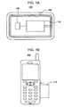
- Figs. 1A and 1B illustrate a mobile module containing a IC chip 110 incorporating a semiconductor integrated circuit of the present invention.
- the semiconductor integrated circuit can be incorporated as a single IC chip.
- the semiconductor integrated circuit may be divided into a plurality of IC chips distributed among a plurality of locations in the mobile module.
- the mobile module preferably permits the IC chip 110 to be housed therewithin, or to be attached thereonto.
- the mobile module is properly sized and weighted for users to carry easily.
- the mobile module may be any of the IC card 102 of Fig. 1A , a cellular phone 104 of Fig. 1B , a wristwatch, a personal digital assistant (PDA), a gaming machine, fancy goods such as a finger ring, etc.
- the IC card 102 as the mobile module is described below.
- the IC card 102 includes an antenna coil 106, a contact terminal 108, and an IC chip 110.
- the antenna coil 106 induces a voltage in response to a magnetic field generated by the external apparatus to operate the IC chip 110, and receives and transmits messages from and to the external apparatus.
- the contact terminal 108 put into contact with a contact terminal of the external apparatus receives power from the external apparatus to operate the IC chip 110, and receives and transmits messages from and to the external apparatus.
- the contact communication refers to a communication that is performed with the contact terminal of the mobile module placed in contact with the external apparatus.
- the contactless communication refers to a communication that is performed when the mobile module is not in contact with the external apparatus or when no electrical contact is established even if the mobile module and the external apparatus are physically in contact.
- the external apparatuses include a contact-type external apparatus and a contactless-type external apparatus.
- the contact-type external apparatuses include a credit card reader, a onboard unit of an electronic collection system (ETC) or an automated teller machine (ATM) of banks, for example.
- ETC electronic collection system
- ATM automated teller machine
- the contactless-type external apparatuses include an automatic ticket gate. Contactless communication between the contactless-type external apparatus and the mobile module is wirelessly performed. The contactless communication is performed within a short range of about 10 cm in accordance with the Near Field Communication (NFC) standard specifying a carrier radio frequency (RF) of 13.56 MHz at a data rate of 212 Kbps. Some external apparatuses have the contact and contactless communication capability.
- NFC Near Field Communication
- RF carrier radio frequency
- the IC chip 110 When powered by the antenna coil 106, the IC chip 110 performs contactless communication with the external apparatus. When powered from the contact terminal 108, the IC chip 110 performs contact communication with the external apparatus. The contact communication and the contactless communication will be discussed in more detail later.
- the mobile module containing the IC chip 110 has been roughly discussed.
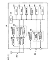
- the IC chip 110 is now described with reference to Fig. 2 .
- the IC chip 110 includes a rectifier 206, a first power generator 208, a demodulator 210, a modulator 212, a first receiver 214, a first transmitter 216, a second power generator 220, a second receiver 222, a second transmitter 224, a CPU (central processing unit) 228, a ROM (read-only memory) 230, a RAM (random-access memory) 232, an EEPROM (electrically erasable and programmable read-only memory) 234, an encryption engine 236, an RNG (random number generator) 238, a CRC (cyclic redundancy check) unit 240, etc.
- the rectifier 206 rectifies an alternating current voltage supplied from a contactless interface 202, such as the above-referenced coil, and supplies the rectified voltage to the first power generator 208.
- the first power generator 208 supplied with the voltage, generates a power source voltage to be used by the IC chip 110.
- the demodulator 210 demodulates a signal, received from the external apparatus via the contactless interface 202, into an electrical signal processable by the IC chip 110, and supplies the electrical signal to the first receiver 214.
- the modulator 212 modulates an electrical signal, to be transmitted from the IC chip 110 to the external apparatus via the contactless interface 202, into a signal transmittable in the contactless communication.
- the first receiver 214 and the first transmitter 216 function as a contactless-type communication unit 218 that communicates a contactless-type messages with the external apparatus in the contactless communication. The function of the contactless-type communication unit 218 will be described later.
- the second power generator 220 is powered by the external apparatus via a contact interface 204 such as the previously mentioned contact terminal, and generates a source power for use by the IC chip 110.
- the second receiver 222 and the second transmitter 224 function as a contact-type communication unit 226 that acquires contact-type messages from the external apparatus in the contact communication. The function of the contact-type communication unit 226 will be described later.
- the CPU 228 operates from the source power generated by one of the first power generator 208 and the second power generator 220 in the IC chip 110, and generally controls the entire IC chip 110.
- the ROM 230 is a non-volatile memory, and stores a variety applications, and an operating system (OS) serving as a platform.
- OS operating system
- the OS stored in the ROM 230 analyzes commands received by the IC chip 110 from the external apparatus, and performs a process in response to the command message. Also, the OS causes another application to perform the process, thereby generating a response message as a process result to be transmitted to the external apparatus.
- the OS Since the IC chip 110 of this embodiment of the present invention receives a contact-type command message, as one form of the contact-type message, supplied in the contact communication from the external apparatus, and a contactless-type command message, as one form of the contactless-type message, supplied in the contactless communication, the OS needs to understand the two type of command messages. Both the contact-type command message and the contactless-type command message have the same and common structure defined in Standard ISO/IEC7816-4. It is sufficient if the OS understands the common command, and a single OS is sufficient.
- the IC chip 110 is designed on the assumption that the contact-type command message and the contactless-type command message are different in structure.
- the contact-type command message has a structure that complies with the Standard ISO/IEC7816-4, but the contactless-type command message has a structure that does not comply with the Standard ISO/IEC7816-4.
- the contact-type command message may not comply with the Standard ISO/IEC7816-4, but the contactless-type command message may comply with the Standard ISO/IEC7816-4.
- both the contact-type command message and the contactless-type command message may not comply with the Standard ISO/IEC7816-4.
- the OS understanding the contact-type command message is referred to as a contact-type message processor and the other OS understanding the contactless-type command message is referred to as a contactless-type message processor.
- the RAM 232 stores the operating systems, and data temporarily used by each application.
- the EEPROM 234 is mainly used to store user data, but may store the applications and the OS, as well. A flash memory may be used instead of the EEPROM 234.
- the encryption engine 236 encrypts and decrypts data exchanged with the external apparatus.
- the RNG 238 generates a random number for use in an encryption key.
- the CRC unit 240 performs a cyclic redundancy check, namely, an error check, on data received from the external apparatus.
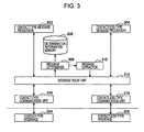
- the IC chip 110 has been discussed. A functional structure of the IC chip 110 is described below with reference to Fig. 3 .
- the IC chip 110 includes a contact-type message processor 302 for processing a contact-type message and a contactless-type message processor 304 for processing a contactless-type message.
- the contact-type message processor 302 is an OS that understands the contact-type command message, and performs a process responsive to the command message, or causes another application to perform the process to transmit a response message as the process result to the external apparatus.
- the contactless-type message processor 304 is an OS that understands the contactless-type command message, performs a process responsive to the command message or causes another application to perform the process to transmit a response message as the process result to the external apparatus.
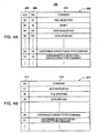
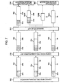
- the contact-type command message to be understood by the contact-type message processor 302 is described below with reference to a portion of (a) of Fig. 6 .
- the contact-type command message contains a header section 10a and a data section 10b.
- the header section 10a is an identifier identifying a contact-type message.
- the header section 10a is preferably placed at a fixed position within the contact-type command message, for example, at a zero byte of the contact-type message.
- a command representing the content of a process to be performed by the contact-type message processor 302 is contained in the header section 10a.
- the header section 10a contains CLA 602 representing the type of a command message as to whether the message complies with the ISO/IEC7816-4 Standard, INS 604 representing the content of a command for a data acquisition and file selection, P1606 and P2608 representing parameters used when the contact-type message processor 302 executes the command indicated by INS 604, and Lc 610 representing the length of the data section 10b.
- CLA 602 representing the type of a command message as to whether the message complies with the ISO/IEC7816-4 Standard
- INS 604 representing the content of a command for a data acquisition and file selection
- P1606 and P2608 representing parameters used when the contact-type message processor 302 executes the command indicated by INS 604
- Lc 610 representing the length of the data section 10b.
- the data section 10b stores data that is written in the contact-type message processor 302 in response to a data update command, and data used by the contact-type message processor 302 in the execution of commands.
- the contact-type command message may further store Le 612 designating a length of data that is acquired by the contact-type message processor 302 in the issue of a data acquisition command.
- Lc 610, and the data section 10b may be excluded from the contact-type command message.
- the contactless-type command message to be understood by the contactless-type message processor 304 is described below with reference to Fig. 8A .
- the contactless-type command message contains a header section 20a and a data section 20b.
- the header section 20a is an identifier identifying a contactless-type message.
- the header section 20a is preferably arranged at a fixed position within the contactless-type command message, for example, at a zero byte of the contactless-type message.
- the header section 20a contains a content of a command to be performed by the contactless-type message processor 304. More specifically, the header section 20a contains Sync 802 that is synchronization information required for the contactless communication with the external apparatus, Len 804 representing a length of data, and CD 806 representing a type and content of a command.
- the data section 20b stores data that is written onto the contactless-type message processor 304 in response to a data update command, and data that is used by the contactless-type message processor 304 for executing the command.
- the contactless-type command message may additionally include CRC 808 as an error detecting code to the data section 20b.
- Len 804 and the data section 20b may be excluded from the contactless-type command message.
- command messages are discussed for exemplary purposes only. Different structures may be applied to the contact-type command message and the contactless-type command message. Returning to Fig. 3 , the function and structure of IC chip 110 are described below.
- the contact-type communication unit 226 acquires contact-type messages in the contact communication from the external apparatus. More specifically, the contact-type communication unit 226 receives the contact-type command message via a contact-type interface 204 such as the contact terminal. The contact-type communication unit 226 also transmits a response message responsive to the contact-type command message via the contact-type interface 204.
- the contact-type command message received by the contact-type communication unit 226 from the external apparatus is understood and then processed by the contact-type message processor 302.
- a contactless-type command message can be contained in the above-described contact-type command message.
- the external apparatus embeds the contactless-type command message in the contact-type command message and transmits the command message in the contact communication to the IC chip 110 as a contact-type command message.
- an external apparatus having only a contact communication capability is still able to transmit to the IC chip 110 a command that can be transmitted by only an external apparatus having a contactless communication capability.
- a contactless-type command message 20 is contained in the contact-type command message shown in the portion (a) of Fig. 6 .
- the header section 10a and the data section 10b in the contact-type command message are followed by the contactless-type command message 20.
- the contact-type command message 10 of the portion (b) of Fig. 6 includes a command to be executed by the contact-type message processor 302 and data to be used by the contact-type message processor 302 in the execution of the command and the contactless-type command message 20. Even if the command to be executed by the contact-type message processor 302 and the contactless-type command message 20 are contained, the data section 10b may be sometimes contained.
- the header section 10a is followed by the contactless-type command message 20.
- the contact-type command message shown in the portion (c) of Fig. 6 does not contain a command to be executed by the contact-type message processor 302 and data to be used by the contact-type message processor 302 in the execution of the command.
- the contactless-type command message contained in the contact-type command message may have the same structure as the contactless-type command message shown in the portion (a) of Fig. 8 , may have a portion of the contactless-type command message, or may have the contactless-type command message in the compressed form thereof.
- the contact-type command message containing the contactless-type command message of the portions (b) and (c) of Fig. 6 is referred to as a virtual contact-type command message.
- the virtual contact-type command message can be communicated by the contact-type communication unit 226 because the virtual contact-type command message is generally in compliance with the format of the contact-type command message with the header section 10a identifying the contact-type command message arranged at a fixed position.
- the contactless-type communication unit 218 acquires the contactless-type command message from the external apparatus in the contactless communication. More specifically, the contactless-type communication unit 218 receives the contactless-type command message from the external apparatus via the contactless-type interface 202 such as the antenna coil. The contactless-type communication unit 218 transmits a response message responsive to the contactless-type command message to the external apparatus via the contactless-type interface 202.
- the contactless-type command message received by the contactless-type communication unit 218 from the external apparatus has the previously discussed structure that is understood and processed by the contactless-type message processor 304.
- the contactless-type command message having the above-referenced structure can contain the contact-type command message. More specifically, the external apparatus can embed the contact-type command message in the contactless-type command message, and transmit the command message to the IC chip 110 in the contactless communication as a contactless-type command message. In this way, an external apparatus having only the contactless communication capability still can transmit to the IC chip 110 a command that is to be transmitted by an external apparatus having the contact communication capability.
- a contact-type command message 10 is contained in the contactless-type command message shown in the portion (a) of Fig. 8 .
- the header section 20a and the data section 20b in the contactless-type command message are followed by the contact-type command message 10.
- the contactless-type command message shown in the portion (c) of Fig. 8 contains a command to be performed by the contactless-type message processor 304 and data to be used by the contactless-type message processor 304 in the execution of the command, and the contact-type command message 10. Even if the command to be performed by the contactless-type message processor 304 and the contact-type command message 10 are contained, the data section 20b may not be contained sometimes.
- the header section 20a in the contactless-type command message is followed by the contact-type command message 10.
- the contactless-type command message shown in the portion (c) of Fig. 8 contains the contact-type command message 10 but does not contain the command to be processed by the contactless-type message processor 304 and the data used in the execution of the command.
- the contact-type command message contained in the contactless-type command message may have the same structure as the contact-type command message discussed with reference to the portion (a) of Fig. 6 , or may have only a portion of the contact-type command message.
- the contactless-type command message contained in the contact-type command message shown in the portions (b) and (c) of Fig. 8 is referred to as a virtual contactless-type command message.
- the virtual contactless-type command message can be communicated by the contactless-type communication unit 218 because the virtual contactless-type command message is generally in compliance of the format of the contactless-type command message with the header section 20a identifying the contactless-type command message arranged at a fixed position.
- the message relay unit 312 acquires the contact-type command message from the contact-type communication unit 226, and supplies the acquired contact-type command message to the contact-type message processor 302.
- the message relay unit 312 acquires the contactless-type command message from the contactless-type communication unit 218, and supplies the acquired contactless-type command message to the contactless-type message processor 304. More specifically, the message relay unit 312 receives from the contact-type communication unit 226 the contact-type command message including the virtual contact-type command message, and supplies to the contact-type message processor 302 with only the contact-type command message understandable by the contact-type message processor 302.
- the message relay unit 312 receives the contactless-type command message including the virtual contactless-type command message, and supplies the contactless-type message processor 304 with only the contactless-type command message understandable by the contactless-type message processor 304.
- the message relay unit 312 supplies the contactless-type message processor 304 with the contactless-type command message contained in the virtual contact-type command message to cause the contactless-type message processor 304 to process the contactless-type command message.
- the message relay unit 312 supplies the contact-type message processor 302 with the contact-type command message contained in the virtual contactless-type command message to cause the contact-type message processor 302 to process the contact-type command message.
- the message determiner 308 determines whether the contactless-type command message to be supplied to the contactless-type message processor 304 is contained in the contact-type command message acquired from the contact-type communication unit 226. In other words, the message determiner 308 determines whether the contact-type command message is a virtual contact-type command message. To this end, the message determiner 308 references a predetermined portion of the contact-type command message, such as CLA 602 representing the type of the command and INS 604 representing the content of the command in the header section 10a in the contact-type command message.
- the message determiner 308 determines whether the contact-type command message to be supplied to the contact-type message processor 302 is contained in the contactless-type command message acquired by the message relay unit 312 from the contactless-type communication unit 218. In other words, the message determiner 308 determines whether the contactless-type command message is a virtual contactless-type command message. To this end, the message determiner 308 references a predetermined portion of the contactless-type command message, such as CD 806 representing the content of the command in the header section 20a in the contactless-type command message.
- Determination criteria can be stored beforehand in the ROM or EEPROM.
- a determination information memory 306 store such determination criteria, and is described below with reference to Figs. 4A and 4B .
- the determination information memory 306 includes a contact-type command message definition table 402 defining the contact-type command message and a contactless-type command message definition table 412 defining the contactless-type command message.
- the contact-type command message definition table 402 is described first.
- the contact-type command message definition table 402 includes a CLA column 406, an INS column 408, and a command column 410.
- the command column 410 stores the content of a command that is defined by a combination of data stored in the CLA column 406 and the INS column 408.
- the contact-type command message definition table 402 is defined as follows: the contact-type command message contains the contactless-type command message if the CLA column 406 has "XX", and a command to be processed by the contact-type message processor 302 is not contained if the CLA column 406 has "XX” and the INS column 408 has "FF".
- the contact-type command message definition table 402 is further defined as follows: the contactless-type command message and a command to be processed by the contact-type message processor 302 are contained if the CLA column 406 has "XX” and the INS column 408 has any setting other than "FF". Such a definition is used as the determination criteria in the determination of whether the contact-type command message is a virtual contact-type command message.
- the contactless-type command message definition table 412 is described below.
- the contactless-type command message definition table 412 contains a CD column 414 and a command column 416.
- the command column 416 stores a content of a command defined by data stored in the CD column 414.
- the contactless-type command message definition table 412 can use the definition of the command column 416 by the data in the CD column 414 as the determination criteria as to the determination of whether the contactless-type command message is a virtual contactless-type command message.
- the message determiner 308 feeds the command message to the message extractor 310.
- an identifier such as a message ID of the message is stored in a particular file, or a flag of the message is set so that the message extractor 310 can identify the command message.
- the message extractor 310 extracts the contactless-type command message from the contact-type command message supplied from the contact-type communication unit 226 to the message relay unit 312. More specifically, the message extractor 310 acquires the contactless-type command message contained in the virtual contactless-type command message, and supplies the contactless-type command message to the message relay unit 312.
- the contactless-type command message in its incomplete form is permitted. For example, when the contact-type command message containing the contactless-type command message is transmitted, Sync 802 as the synchronization information is not needed and thus not transmitted altogether.
- An incomplete contact-type command message may be supplied as is or a deficient portion may be added to make the complete contact-type command message before being supplied. In such a case, data of the deficient portion may be stored in the ROM 230.
- the message extractor 310 extracts the contact-type command message contained in the contactless-type command message supplied from the contactless-type communication unit 218 to the message relay unit 312. More specifically, the message extractor 310 acquires the contact-type command message contained in the virtual contactless-type command message and supplies contact-type command message to the message relay unit 312. If the contact-type command message is not in its complete form, a deficient portion may be added thereto before being supplied.
- the message relay unit 312 thus constructed acquires the contact-type command message from the contact-type communication unit 226, and causes the message determiner 308 to determine whether the contact-type command message is a virtual contact-type command message. If it is determined that the contact-type command message is not a virtual contact-type command message, the message relay unit 312 supplies the contact-type command message to the contact-type message processor 302 as is. If it is determined that the contact-type command message is a virtual contact-type command message, the message relay unit 312 causes the message extractor 310 to extract the contactless-type command message contained therewithin, and supplies the contactless-type command message to the contactless-type message processor 304.
- the message extractor 310 supplies the contact-type message processor 302 with the contact-type command message from which the message extractor 310 has extracted the contactless-type command message.
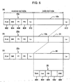
- the message relay unit 312 sorts the contact-type command messages containing the virtual contact-type command message between one for the contact-type message processor 302 and one for contactless-type message processor contactless-type message processor 304. Such a process of the message relay unit 312 is described below with reference to Fig. 5 .
- Reference numerals 502, 504, and 506 diagrammatically show contact-type command messages transmitted to the IC chip 110 from an external apparatus 500 that performs the contact communication.
- the first message 502 is composed of a header section 10a and a data section 10b in the contact-type command message.
- the second message 504 is composed the header section 10a, the data section 10b and a contactless-type command message 20.
- the second message 504 is a virtual contact-type command message.
- a third message 506, composed of a header section 10a and a contactless-type command message 20, is a virtual contact-type command message.
- the message relay unit 312 acquires one of the first message 502, the second message 504, and the third message 506, and performs a process responsive to the acquired message.
- the first message 502 is supplied to the contact-type message processor 302 as is.
- the second message 504 as the contactless-type command message contains a command to be processed by the contact-type message processor 302 and a contactless-type command message and is divided into a second message 504A as a command portion to be processed by the contact-type message processor 302, and a second message 504B as the contactless-type command message.
- the second message 504A and the second message 504B are respectively supplied to the contact-type message processor 302 and the contactless-type message processor 304.
- the third message 506 is the contact-type command message containing only the contactless-type command message.
- the contactless-type command message 20 is supplied to the contactless-type message processor 304 as a third message 506A.
- the message relay unit 312 acquires the contactless-type command message from the contactless-type communication unit 218, and causes the message determiner 308 to determine whether the contactless-type command message is a virtual contactless-type command message. If it is determined that the contactless-type command message is not a virtual contactless-type command message, the message relay unit 312 supplies the contactless-type command message to the contactless-type message processor 304. If it is determined that the contactless-type command message is a virtual contactless-type command message, the message relay unit 312 causes the message extractor 310 to extract the contact-type command message contained in the virtual contactless-type command message, and supplies the contact-type command message to the contact-type message processor 302.
- the message relay unit 312 supplies the contactless-type message processor 304 with the contactless-type command message from which the message extractor 310 has extracted the contact-type command message.
- the message relay unit 312 divides the contactless-type command message containing the virtual contactless-type command message between one for the contactless-type message processor 304 and one for the contact-type message processor 302. Such a process of the message relay unit 312 is described below with reference to Fig. 7 .
- Reference numerals 702, 704, and 706 diagrammatically show contactless-type command messages transmitted to the IC chip 110 from an external apparatus 700 that performs the contactless communication.
- the first message 702 is composed of the header section 20a and the data section 20b in the contactless-type command message.
- the second message 704, composed of the header section 20a, the data section 20b, and the contact-type command message 10, is a virtual contactless-type command message.
- the third message 706, composed of the header section 20a and the contact-type command message 10, is a virtual contactless-type command message.
- the message relay unit 312 acquires one of the first message 702, the second message 704, and the third message 706 from the contactless-type communication unit 218, and performs a process responsive to the acquired process.
- the message relay unit 312 supplies the first message 702 to the contactless-type message processor 304 as is.
- the second message 704 as the virtual contactless-type command message, composed of a command to be processed by the contactless-type message processor contactless-type message processor 304 and the contact-type command message, is divided between a second message 704A as the command to be processed by the contactless-type message processor 304 and a second message 704B as the contact-type command message.
- the second message 704A and the second message 704B are respectively supplied to the contactless-type message processor 304 and the contact-type message processor 302.
- the contact-type command message 10 is supplied to the contact-type message processor 302 as a third message 706A.
- the message relay unit 312 supplies command messages to the contact-type message processor 302 and the contactless-type message processor 304, receives response messages from each of the contact-type message processor 302 and the contactless-type message processor 304 in response to the command messages, and supplies the response messages to the contact-type communication unit 226 and the contactless-type communication unit 218 respectively.
- Such a process is described below with reference to Fig. 9 .
- the contact-type message processor 302 supplies the message relay unit 312 with the response message as a result of processing the contact-type command message.
- the contactless-type message processor 304 supplies the message relay unit 312 with the response message as a result of processing the contactless-type command message.
- Reference numerals 902, 904, 906, and 908 diagrammatically illustrate response messages.
- the message relay unit 312 converts the acquired messages into the messages in formats compatible with destinations.
- the first response 902 namely a response message to be transmitted to the contact-type external apparatus 500 in the contact communication
- the second response 904 is a response message to be transmitted to the external apparatus 700 in the contactless communication, and needs to be converted to the format in the contactless communication.
- a header section 20c indicating a contactless-type response message is added to the second response 904 before the second response 904 is supplied to the contactless-type communication unit 218.
- the third response 906 is a response message to be transmitted to the contact-type external apparatus 500.
- the message relay unit 312 adds a header section 10c indicating a contact-type response message to the third response 906, thereby converting the third response 906 to a format compatible with the response message in the contact communication.
- the resulting response message is supplied to the contact-type communication unit 226.
- the fourth response 908 is a response message to be transmitted to the contactless-type external apparatus 700 in the contactless communication, and is thus supplied to the contactless-type communication unit 218 as is.
- the function of the message relay unit 312 can be transferred to the responsibility of contact-type communication unit 226 or the contactless-type communication unit 218.
- each element of the IC chip 110 understands and processes each command message even if the contact-type command message and the contactless-type command message are different in structure.
- the message relay unit 312 processes the virtual contact-type command message and the virtual contactless-type command message as described above. Even when the external apparatus transmits a message in the contact communication to the IC chip 110, the IC chip 110 performs the same process that is applied to a message transmitted in the contactless communication. Even when the external apparatus transmits a message in the contactless communication to the IC chip 110, the IC chip 110 performs the same process that is applied to a message transmitted in the contact communication.
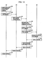
- a communication process flow of a virtual contact-type command message communicated between the contact-type external apparatus 500 and the IC chip 110 is described below with reference to Fig. 10 .
- step S102 the contact-type external apparatus 500 embeds a contactless-type command message into a contact-type command message. In other words, a virtual contact-type command message is generated.
- step S104 the virtual contact-type command message is transmitted to the contact-type communication unit 226 in the IC chip 110 in the contact communication.
- the contact-type communication unit 226 supplies the received virtual contact-type command message to the message relay unit 312 (step S106).
- the message relay unit 312 recognizes that the acquired message is the virtual contact-type command message containing the contactless-type command message (step S108).
- the contactless-type command message is extracted from the virtual contact-type command message (step S110), and the extracted contactless-type command message is supplied to the contactless-type message processor 304 (step S112).
- the contactless-type message processor 304 understands the acquired contactless-type command message and performs a process corresponding to the message (step S114), and supplies a response message as a result of the process to the message relay unit 312 (step S116). Since the destination of the response message acquired from the contactless-type message processor 304 is the contact-type external apparatus 500, the message relay unit 312 modifies the format of the message to that of the contact-type response message (step S118), and supplies the resulting response message to the contact-type communication unit 226 (step S120). The destination of the response message is determined by referencing an identifier of the external apparatus as the destination of the command message. The identifier of the external apparatus may be stored in association with a message identifier of the command message when the message relay unit 312 receives the command message.
- the contact-type communication unit 226 transmits the response message to the contact-type external apparatus 500 in the contact communication (step S122).
- the contact-type external apparatus 500 receives the response message (step S124), and the process ends.
- the communication process flow of the virtual contact-type command message communicated between the contact-type external apparatus 500 and the IC chip 110 has been discussed.
- a communication process flow of a virtual contactless-type command message communicated between the contactless-type external apparatus 700 and the IC chip 110 is described below with reference to Fig. 11 .
- step S202 the contactless-type external apparatus 700 embeds a contact-type command message into a contactless-type command message (step S202). In other words, a virtual contactless-type command message is generated.
- step S204 the virtual contactless-type command message is transmitted to the contactless-type communication unit 218 in the contactless communication.
- the contactless-type communication unit 218 supplies the received virtual contactless-type command message to the message relay unit 312 (step S206).
- the message relay unit 312 recognizes that the contactless-type command message contains the contact-type command message (step S208).
- the contact-type command message is extracted from the virtual contactless-type command message (step S210), and the extracted contact-type command message is supplied to the contact-type message processor 302 (step S212).
- the contact-type message processor 302 understands the acquired contact-type command message and performs a process corresponding to the message (step S214), and supplies a response message indicating the process result to the message relay unit 312 (step S216). Since the destination of the response message acquired from the contact-type message processor 302 is the contactless-type external apparatus 700, the message relay unit 312 changes the response message to the format of the contactless-type response message (step S218), and supplies the resulting response message to the contactless-type communication unit 218 (step S220).
- the contactless-type communication unit 218 transmits the response message to the contactless-type external apparatus 700 in the contactless communication (step S222).
- the contactless-type external apparatus 700 receives the response message (step S224). The process thus ends.
- the communication process flow of the virtual contactless-type command message communicated between the contactless-type external apparatus 700 and the IC chip 110 has been discussed.
- a process flow when the message relay unit 312 receives a contact-type command message from the contact-type communication unit 226 is described below with reference to Fig. 12 .
- step S302 the message relay unit 312 receives a contact-type command message from the contact-type communication unit 226.
- the message determiner 308 of the message relay unit 312 references command identification data present in a predetermined portion of the contact-type command message (more specifically, CLA 602 and INS 604) (step S304), and searches the determination information memory 306 for the corresponding command identification data (step S306).
- the message determiner 308 determines whether the contactless-type command message is contained in the contact-type command message acquired from the contact-type communication unit 226 (step S308). In other words, the message determiner 308 determines whether the contact-type command message is a virtual contact-type command message. If it is determined that the contact-type command message is not a virtual contact-type command message, the message relay unit 312 supplies the contact-type command message to the contact-type message processor 302 (step S314). The process thus ends.
- the message extractor 310 extracts the contactless-type command message contained in the contact-type command message (step S310).
- the message relay unit 312 supplies the contactless-type command message to the contactless-type message processor 304 (step S312). The process thus ends. If the virtual contact-type command message contains a command to be processed by the contact-type message processor 302, the message relay unit 312 supplies, to the contact-type message processor 302, the contact-type command message from which the contactless-type command message has already been extracted.
- the process of the message relay unit 312 that acquires the contact-type command message from the contact-type communication unit 226 has been discussed.
- a process of the message relay unit 312 that acquires a contactless-type command message from the contactless-type communication unit 218 is described below with reference to Fig. 13 .
- step S402 the message relay unit 312 acquires a contactless-type command message from the contactless-type communication unit 218.
- the message determiner 308 of the message relay unit 312 references command identification data present in a predetermined portion of the contactless-type command message (i.e., CD 806) (step S404), and searches the determination information memory 306 for the command identification data (step S406).
- the message determiner 308 determines whether a contact-type command message is contained in the contactless-type command message acquired from the contactless-type communication unit 218 (step S408). In other words, the contactless-type command message is a virtual contactless-type command message. If it is determined that the contact-type command message is not a virtual contactless-type command message, the message relay unit 312 supplies the contactless-type command message to the contactless-type message processor 304 (step S414), and the process ends.
- step S408 If it is determined in step S408 that the contact-type command message is a virtual contactless-type command message, the message extractor 310 extracts the contact-type command message contained in the contactless-type command message (step S410).
- the message relay unit 312 supplies the contact-type command message to the contact-type message processor 302 (step S412). The process thus ends. If a command to be processed by the contactless-type message processor 304 is contained in the virtual contactless-type command message, the message relay unit 312 supplies, to the contactless-type message processor 304, the contactless-type command message from which the contact-type command message has been extracted.
- the contact-type message processor and the contactless-type message processor are operating systems.
- the contact-type message processor and the contactless-type message processor may be application software programs as long as the programs can understand and process messages different in structure.
Landscapes
- Engineering & Computer Science (AREA)
- Physics & Mathematics (AREA)
- General Physics & Mathematics (AREA)
- Theoretical Computer Science (AREA)
- Health & Medical Sciences (AREA)
- Microelectronics & Electronic Packaging (AREA)
- Computer Hardware Design (AREA)
- Toxicology (AREA)
- Computer Networks & Wireless Communication (AREA)
- Computer Security & Cryptography (AREA)
- Electromagnetism (AREA)
- General Health & Medical Sciences (AREA)
- Artificial Intelligence (AREA)
- Computer Vision & Pattern Recognition (AREA)
- Mobile Radio Communication Systems (AREA)
- Telephone Function (AREA)
Claims (12)
- Integrierte Halbleiterschaltung (110), die Nachrichten mit einer externen Vorrichtung (500, 700) auf eine kontaktbehaftete Übertragungsweise und/oder eine kontaktlose Übertragungsweise überträgt, dadurch gekennzeichnet, dass die integrierte Halbleiterschaltung aufweist
eine Einheit (308, 310, 312) zum Bestimmen, ob eine Nachricht (20) der kontaktlosen Art in einer Nachricht (10, 504, 406) der kontaktbehafteten Art enthalten ist, welche auf die kontaktbehaftete Übertragungsweise von der externen Vorrichtung erlangt wurde, und zum Entnehmen der Nachricht der kontaktlosen Art aus der Nachricht der kontaktbehafteten Art, falls bestimmt wird, dass die Nachricht der kontaktlosen Art in der Nachricht der kontaktbehafteten Art enthalten ist; und
eine Einheit (308, 310, 312) zum Bestimmen, ob eine Nachricht (10) der kontaktbehafteten Art in einer Nachricht (20, 704, 706) der kontaktlosen Art enthalten ist, welche auf die kontaktlose Übertragungsweise von der externen Vorrichtung erlangt wurde, und zum Entnehmen der Nachricht der kontaktbehafteten Art aus der Nachricht der kontaktlosen Art, falls bestimmt wird, dass die Nachricht der kontaktbehafteten Art in der Nachricht der kontaktlosen Art enthalten ist. - Integrierte Halbleiterschaltung (110), die Nachrichten mit einer externen Vorrichtung (500, 700) auf eine kontaktbehaftete Übertragungsweise und/oder eine kontaktlose Übertragungsweise überträgt, wobei die integrierte Halbleiterschaltung aufweist
eine Übertragungseinheit (226) der kontaktbehafteten Art zum Erlangen einer Nachricht der kontaktbehafteten Art auf die kontaktbehaftete Übertragungsweise von der externen Vorrichtung;
eine Übertragungseinheit (218) der kontaktlosen Art zum Erlangen einer Nachricht der kontaktlosen Art auf die kontaktlose Übertragungsweise von der externen Vorrichtung;
einen Kontaktnachricht-Verarbeiter (302) zum Verarbeiten der Nachricht der kontaktbehafteten Art;
einen Kontaktlosnachricht-Verarbeiter (304) zum Verarbeiten der Nachricht der kontaktlosen Art; und
eine Nachricht-Weiterleitungseinheit (312) zum Erlangen der Nachricht der kontaktbehafteten Art von der Übertragungseinheit (226) der kontaktbehafteten Art, um die Nachricht der kontaktbehafteten Art an den Kontaktnachricht-Verarbeiter (302) zu liefern, und zum Erlangen der Nachricht der kontaktlosen Art von der Übertragungseinheit (218) der kontaktlosen Art, um die Nachricht der kontaktlosen Art an den Kontaktlosnachricht-Verarbeiter (304) zu liefern, dadurch gekennzeichnet, dass die Nachricht-Weiterleitungseinheit (312) einen Nachricht-Bestimmer (308) aufweist, zum Bestimmen, ob die an den Kontaktlosnachricht-Verarbeiter (304) zu liefernde Nachricht der kontaktlosen Art in der von der Übertragungseinheit (226) der kontaktbehafteten Art erlangten Nachricht der kontaktbehafteten Art enthalten ist. - Integrierte Halbleiterschaltung gemäß Anspruch 2, wobei der Nachricht-Bestimmer (308) basierend auf Daten eines vorbestimmten Teils der von der Übertragungseinheit (226) der kontaktbehafteten Art erlangten Nachricht der kontaktbehafteten Art bestimmt, ob die Nachricht der kontaktlosen Art in der Nachricht der kontaktbehafteten Art enthalten ist.
- Integrierte Halbleiterschaltung gemäß Anspruch 2 oder Anspruch 3, wobei die Nachricht-Weiterleitungseinheit (312) ferner einen Nachricht-Entnehmer (310) aufweist und
wobei der Nachricht-Entnehmer (310) die Nachricht der kontaktlosen Art entnimmt, die in der von der Übertragungseinheit (226) der kontaktbehafteten Art erlangten Nachricht der kontaktbehafteten Art enthalten ist. - Integrierte Halbleiterschaltung (110), die Nachrichten mit einer externen Vorrichtung (700) auf eine kontaktbehaftete Übertragungsweise und/oder eine kontaktlose Übertragungsweise überträgt, wobei die integrierte Halbleiterschaltung aufweist
eine Übertragungseinheit (226) der kontaktbehafteten Art zum Erlangen einer Nachricht der kontaktbehafteten Art auf die kontaktbehaftete Übertragungsweise von der externen Vorrichtung;
eine Übertragungseinheit (218) der kontaktlosen Art zum Erlangen einer Nachricht der Art auf die kontaktlosen Übertragungsweise von der externen Vorrichtung;
einen Kontaktnachricht-Verarbeiter (302) zum Verarbeiten der Nachricht der kontaktbehafteten Art;
einen Kontaktlosnachricht-Verarbeiter (304) zum Verarbeiten der Nachrichten der kontaktlosen Art;
eine Nachricht-Weiterleitungseinheit (312) zum Erlangen der Nachricht der kontaktbehafteten Art von der Übertragungseinheit (226) der kontaktbehafteten Art, um die Nachricht der kontaktbehafteten Art an den Kantaktnachricht-Verarbeiter (302) Art zu liefern, und zum Erlangen der Nachricht der kontaktlosen Art von der Übertragungseinheit (218) der kontaktlosen Art, um die Nachricht der kontaktlosen Art an den Kontaktlosnachricht-Verarbeiter (304) zu liefern, dadurch gekennzeichnet, dass die Nachricht-Weiterleitungseinheit (312) einen Nachricht-Bestimmer (308) aufweist, zum Bestimmen, ob die an den Kontaktnachricht-Verarbeiter (302) zu liefernde Nachricht der kontaktbehafteten Art in der von der Übertragungseinheit (218) der kontaktlosen Art erlangten Nachricht der kontaktlosen Art enthalten ist. - Integrierte Halbleiterschaltung gemäß Anspruch 5, wobei der Nachricht-Bestimmer (308) basierend auf Daten eines vorbestimmten Teils der von der Übertragungseinheit (218) der kontaktlosen Art erlangten Nachricht der kontaktlosen Art bestimmt, ob die Nachricht der kontaktbehafteten Art in der Nachricht der kontaktlosen Art enthalten ist.
- Integrierte Halbleiterschaltung gemäß Anspruch 5 oder Anspruch 6, wobei die Nachricht-Weiterleitungseinheit (312) ferner einen Naehricht-Entnehmer (310) aufweist und
wobei der Nachricht-Entnehmer (310) die Nachricht der kontaktbehafteten Art entnimmt, die in der von der Übertragungseinheit (218) der kontaktlosen Art erlangten Nachricht der kontaktlosen Art enthalten ist. - Integrierte Halbleiterschaltung gemäß Anspruch 2 oder Anspruch 5,
wobei der Nachricht-Bestimmer (308) bestimmt, ob die an den Kontaktlosnachricht-Verarbeiter (304) zu liefernde Nachricht der kontaktlosen Art in der von der Übertragungseinheit (226) der Art erlangten Nachrichtder kontaktbehafteten Art enthalten ist, und bestimmt, ob die an den Kontaktnachricht-Verarbeiter (302) zu liefernde Nachricht der kontaktbehafteten Art in der von der Übertragungseinheit (218) der kontaktlosen Art erlangten Nachricht der kontaktlosen Art enthalten ist. - Integrierte Halbleiterschaltung gemäß Anspruch 8, wobei die Nachricht-Weiterleitungseinheit (312) ferner einen Nachricht-Entnehmer (310) aufweist und
wobei der Nachricht-Entnehmer die Nachricht der kontaktlosen Art entnimmt, die in der von der Übertragungseinheit (226) der kontaktbehafteten Art erlangten Nachricht der kontaktbehafteten Art enthalten ist, während sie die Nachricht der kontaktbehafteten Art entnimmt, die in der von der Übertragungseinheit (218) der kontaktlosen Art erlangten Nachricht der kontaktlosen Art enthalten ist. - Tragbares Modul, das eine integrierte Halbleiterschaltung (110) gemäß einem der Ansprüche 1 bis 9 aufweist.
- Nachrichtenübertragungsverfahren, das ausgeführt wird zwischen einem tragbaren Modul (102, 104), das fähig ist Nachrichten mit einer externen Vorrichtung auf eine kontaktbehaftete Übertragungsweise und/oder eine kontaktlose Übertragungsweise zu übertragen, und einer externen Vorrichtung (500) der kontaktbehafteten Art, welche Nachrichten mit dem tragbaren Modul auf eine kontaktbehaftete Übertragungsweise überträgt, dadurch gekennzeichnet, dass das Nachrichtenübertragungsverfahren die Schritte aufweist
Einbetten (S 102) einer Nachricht der kontaktlosen Art in eine Nachricht der kontaktbehafteten Art, die an das tragbare Modul auf die kontaktbehaftete Übertragungsweise zu übertragen ist;
Übertragen (S104) der Nachricht der kontaktbehafteten Art, welche die Nachricht der kontaktlosen Art enthält, an das tragbare Modul;
Empfangen der Nachricht der kontaktbehafteten Art, welche die Nachricht der kontaktlosen Art enthält;
Bestimmen (S108), ob die Nachricht der kontaktlosen Art in der empfangenen Nachricht der kontaktbehafteten Art enthalten ist; und
Entnahmen (S110) Nachricht der kontaktlosen Art, die in der empfangenen Nachricht der kontaktbehafteten Art enthalten ist. - Nachrichtenübertragungsverfahren, das ausgeführt wird zwischen einem tragbaren Modul (102, 104), das fähig ist Nachrichten mit einer externen Vorrichtung auf eine kontaktbehaftete Übertragungsweise und/oder eine kontaktlose Übertragungsweise zu übertragen, und einer externen Vorrichtung (700) der kontaktlosen Art, welche Nachrichten mit dem tragbaren Modul auf eine kontaktlose Übertragungsweise überträgt, dadurch gekennzeichnet, dass das Nachrichtenübertragungsverfahren die Schritte aufweist
Einbetten (S202) einer Nachricht der kontaktbehafteten Art in eine Nachricht der kontaktlosen Art, die an das tragbare Modul auf die kontaktlose Übertragungsweise zu übertragen ist;
Übertragen (S204) der Nachricht der kontaktlosen Art, welche die Nachricht der kontaktbehafteten Art enthält, an das tragbare Modul;
Empfangen der Nachricht der kontaktlosen Art, welche die Nachricht der kontaktbehafteten Art enthält;
Bestimmen (S208), ob die Nachricht der kontaktbehafteten Art in der empfangenen Nachricht der kontaktlosen Art enthalten ist; und
Entnehmen (S210) der Nachricht der kontaktbehafteten Art, die in der empfangenen Nachricht der kontaktlosen Art enthalten ist.
Applications Claiming Priority (2)
| Application Number | Priority Date | Filing Date | Title |
|---|---|---|---|
| JP2004047918A JP4617683B2 (ja) | 2004-02-24 | 2004-02-24 | 半導体集積回路,携帯モジュールおよびメッセージ通信方法。 |
| JP2004047918 | 2004-02-24 |
Publications (3)
| Publication Number | Publication Date |
|---|---|
| EP1569164A2 EP1569164A2 (de) | 2005-08-31 |
| EP1569164A3 EP1569164A3 (de) | 2008-05-14 |
| EP1569164B1 true EP1569164B1 (de) | 2010-12-29 |
Family
ID=34747438
Family Applications (1)
| Application Number | Title | Priority Date | Filing Date |
|---|---|---|---|
| EP05290409A Expired - Lifetime EP1569164B1 (de) | 2004-02-24 | 2005-02-23 | Integrierte Halbleiterschaltung, tragbares Modul und Nachrichtenübertragungsverfahren |
Country Status (6)
| Country | Link |
|---|---|
| US (1) | US7365642B2 (de) |
| EP (1) | EP1569164B1 (de) |
| JP (1) | JP4617683B2 (de) |
| CN (1) | CN100386777C (de) |
| DE (1) | DE602005025557D1 (de) |
| SG (1) | SG114710A1 (de) |
Families Citing this family (41)
| Publication number | Priority date | Publication date | Assignee | Title |
|---|---|---|---|---|
| US7292828B1 (en) * | 2002-09-05 | 2007-11-06 | Case Western Reserve University | Miniaturized multichannel transmitter and wireless telemetry system |
| EP1725977B1 (de) | 2004-03-19 | 2009-04-15 | Nokia Corporation | Detektorlogik und funkidentifikationseinrichtung und verfahren zur verbesserung des terminal-betriebs |
| KR100664691B1 (ko) * | 2005-02-28 | 2007-01-04 | 김갑식 | 외부전원을 공급받아 작동되는 디지탈 장치 및 그의 제어방법 |
| KR100728637B1 (ko) * | 2005-09-08 | 2007-06-15 | (주)한창시스템 | 플러그-인 형태로 여러 가지 보안 모듈들을 지원하는 보안nfc 통신 장치 및 방법 |
| JP2007087120A (ja) * | 2005-09-22 | 2007-04-05 | Dainippon Printing Co Ltd | 複数のosを実装したicカード、および、発行委任方法 |
| JP4506658B2 (ja) * | 2005-11-30 | 2010-07-21 | ソニー株式会社 | 無線通信システム,通信装置,設定情報提供方法,設定情報取得方法,およびコンピュータプログラム |
| US8352323B2 (en) * | 2007-11-30 | 2013-01-08 | Blaze Mobile, Inc. | Conducting an online payment transaction using an NFC enabled mobile communication device |
| US20070218837A1 (en) * | 2006-03-14 | 2007-09-20 | Sony Ericsson Mobile Communications Ab | Data communication in an electronic device |
| DE102006021087A1 (de) * | 2006-05-05 | 2007-11-08 | Giesecke & Devrient Gmbh | Simultaner Schnittstellenbetrieb |
| JP2008059246A (ja) * | 2006-08-31 | 2008-03-13 | Yoshikawa Rf System Kk | データキャリア及びデータキャリアシステム |
| US8047431B2 (en) * | 2006-09-15 | 2011-11-01 | Panasonic Corporation | Portable terminal, noncontact IC module, reader/writer and information distribution method |
| WO2008070854A1 (en) * | 2006-12-07 | 2008-06-12 | Neology, Inc. | Systems and methods for incorporating an rfid circuit into a memory device |
| US8117445B2 (en) * | 2006-12-20 | 2012-02-14 | Spansion Llc | Near field communication, security and non-volatile memory integrated sub-system for embedded portable applications |
| US8190885B2 (en) * | 2006-12-21 | 2012-05-29 | Spansion Llc | Non-volatile memory sub-system integrated with security for storing near field transactions |
| US8078226B2 (en) * | 2007-08-29 | 2011-12-13 | Mxtran, Inc. | Multiple interface card in a mobile phone |
| JP2010039913A (ja) * | 2008-08-07 | 2010-02-18 | Sony Corp | 通信装置、通信方法、及びプログラム |
| JP4888742B2 (ja) * | 2009-02-25 | 2012-02-29 | ソニー株式会社 | 情報処理装置および方法、並びにプログラム |
| JP5310348B2 (ja) * | 2009-07-17 | 2013-10-09 | ソニー株式会社 | 受信装置、受信方法、プログラム、及び送信装置 |
| US9367331B2 (en) | 2009-07-20 | 2016-06-14 | Google Technology Holdings LLC | Multi-environment operating system |
| US9389877B2 (en) | 2009-07-20 | 2016-07-12 | Google Technology Holdings LLC | Multi-environment operating system |
| US9372711B2 (en) | 2009-07-20 | 2016-06-21 | Google Technology Holdings LLC | System and method for initiating a multi-environment operating system |
| GB2474060A (en) * | 2009-10-05 | 2011-04-06 | Sero Solutions Ltd | An antenna suitable for use with the Near Field Communication standard is fitted to a human finger |
| JP2011118837A (ja) | 2009-12-07 | 2011-06-16 | Sony Corp | 情報処理装置、情報処理方法およびプログラム |
| JP2011210140A (ja) * | 2010-03-30 | 2011-10-20 | Sony Corp | 通信装置、通信方法、情報処理装置、情報処理方法、プログラム、および情報処理システム |
| US9575777B2 (en) | 2011-03-08 | 2017-02-21 | Sony Corporation | Information processing device for performing contactless communication with an external device using multiple communication standards |
| US9354900B2 (en) | 2011-04-28 | 2016-05-31 | Google Technology Holdings LLC | Method and apparatus for presenting a window in a system having two operating system environments |
| US8879985B2 (en) * | 2011-06-28 | 2014-11-04 | Broadcom Corporation | Memory arbitrator for electronics communications devices |
| US9544759B2 (en) | 2011-11-01 | 2017-01-10 | Google Inc. | Systems, methods, and computer program products for managing states |
| KR101515768B1 (ko) | 2011-11-01 | 2015-04-28 | 제이브이엘 벤쳐스, 엘엘씨 | 보안 요소를 관리하기 위한 시스템, 방법 및 컴퓨터 프로그램 제품 |
| US20130293573A1 (en) | 2012-05-02 | 2013-11-07 | Motorola Mobility, Inc. | Method and Apparatus for Displaying Active Operating System Environment Data with a Plurality of Concurrent Operating System Environments |
| US9342325B2 (en) | 2012-05-17 | 2016-05-17 | Google Technology Holdings LLC | Synchronizing launch-configuration information between first and second application environments that are operable on a multi-modal device |
| SG11201407716UA (en) | 2012-05-31 | 2015-03-30 | Sony Corp | Information processing device, information processing method, and program |
| US8676709B2 (en) | 2012-07-31 | 2014-03-18 | Google Inc. | Merchant category codes in a proxy card transaction |
| WO2014047069A1 (en) | 2012-09-18 | 2014-03-27 | Jvl Ventures, Llc | Systems, methods, and computer program products for interfacing multiple service provider trusted service managers and secure elements |
| TWM446938U (zh) * | 2012-09-28 | 2013-02-11 | Smart Approach Co Ltd | 無線射頻識別模組 |
| US9124304B2 (en) | 2012-10-17 | 2015-09-01 | Qualcomm Incorporated | Methods and apparatus for reducing overhead for NFC data exchange protocol messages |
| WO2015037187A1 (ja) * | 2013-09-11 | 2015-03-19 | パナソニックIpマネジメント株式会社 | 通信デバイス及び通信システム |
| US20150174465A1 (en) * | 2013-12-20 | 2015-06-25 | Kiwi Golf, Llc | Golf stroke information |
| KR102048016B1 (ko) * | 2013-12-30 | 2019-11-22 | 삼성전자주식회사 | Nfc 단말기 및 이를 포함하는 통신장치 |
| WO2016063659A1 (ja) * | 2014-10-22 | 2016-04-28 | ソニー株式会社 | 情報処理装置、情報処理方法、およびプログラム |
| DE102017223687A1 (de) * | 2017-12-22 | 2019-06-27 | Bundesdruckerei Gmbh | Prozessorchipkarte und Verfahren zum Betrieb einer Prozessorchipkarte |
Family Cites Families (22)
| Publication number | Priority date | Publication date | Assignee | Title |
|---|---|---|---|---|
| DE4406704C1 (de) * | 1994-03-02 | 1995-07-20 | Angewandte Digital Elektronik | Chipkarte |
| ATE272873T1 (de) * | 1995-06-02 | 2004-08-15 | Koninkl Philips Electronics Nv | Chipkarte |
| JP3360002B2 (ja) | 1996-03-14 | 2002-12-24 | 沖電気工業株式会社 | 接触式・非接触式兼用icカード及び接触式・非接触式兼用icカードリーダライタ |
| IL119943A (en) * | 1996-12-31 | 2000-11-21 | On Track Innovations Ltd | Contact/contactless data transaction card |
| JPH10322415A (ja) * | 1997-05-16 | 1998-12-04 | Nec Shizuoka Ltd | モデム用アダプタ及びモデムシステム |
| CN1122936C (zh) | 1997-10-22 | 2003-10-01 | 皇家菲利浦电子有限公司 | 双模式数据运载器及用于这一具有简化的数据传送装置的数据运载器的电路 |
| IL122841A0 (en) | 1997-12-31 | 1998-08-16 | On Track Innovations Ltd | Smart card for effecting data transfer using multiple protocols |
| DE69933963T2 (de) | 1998-03-24 | 2007-09-20 | Kabushiki Kaisha Toshiba | IC Karte mit kontaktbehafteten und kontaktlosen Schnittstellen |
| WO1999059098A1 (de) * | 1998-05-07 | 1999-11-18 | Orga Kartensysteme Gmbh | Verfahren zur steuerung der kommunikation zwischen einer mikroprozessor-chipkarte und einem kontaktbehaftet arbeitenden terminal oder einem kontaktlos arbeitenden terminal |
| FR2783069B1 (fr) | 1998-09-04 | 2003-01-24 | Inside Technologies | Lecteur de carte a puce |
| JP2000113148A (ja) * | 1998-10-08 | 2000-04-21 | Motorola Japan Ltd | コンビネーションカード |
| JP4209512B2 (ja) * | 1998-10-20 | 2009-01-14 | 大日本印刷株式会社 | Icカード |
| JP2000172814A (ja) * | 1998-12-02 | 2000-06-23 | Toppan Printing Co Ltd | 複合icモジュール及び複合icカード |
| JP2001251321A (ja) * | 2000-03-08 | 2001-09-14 | Ricoh Co Ltd | 遠隔操作システム及び遠隔操作方法 |
| US6899277B2 (en) | 2001-05-17 | 2005-05-31 | Matsushita Electric Industrial Co., Ltd. | IC card and electronic devices |
| JP2002351623A (ja) * | 2001-05-23 | 2002-12-06 | Fujitsu Ltd | 携帯電話機 |
| JP3683515B2 (ja) * | 2001-07-24 | 2005-08-17 | 株式会社エヌ・ティ・ティ・ドコモ | 輻輳抑制コマンド投入システム、コマンド多重化装置及び輻輳抑制コマンド投入方法 |
| JP2003132313A (ja) | 2001-10-24 | 2003-05-09 | Toshiba Corp | コンビカード用lsi、コンビカード及びコンビカードの使用方法 |
| JP3863011B2 (ja) | 2001-11-29 | 2006-12-27 | シャープ株式会社 | コンビネーション型icカード、及びその制御方法、並びにそのシステムプログラム |
| JP2003256751A (ja) | 2002-03-01 | 2003-09-12 | Nippon Telegr & Teleph Corp <Ntt> | モバイルペイメント携帯機器、カードホルダ及びシステム並びにicカード使い分け支払方法 |
| JP2003281484A (ja) * | 2002-03-22 | 2003-10-03 | Toppan Printing Co Ltd | Icカード |
| JP4558259B2 (ja) * | 2002-05-23 | 2010-10-06 | シャープ株式会社 | コンビネーション型icカード |
-
2004
- 2004-02-24 JP JP2004047918A patent/JP4617683B2/ja not_active Expired - Lifetime
-
2005
- 2005-02-08 SG SG200500715A patent/SG114710A1/en unknown
- 2005-02-08 US US11/052,075 patent/US7365642B2/en not_active Expired - Lifetime
- 2005-02-23 DE DE602005025557T patent/DE602005025557D1/de not_active Expired - Lifetime
- 2005-02-23 EP EP05290409A patent/EP1569164B1/de not_active Expired - Lifetime
- 2005-02-24 CN CNB2005100655165A patent/CN100386777C/zh not_active Expired - Fee Related
Also Published As
| Publication number | Publication date |
|---|---|
| CN1661630A (zh) | 2005-08-31 |
| DE602005025557D1 (de) | 2011-02-10 |
| JP2005242445A (ja) | 2005-09-08 |
| US20050191968A1 (en) | 2005-09-01 |
| CN100386777C (zh) | 2008-05-07 |
| SG114710A1 (en) | 2005-09-28 |
| EP1569164A3 (de) | 2008-05-14 |
| EP1569164A2 (de) | 2005-08-31 |
| US7365642B2 (en) | 2008-04-29 |
| HK1082831A1 (zh) | 2006-06-16 |
| JP4617683B2 (ja) | 2011-01-26 |
Similar Documents
| Publication | Publication Date | Title |
|---|---|---|
| EP1569164B1 (de) | Integrierte Halbleiterschaltung, tragbares Modul und Nachrichtenübertragungsverfahren | |
| CN100448174C (zh) | 包括rfid标签的移动终端电路及使用该移动终端电路的无线识别方法 | |
| EP1528768A2 (de) | Mobiles Kommunikationsterminal mit RFID-Funktion und RFID-Programmierungsverfahren | |
| US8561900B2 (en) | Data transfer system, data acquisition device, data acquisition method, data accumulation device, data transmission method, and program for the same | |
| JP6516133B2 (ja) | 通信デバイス及び通信システム | |
| US10032105B2 (en) | IC card, portable terminal, and portable electronic apparatus | |
| JP4692807B2 (ja) | 接触式データ通信装置、送受信装置、および送受信方法 | |
| US10931331B2 (en) | Communication device and method | |
| KR20050074948A (ko) | 비접촉 ic카드 | |
| US20220350975A1 (en) | Ic card, ic card processing system, and computer-readable storage medium | |
| KR101552393B1 (ko) | Ic 카드, 휴대 가능 전자 장치 및 리더 라이터 | |
| KR101621127B1 (ko) | Ic 카드, 휴대 가능 전자 장치 및 리더 라이터 | |
| JP4426820B2 (ja) | 非接触icカード | |
| HK1082831B (en) | Semiconductor integrated circuit, mobile module, and message communication method | |
| KR20060120616A (ko) | 시스템 기능을 실행하는 시스템 및 접촉-제한 특성 블록의생성 방법 | |
| JP2012194916A (ja) | 携帯可能電子装置、携帯可能電子装置の処理装置、及び携帯可能電子装置の処理システム |
Legal Events
| Date | Code | Title | Description |
|---|---|---|---|
| PUAI | Public reference made under article 153(3) epc to a published international application that has entered the european phase |
Free format text: ORIGINAL CODE: 0009012 |
|
| AK | Designated contracting states |
Kind code of ref document: A2 Designated state(s): AT BE BG CH CY CZ DE DK EE ES FI FR GB GR HU IE IS IT LI LT LU MC NL PL PT RO SE SI SK TR |
|
| AX | Request for extension of the european patent |
Extension state: AL BA HR LV MK YU |
|
| PUAL | Search report despatched |
Free format text: ORIGINAL CODE: 0009013 |
|
| AK | Designated contracting states |
Kind code of ref document: A3 Designated state(s): AT BE BG CH CY CZ DE DK EE ES FI FR GB GR HU IE IS IT LI LT LU MC NL PL PT RO SE SI SK TR |
|
| AX | Request for extension of the european patent |
Extension state: AL BA HR LV MK YU |
|
| RIC1 | Information provided on ipc code assigned before grant |
Ipc: G06K 19/07 20060101AFI20050630BHEP Ipc: G06K 7/00 20060101ALI20080408BHEP |
|
| 17P | Request for examination filed |
Effective date: 20081106 |
|
| 17Q | First examination report despatched |
Effective date: 20081219 |
|
| AKX | Designation fees paid |
Designated state(s): DE FR GB |
|
| GRAP | Despatch of communication of intention to grant a patent |
Free format text: ORIGINAL CODE: EPIDOSNIGR1 |
|
| GRAS | Grant fee paid |
Free format text: ORIGINAL CODE: EPIDOSNIGR3 |
|
| GRAA | (expected) grant |
Free format text: ORIGINAL CODE: 0009210 |
|
| AK | Designated contracting states |
Kind code of ref document: B1 Designated state(s): DE FR GB |
|
| REG | Reference to a national code |
Ref country code: GB Ref legal event code: FG4D |
|
| REF | Corresponds to: |
Ref document number: 602005025557 Country of ref document: DE Date of ref document: 20110210 Kind code of ref document: P |
|
| REG | Reference to a national code |
Ref country code: DE Ref legal event code: R096 Ref document number: 602005025557 Country of ref document: DE Effective date: 20110210 |
|
| PLBE | No opposition filed within time limit |
Free format text: ORIGINAL CODE: 0009261 |
|
| STAA | Information on the status of an ep patent application or granted ep patent |
Free format text: STATUS: NO OPPOSITION FILED WITHIN TIME LIMIT |
|
| 26N | No opposition filed |
Effective date: 20110930 |
|
| REG | Reference to a national code |
Ref country code: DE Ref legal event code: R097 Ref document number: 602005025557 Country of ref document: DE Effective date: 20110930 |
|
| REG | Reference to a national code |
Ref country code: GB Ref legal event code: 746 Effective date: 20120703 |
|
| REG | Reference to a national code |
Ref country code: DE Ref legal event code: R084 Ref document number: 602005025557 Country of ref document: DE Effective date: 20120614 |
|
| REG | Reference to a national code |
Ref country code: FR Ref legal event code: PLFP Year of fee payment: 12 |
|
| REG | Reference to a national code |
Ref country code: FR Ref legal event code: PLFP Year of fee payment: 13 |
|
| REG | Reference to a national code |
Ref country code: FR Ref legal event code: PLFP Year of fee payment: 14 |
|
| PGFP | Annual fee paid to national office [announced via postgrant information from national office to epo] |
Ref country code: FR Payment date: 20230119 Year of fee payment: 19 |
|
| PGFP | Annual fee paid to national office [announced via postgrant information from national office to epo] |
Ref country code: GB Payment date: 20230120 Year of fee payment: 19 Ref country code: DE Payment date: 20230119 Year of fee payment: 19 |
|
| P01 | Opt-out of the competence of the unified patent court (upc) registered |
Effective date: 20230527 |
|
| REG | Reference to a national code |
Ref country code: DE Ref legal event code: R119 Ref document number: 602005025557 Country of ref document: DE |
|
| GBPC | Gb: european patent ceased through non-payment of renewal fee |
Effective date: 20240223 |
|
| PG25 | Lapsed in a contracting state [announced via postgrant information from national office to epo] |
Ref country code: DE Free format text: LAPSE BECAUSE OF NON-PAYMENT OF DUE FEES Effective date: 20240903 |
|
| PG25 | Lapsed in a contracting state [announced via postgrant information from national office to epo] |
Ref country code: GB Free format text: LAPSE BECAUSE OF NON-PAYMENT OF DUE FEES Effective date: 20240223 |
|
| PG25 | Lapsed in a contracting state [announced via postgrant information from national office to epo] |
Ref country code: FR Free format text: LAPSE BECAUSE OF NON-PAYMENT OF DUE FEES Effective date: 20240229 |
|
| PG25 | Lapsed in a contracting state [announced via postgrant information from national office to epo] |
Ref country code: GB Free format text: LAPSE BECAUSE OF NON-PAYMENT OF DUE FEES Effective date: 20240223 Ref country code: FR Free format text: LAPSE BECAUSE OF NON-PAYMENT OF DUE FEES Effective date: 20240229 Ref country code: DE Free format text: LAPSE BECAUSE OF NON-PAYMENT OF DUE FEES Effective date: 20240903 |