EP1569028B1 - Dispositif d'installation de lunettes et monture de lunettes - Google Patents
Dispositif d'installation de lunettes et monture de lunettes Download PDFInfo
- Publication number
- EP1569028B1 EP1569028B1 EP04723020A EP04723020A EP1569028B1 EP 1569028 B1 EP1569028 B1 EP 1569028B1 EP 04723020 A EP04723020 A EP 04723020A EP 04723020 A EP04723020 A EP 04723020A EP 1569028 B1 EP1569028 B1 EP 1569028B1
- Authority
- EP
- European Patent Office
- Prior art keywords
- temple
- ear
- contacting portion
- ear contacting
- attached
- Prior art date
- Legal status (The legal status is an assumption and is not a legal conclusion. Google has not performed a legal analysis and makes no representation as to the accuracy of the status listed.)
- Expired - Lifetime
Links
Images


Classifications
-
- G—PHYSICS
- G02—OPTICS
- G02C—SPECTACLES; SUNGLASSES OR GOGGLES INSOFAR AS THEY HAVE THE SAME FEATURES AS SPECTACLES; CONTACT LENSES
- G02C5/00—Constructions of non-optical parts
- G02C5/14—Side-members
- G02C5/143—Side-members having special ear pieces
-
- G—PHYSICS
- G02—OPTICS
- G02C—SPECTACLES; SUNGLASSES OR GOGGLES INSOFAR AS THEY HAVE THE SAME FEATURES AS SPECTACLES; CONTACT LENSES
- G02C11/00—Non-optical adjuncts; Attachment thereof
-
- G—PHYSICS
- G02—OPTICS
- G02C—SPECTACLES; SUNGLASSES OR GOGGLES INSOFAR AS THEY HAVE THE SAME FEATURES AS SPECTACLES; CONTACT LENSES
- G02C3/00—Special supporting arrangements for lens assemblies or monocles
- G02C3/003—Arrangements for fitting and securing to the head in the position of use
Definitions
- the present invention relates to an optical frame attachment attachable to an optical frame, and to an optical frame. More particularly, the present invention relates to an optical frame attachment and an optical frame for preventing glasses from slipping down.
- a present commonly used optical frame comprises a front frame which holds lenses and to which nose pads are attached, and a pair of temples each of which extends backward from both ends of the front frame.
- a rear portion of the temple is bent downward; thus, functioning as an ear pad member. Glasses are worn by hooking the rear portion of the temple at the back of an ear (between ear and head).
- a part (rear portion) of the temple constitutes the ear pad member, when a user performs various movements, the rear portion of the temple easily slips up, so that the glasses are easily slipped down.
- FIG. 6 is a schematic side view of a conventional optical frame.
- a front frame 71 starts to slip down in a state where the glasses are worn (state A)
- a rear portion of a temple 72 starts to slip up, thereby moving a ear pad member 73 upward.
- the ear pad member 73 When the ear pad member 73 starts to move upward, the ear pad member 73 starts to rotate in a counter-clockwise direction with the use of a shaft 70 of an ear pad member attaching portion 72a of the temple 72 as a rotational center.
- a force in a front end of the ear pad member 73 pressing against the back of the ear becomes greater and, as a result, the relative movement between the ear pad member 73 and the back of the ear is hindered, so that the rear portion of the temple 13 is prevented from slipping up. Glasses are thereby prevented from slipping down.
- the conventional optical frame has the following problems.
- the optical frame attached with the ear pad member 73 as in the conventional optical frame is a special optical frame and does not have versatility.
- the optical frame since the optical frame has presently established a status as an accessory or as part of fashion, the optical frame is often changed depending on the mood of the day.
- To have all the optical frames like the conventional optical frame increases their manufacturing cost, thus increasing the unit price of the optical frame. Further, it is considered that the degree of freedom of design of the optical frame is limited.
- the user has a plurality of optical frames, it is expensive to have all the optical frames like the above optical frame, thus narrowing the range of choice of the optical frame.
- the temple 72 is lifted upward when the user takes off the glasses (state B)
- the hair tends to get into a space between the temple 72 and the front end of the ear pad member 73 from an x direction and gets tangled at an attaching portion 72a of the temple 72 and the ear pad member 73, thus pulling the hair. Therefore, the user feels uncomfortable every time the user takes off the glasses.
- the ear pad member 73 starts to rotate in the counter-clockwise direction in Fig. 6 when the temple 72 is lifted upward and the angle between the temple 72 and the front end of the ear pad member 73 is increased, thus causing the hair to easily get in. Particularly, such a problem is significant to a user with long hair, and the user may lose the desire to wear the glasses.
- German utility model G 85 20 246 discloses an optical eye glass frame attachment according to the preamble of claim 1.
- US patent 4,684,226 discloses a temple end piece for a temple of a spectical frame being comprised of a first segment running essentially straight in the longitudinal direction of the temple, a connecting segment extending downward from the first segment, and a fitting segment intended for fitting in the head and/or behind the ear.
- European patent application EP 0 698 801 A1 discloses a cushioning end piece adjusting mechanism of a temple for specticals and adjusting type cushioning end piece for use in same.
- US patent 4,389,102 discloses a temple bar restraining means for eye glass frames comprising one or more ear engaging cords which extend between the distal and proximate ends of each of the temple bar ear hook portions.
- the present invention is made in order to overcome the above problems, and it is a first object of the present invention to provide an optical frame attachment and an optical frame capable of preventing glasses from slipping down without using a special frame and without increasing the load on a nose by an optical frame.
- an optical frame attachment is removably attached to an optical frame including a front frame for holding lenses and a pair of temples each extending backward from both ends of the front frame, and comprises a clip portion removably attached to a rear portion of the temple, an ear contacting portion attached to the clip portion in a freely oscillating manner by way of a shaft member and contactable to a back of an ear, and (an oscillating portion including an ear contacting portion contactable to the back of the ear and a shaft member such as a pin or a screw and attaching the clip portion and the ear contacting portion in a freely oscillating manner using the shaft member).
- the optical frame attachment of the present invention can be removably attached to the rear end of the temple of a typical optical frame by the clip portion. Further, the clip portion and the ear contacting portion are attached in a freely oscillating manner using the shaft member such as a pin or a screw. The temple of the optical frame and the ear contacting portion of the optical frame attachment are thereby attached in a freely oscillating manner.
- the glasses can be prevented from slipping down without using a special optical frame and without increasing the load on the nose by the optical frame. Further, even when a user has a plurality of optical frames, by removably attaching the optical frame attachment to the optical frame of various designs, an effective effect of preventing the glasses from slipping down in any kind of optical frame can be achieved with only one (a pair of) optical frame attachment.
- the optical frame attachment further comprises a flexible tangle preventing member having a first end coupled to a front end of the ear contacting portion and a second end removably attached to a predetermined portion anterior to a part of the temple, where the clip portion is attached.
- the flexible tangle preventing member is attached so as to couple the predetermined portion anterior to the part, where the clip portion is attached, of the temple of the optical frame and the front end of the ear contacting portion of the optical frame attachment. Even when the temple is lifted upward upon taking off the glasses, since the space between the temple and the front end of the ear contacting portion is blocked by the tangle preventing member, the hair is less likely to enter the attaching portion of the temple and the ear contacting portion and the tangling thereto is suppressed.
- the tangle preventing member has flexibility and does not inhibit oscillation of the ear contacting portion of the optical frame attachment, and thus does not inhibit the function of suppressing the slipping down of the glasses.
- the slipping down of the glasses can be prevented without increasing the load on the nose, and the tangling of the hair to the glasses can be suppressed upon taking off the glasses.
- the tangle preventing member is an elastic member, and is configured to switch between a posture for acting an elastic force to press the front end of the ear contacting portion toward the temple side and a posture for acting an elastic force to move the front end of the ear contacting portion away from the temple.
- the tangle preventing member is made of an elastic member and can be switched between a posture in which the front end of the ear contacting portion is pressed toward the temple side and a posture in which the front end of the ear contacting portion is held at a position apart from the temple. Therefore, when the front end of the ear contacting portion is held at the position apart from the temple, there is obtained a state where a distance between the lens (front frame) and the rear end of the tangle preventing member is wide.
- the user can easily wear the glasses without the ear pad member being in the way (without holding the ear pad member with hand) upon putting on the glasses.
- the posture of the tangle preventing member is switched to the posture for acting the elastic force to press the front end of the ear contacting portion toward the temple side, and the rear end of the ear contacting portion can securely contact the back of the ear.
- the tangle preventing member can switch the postures of the ear contacting portion with the elastic force thereof, the glasses can be easily worn and, also, the slipping down of the glasses can be effectively suppressed.
- An optical frame according to the present invention is attached with the optical frame attachment having the above configuration.
- the optical frame comprises a front frame for holding lenses, a pair of temples each extending backward from both ends of the front frame, an ear pad member having an ear contacting portion attached with the rear portion of the temple in a freely oscillating manner by way of a shaft member and contactable to a back of an ear, and a flexible tangle preventing member for coupling a predetermined portion anterior to a part of the temple, where the ear pad member is attached, and a front end of the ear contacting portion.
- the tangle preventing member is an elastic member, and is configured to switch between a posture for acting an elastic force to press the front end of the ear contacting portion toward the temple side and a posture for acting an elastic force to move the front end of the ear contacting portion away from the temple.
- the optical frame in a state where glasses are worn, when the front frame starts to slip down, the rear portion of the temple extended from the front frame starts to move upward, thereby moving the ear contacting portion of the ear pad member attached to the rear portion of the temple upward.
- the ear contacting portion of the ear pad member starts to move upward, the ear contacting portion of the ear pad member rotates in a front rotation direction with the use of the shaft member as a rotational center.
- the force of the front end of the ear contacting portion pressing against the back of the ear becomes greater.
- the relative movement of the ear contacting portion and the back of the ear is hindered and the rear end of the temple is inhibited from moving upward.
- the glasses can be thereby prevented from slipping down.
- the flexible tangle preventing member is attached so as to couple a predetermined portion anterior to a part of the temple, where the ear pad member is attached, and the front end of the ear contacting portion. Even when the temple is lifted upward upon taking off the glasses, the space between the temple and the front end of the ear contacting portion is blocked with the tangle preventing member. Thus, the hair is less likely to enter an attaching part between the temple and the ear pad member and tangling thereto is suppressed.
- the tangle preventing member has flexibility and does not hinder oscillation of the ear pad member, and thus does not hinder the function of suppressing the slipping down of the glasses.
- the slipping down of the glasses can be prevented without increasing the load on the nose, and the tangling of the hair to the glasses can be suppressed upon taking off the glasses.
- the tangle preventing member is made of an elastic member, and can be switched between a posture in which the front end of the ear contacting portion is pressed against the temple side and a posture in which the front end of the ear contacting portion is held at a position apart from the temple. Therefore, when the front end of the ear contacting portion is held at the position apart from the temple, there is obtained a state where a distance between the lens (front frame) and the rear end of the tangle preventing member is wide.
- the user can easily wear the glasses without the ear pad member being in the way (without holding the ear pad member with hand) upon putting on the glasses.
- the posture of the tangle preventing member is switched to the posture for acting the elastic force to press the front end of the ear contacting portion toward the temple side, and the rear end of the ear contacting portion can securely contact the back of the ear.
- the tangle preventing member can switch the postures of the ear contacting portion with the elastic force thereof, the glasses can be easily worn and, also, the slipping down of the glasses can be effectively suppressed.
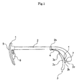
- Fig. 1 is a side view of an optical frame according to the first embodiment of the present invention
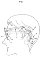
- Fig. 2 is a schematic view showing a case where the optical frame of Fig. 1 is worn.
- the optical frame comprises a front frame 1 which holds lenses 5, a pair of temples 2 each of which extends backward from both ends of the front frame 1, an ear pad member 3 which has an ear contacting portion 3a contactable to a back of an ear and an oscillating portion 3b with a shaft member 7, such as a pin or a screw, for attaching a rear portion of the temple 2 and the ear contacting portion 3a in a freely oscillating manner, and a flexible tangle preventing member 4 which couples a predetermined portion 2b positioned anterior to a part 2a of the temple 2, where the ear pad member 3 is attached, and a front end 3c of the ear contacting portion 3a.
- a front frame 1 which holds lenses 5
- a pair of temples 2 each of which extends backward from both ends of the front frame 1
- an ear pad member 3 which has an ear contacting portion 3a contactable to a back of an ear and an oscillating portion 3b with a shaft member 7, such as
- a pad 6 for a nose pad is attached to the front frame 1 and, as shown in Fig. 2 , glasses are worn by placing the pad 6 on the nose and, also, hooking the ear contacting portion 3a of the curved ear pad member 3 on a curved portion at the back of the ear (between ear and head).
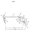
- Fig. 3 is a side view of the optical frame for describing oscillation of the ear pad member.
- the front frame 1 starts to slip down in a state where the glasses are worn (state A of Fig. 2 , and a state shown with a broken line of the ear pad member 3 of Fig. 3 )
- the rear portion of the temple 2 extending from the front frame 1 starts to slip upward, thereby moving the ear contacting portion 3a of the ear pad member 3 attached to the rear portion of the temple 2 upward.
- the ear contacting portion 3a of the ear pad member 3 starts to move upward, the ear contacting portion 3a starts to rotate in a front-rotation direction (in a left rotation direction in Fig. 3 ) with the use of the shaft member 7 passed through the oscillating portion 3b of the ear pad member 3, i.e., a part where the temple 2 is attached, (part 2a of the temple 2, where the ear pad member 3 is attached) as a rotational center (the ear contacting portion 3a of Fig. 3 starts to move to a state shown with a solid line).
- the force of the front end 3c of the ear contacting portion 3a pressing against the back of the ear becomes greater and, as a result, the relative movement between the ear contacting portion 3a and the back of the ear is hindered (the ear contacting portion 3a of Fig. 3 starts to return to a state shown with a broken line) and the slipping up of the rear portion of the temple 2 is prevented.
- the glasses can be thereby prevented from slipping down.
- the present embodiment is configured so that the oscillating portion 3b is provided at an almost intermediate portion of the ear contacting portion 3a in a longitudinal direction thereof.
- a regulating mechanism 8 for regulating the oscillating range of the oscillating portion 3b is provided at the oscillating portion 3b of the ear pad member 3, i.e., a part to which the temple 2 is attached, and at the part 2a of the temple 2, where the ear pad member 3 is attached.
- the shaft member 7 such as a pin or a screw is used to attach the temple 2 and the oscillating portion 3b of the ear pad member 3.
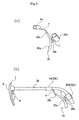
- Fig. 4 is an enlarged view in the vicinity of the attaching portion of the temple and the ear pad member in the optical frame of Fig. 1 .
- the regulating mechanism 8 regulates the oscillation by contacting a supporting strip 38 of the oscillating portion 3b of the ear pad member 3 to a contacting surface 38 provided at the part 2a of the temple 2, where the ear pad member is attached, as shown in Fig. 4 .
- the oscillating range of the ear pad member 3 is regulated by providing the regulating mechanism 8, so that when a user wears the glasses, the ear contacting portion 3a of the ear pad member 3 can easily contact an appropriate portion of the back of the ear and the user can easily wear the glasses.
- the regulating mechanism 8 can be easily configured by providing the regulating mechanism 8 about the shaft of the shaft member 7. It is to be noted that although the oscillating portion 3b attached to the ear pad member 3 is attached to the shaft member 7 in a freely oscillating manner in this embodiment, a hole may be opened in the ear pad member 3 itself (ear contacting portion 3a) to allow the ear contacting member 3 to be attached to the temple 2 by way of the shaft member 7 in a freely oscillating manner.
- the part 2a of the temple 2, where the ear pad member 3 is attached is configured so as to serve as the rear end of the temple 2.
- the optical frame can be made similar to the shape of the conventional optical frame, and even the users using the optical frame of a conventionally typical shape can wear the optical frame without feeling uncomfortable.
- FIG. 2 A mode of tangle prevention of the hair to the glasses in the optical frame of this embodiment will now be described with reference to Fig. 2 .
- the flexible tangle preventing member 4 is attached so as to couple the predetermined portion 2b anterior to the part 2a of the temple 2, where the ear pad member 3 is attached, and the front end 3c of the ear contacting portion 3a of the ear pad member 3. Even when the temple 2 is lifted upward (state B of Fig.
- the space between the temple 2 and the front end 3c of the ear contacting portion 3a is blocked by the tangle preventing member 4, so that the hair is less likely to enter the attaching portion (oscillating portion 3b) of the temple 2 and the ear contacting portion 3a from the x direction and the tangling thereto is suppressed. Further, since the tangle preventing member 4 has flexibility, the function of suppressing slipping down of the glasses will not be inhibited.
- the glasses are prevented from slipping down without increasing the load on the nose, and the tangling of the hair to the glasses are suppressed upon taking off the glasses.
- the tangle preventing member 4 is an elastic member such as an elastomer and is configured so as to switch between a posture for acting an elastic force f A to press the front end 3c of the ear contacting portion 3a to the temple 2 side (state A), and a posture for acting an elastic force f B to move the front end 3c of the ear contacting portion 3a away from the temple 2 (state B).
- the tangle preventing member 4 is made by an elastic member such as an elastomer, and assuming a predetermined position as a switch point, on the side in which the front end 3c of the ear contacting portion 3a is closer to the temple than the switch point, the elastic force f A shown in Fig. 3 is acted and the front end 3c of the ear contacting portion 3a is held at a position pressed against the temple 2 side as in the state A.
- the tangle preventing member 4 bends, causing the direction the elastic force acts to reverse, and thus the elastic force f B shown in Fig. 3 is acted and the front end 3c of the ear contacting portion 3a is held at a position apart from the temple 2 as in the state B.
- a distance L B between the lens 5 (front frame 1) and the rear end of the tangle preventing member 4 is wider than a distance L A in the state B.
- the posture of the tangle preventing member 4 is switched to the posture (state A) for acting the elastic force f A to press the front end 3c of the ear contacting portion 3a to the temple 2 side and the rear end of the ear contacting portion 3a securely contacts the back of the ear.
- the tangle preventing member 4 can switch the postures of the ear contacting portion 3a by means the elastic force thereof, the glasses can be more easily worn and, also, the slipping down of the glasses can be more effectively suppressed.
- the tangle preventing member 4 can suitably switch the direction of the elastic force by suitably selecting the combination of an elastic coefficient, thickness and length of the elastic member used for the tangle preventing member 4.
- the tangle preventing member 4 various elastic members such as an elastomer (polymer substance having elasticity, such as natural rubber and synthetic rubber), and a leaf spring formed by a shape memory alloy and the like can be adopted as long as the member has elastic force.
- the tangle preventing member 4 preferably has a cross sectional shape that is long in an axial direction of the shaft member 7 such that the direction of the elastic force is almost parallel with the freely oscillating direction of the ear pad member 3 (so as not to shift in the axial direction of the shaft member 7).
- Various shapes such as ellipse, semicircle, rectangle and the like may be applied for the relevant cross sectional shape. It may be hollow or solid and may be formed by weaving into a fiber form.
- the elastic member is used for the tangle preventing member 4, but for the material to achieve tangle prevention (when switch of elastic force is not required), any kind of material (may of course be elastic member) may be used as long as the material has flexibility, such as nylon resin.
- the tangle preventing member 4 can be configured strong and soft at low cost. Further, it may be formed as one unit (may be solid or hollow) or may be formed by weaving into a fiber form.
- the predetermined portion 2b of the temple 2, where the tangle preventing member 4 is attached may be fixed to a predetermined part of the temple 2, or may be attached so as to be slidable along the temple 2.
- FIG. 5 is a side view of an optical frame attachment according to the second embodiment of the present invention and an optical frame attached therewith.
- Fig. 5(a) shows the optical frame attachment
- Fig. 5(b) shows a case where the optical frame attachment is attached to a typical optical frame.
- an optical frame attachment 30 is an optical frame attachment 30 removably attached to the optical frame including a front frame 1 for holding the lenses and a pair of temples 20 each extending backward from both ends of the front frame 1 as shown in Fig. 5 , and the optical frame attachment 30 comprises a clip portion 30d removably attached to a rear end 20a of the temple 20, an ear contacting portion 30a contactable to a back of an ear, and an oscillating portion 30b to which the shaft member 7 such as a pin or a screw is attached for attaching the clip portion 30d and the ear contacting portion 30a in a freely oscillating manner.
- the optical frame attachment 30 of this embodiment is removably attached to the rear end 20a of the temple of a typical optical frame with the clip portion 30d.
- the clip portion 30d and the ear contacting portion 30a are attached in a freely oscillating manner using the shaft member 7 such as a pin or a screw by the oscillating portion 30b.
- the temple 20 of the optical frame and the ear contacting portion 30a of the optical frame attachment 30 are thereby attached in a freely oscillating manner.
- the clip portion 30d in the optical frame attachment 30 of this embodiment is made of a flexible member such as rubber or resin, and is formed, as shown in Fig. 5(a) , into an almost tubular body, i.e., formed into an almost tubular body in which the cross section has an almost similar shape as that of the temple 20, and the inner diameter thereof is set to be slightly smaller than the outer diameter of the temple 20 fitted thereto.
- An opening with a width narrower than the diameter of the tubular body is formed along the longitudinal direction of the tubular body in the clip portion 30d, and the temple 20 is fitted by being inserted through the opening of the tubular body.
- the clip portion 30d When attaching to most of the typical optical frame having a shape in which the temple 20 gradually thickens toward the rear side, even if a predetermined space is given at the inner diameter of the clip portion 30d, the clip portion 30d can be prevented from slipping off from the rear end of the temple 20.
- the shape, the material and the like of the clip portion 30d is not limited to those mentioned above and shown in the accompanying drawings, and may be modified within a scope not departing from the purpose of the present invention.
- a mode of slippage prevention of the optical frame ( Fig. 5(b) ) attached with the optical frame attachment 30 of this embodiment is similar to the optical frame of the first embodiment; therefore, the description thereof will not be given herein.
- the glasses can be prevented from slipping down without using a special optical frame and without increasing the load on the nose with respect to the optical frame.
- the optical frame attachment 30 to the optical frame of various designs, an effective effect of preventing the glasses from slipping down in any kind of optical frame can be achieved with only one (a pair of) optical frame attachment.
- a flexible tangle preventing member 4 is further provided, which has a first end coupled to the front end 30c of the ear contacting portion 30a and a second end removably attached to a predetermined portion 20b positioned anterior to a part 20a of the temple 20 where the clip portion 30b of the temple 20 is attached.
- the flexible tangle preventing member 4 is attached so as to couple the predetermined portion 20b anterior to the part 20a, where the clip portion 30d is attached, of the temple 20 of the optical frame and the front end 30c of the ear contacting portion 30a of the optical frame attachment 30. Even when the temple 20 is lifted upward upon taking off the glasses, since the space between the temple 20 and the front end 30c of the ear contacting portion 30a is blocked by the tangle preventing member 4, the hair is less likely to enter the attaching portion (oscillating portion 30b) of the temple 20 and the ear contacting portion 30a, and tangling thereto is suppressed.
- the tangle preventing member 4 has flexibility and does not inhibit the oscillation of the ear contacting portion 30a of the optical frame attachment 20, and thus does not inhibit the function of suppressing the slipping down of the glasses.
- the glasses can be prevented from slipping down without increasing the load on the nose, and the tangling of the hair to the glasses can be suppressed upon taking off the glasses.
- the tangle preventing member 4 is also configured so as to be made of elastomer, nylon resin or the like. In this case, when made of elastomer, nylon resin or the like, the tangle preventing member 4 is configured strong and soft at low cost.
- the tangle preventing member 4 may be made of any material as long as the material has flexibility, and may be formed as one unit (may be solid or hollow) or may be formed by weaving into a fiber form.
- a clip portion 4a made of a flexible member such as elastomer or resin similar to the clip portion 30d is used.
- the predetermined portion 20b of the temple 20, where the clip portion 4a of the tangle preventing member 4 is attached may be fixed to a predetermined part of the temple 20 without sliding of the clip portion 4a, or may be slidably attached along the temple 20.
- the tangle preventing member 4 is an elastic material such as an elastomer, and thus may be configured so as to switch between a posture for acting the elastic force f A to press the front end 3c of the ear contacting portion 3a against the temple 2 side (state A) and a posture for acting the elastic force f B to move the front end 3c of the ear contacting portion 3a away from the temple 2 (state B).
- the clip portion 4a made of a flexible member is used as a mode of attachment to the temple 20 of the tangle preventing member 4, but attachment may also be performed by forming a hole through which the temple 20 passes at an end, to which the temple 20 is attached, of the tangle preventing member 4, and passing the temple 20 through the hole.
- the diameter of the hole is set to be slightly smaller than the predetermined portion 20b of the temple 20. If the outer diameter of the rear end of the temple 20 is large and can not pass through the hole, the front frame 1 and the temple 20 are disassembled once and after passing the temple 20 through the hole of the tangle preventing member 4, the front frame 1 and the temple 20 are again assembled.
- the glasses can be prevented from slipping down without increasing the load on the nose, and the tangling of the hair to the glasses can be suppressed upon taking off the glasses.
Landscapes
- Physics & Mathematics (AREA)
- Health & Medical Sciences (AREA)
- General Physics & Mathematics (AREA)
- Ophthalmology & Optometry (AREA)
- Optics & Photonics (AREA)
- Eyeglasses (AREA)
Claims (7)
- Dispositif supplémentaire de monture de lunettes pouvant être attaché à une monture de lunettes et en démontable, ladite monture de lunettes comprenant une monture avant (1) pour supporter des lentes (5), et une paire de branches (20) chacune desdites branches s'étendant à partir des deux extrémités de ladite monture avant (1) vers l'arrière, ledit dispositif supplémentaire de monture de lunettes comprenant:une partie à serrage (30d) pouvant être attachée à une partie arrière de ladite branche et en démontable;une partie de contact (30a) à mettre en contact avec l'oreille, pouvant être attachée à ladite partie à serrage (30d) d'une manière oscillante libre à l'aide d'un élément d'arbre (7), et pouvant être mise en contact avec la face arrière d'une oreille; etun membre souple anti-enchevêtrement (4) ayant une première extrémité reliée à une extrémité avant (30c) de ladite partie de contact (30a) à mettre en contact avec l'oreille et une deuxième extrémité pouvant être attachée à une partie prédestinée (20b) et en démontable, ladite partie prédestinée (20b) étant antérieure à une partie de ladite branche (20) où ladite partie à serrage (30d) est attachée,ledit membre anti-enchevêtrement (4) étant un membre élastique et étant arrangé à changer de position entre une position d'exercer une force élastique (fA) pour presser ladite extrémité avant (30c) de ladite partie de contact (30a) à mettre en contact avec l'oreille vers le côté de ladite branche et une position d'exercer une force élastique (fB) pour écarter ladite extrémité avant (30c) de ladite partie de contact (30a) à mettre en contact avec l'oreille de ladite branche (20),caractérisé en ce que
ledit membre anti-enchevêtrement (4) est arrangé à permettre d'obtenir une position prédestinée comme un point de renversement, lorsque ladite extrémité avant (30c) de ladite partie de contact (30a) à mettre en contact avec l'oreille est dans une position plus près de ladite branche (20) que ledit point de renversement, une première force élastique (fA) est exercée de sorte que ladite extrémité avant (30c) de ladite partie de contact (30a) à mettre en contact avec l'oreille est retenue dans une position pressée vers ledit côté de ladite branche, et lorsque ladite extrémité avant (30c) de ladite partie de contact (30a) à mettre en contact avec l'oreille est déplacée dans une position écartée de ladite branche (20) derrière ledit point de renversement, ledit membre anti-enchevêtrement (4) est courbé ayant pour effet que la direction dans laquelle ladite force est exercée est renversée, et ainsi une deuxième force élastique (fB) agit sur ladite extrémité avant (30c) de ladite partie de contact (30a) à mettre en contact avec l'oreille pour la retenir dans une position écartée de ladite branche (20). - Dispositif supplémentaire de monture de lunettes selon la revendication 1, ladite partie de contact (30a) à mettre en contact avec l'oreille pivotant de va-et-vient en utilisant ledit élément d'arbre (7) comme un centre de rotation.
- Dispositif supplémentaire de monture de lunettes selon la revendication 1 ou 2, ladite partie à serrage (30d) étant attachée à une partie de ladite partie de contact (30a) à mettre en contact avec l'oreille presque intermédiaire en sa longueur.
- Monture de lunettes équipée dudit dispositif supplémentaire de monture de lunettes selon l'une quelconque des revendications 1 à 3.
- Monture de lunettes, comprenant:une monture avant (1) pour supporter des lentes (5);une paire de branches (2) chacune desdites branches s'étendant à partir des deux extrémités de ladite monture avant (1);un membre d'appui d'oreille (3) ayant une partie de contact (3a) à mettre en contact avec l'oreille, étant attachée à ladite partie arrière de ladite branche (2) d'une manière oscillante libre à l'aide d'un élément d'arbre (7), et pouvant être mise en contact avec une face arrière d'une oreille; etun membre souple anti-enchevêtrement (4) pour coupler une partie prédestinée (2b) antérieure à une partie de ladite branche (2) où ledit membre d'appui d'oreille (3) est attaché, à une extrémité avant (3c) de ladite partie de contact (3a) à mettre en contact avec l'oreille,ledit membre anti-enchevêtrement (4) étant un membre élastique et étant arrangé à changer de position entre une position d'exercer une force élastique (fA) pour presser ladite extrémité avant (3c) de ladite partie de contact (3a) à mettre en contact avec l'oreille vers le côté de ladite branche et une position d'exercer une force élastique (fB) pour écarter ladite extrémité avant (3c) de ladite partie de contact (3a) à mettre en contact avec l'oreille de ladite branche (2),caractérisé en ce que
ledit membre anti-enchevêtrement (4) est arrangé à permettre d'obtenir une position prédestinée comme un point de renversement, lorsque ladite extrémité avant (3c) de ladite partie de contact (3a) à mettre en contact avec l'oreille est dans une position plus près de ladite branche (2) que ledit point de renversement, une première force élastique (fA) est exercée de sorte que ladite extrémité avant (3c) de ladite partie de contact (3a) à mettre en contact avec l'oreille est retenue dans une position pressée vers ledit côté de ladite branche, et lorsque ladite extrémité avant (3c) de ladite partie de contact (3a) à mettre en contact avec l'oreille est déplacée dans une position écartée de ladite branche (2) derrière ledit point de renversement, ledit membre anti-enchevêtrement (4) est courbé ayant pour effet que la direction dans laquelle ladite force est exercée est renversée, et ainsi une deuxième force élastique (fB) agit sur ladite extrémité avant (3c) de ladite partie de contact (3a) à mettre en contact avec l'oreille pour la retenir dans une position écartée de ladite branche (2). - Monture de lunettes selon la revendication 5, ladite partie de contact (3a) à mettre en contact avec l'oreille pivotant de va-et-vient ayant ledit élément d'arbre (7) comme un centre de rotation.
- Monture de lunettes selon la revendication 5 ou 6, ladite partie arrière de ladite branche (2) étant attachée à une partie de ladite partie de contact (3a) à mettre en contact avec l'oreille presque intermédiaire.
Applications Claiming Priority (5)
| Application Number | Priority Date | Filing Date | Title |
|---|---|---|---|
| JP2003174571 | 2003-06-19 | ||
| JP2003174571 | 2003-06-19 | ||
| JP2003356187 | 2003-10-16 | ||
| JP2003356187A JP3526571B1 (ja) | 2003-06-19 | 2003-10-16 | 眼鏡取り付け具および眼鏡フレーム |
| PCT/JP2004/004033 WO2004113995A1 (fr) | 2003-06-19 | 2004-03-24 | Dispositif d'installation de lunettes et monture de lunettes |
Publications (3)
| Publication Number | Publication Date |
|---|---|
| EP1569028A1 EP1569028A1 (fr) | 2005-08-31 |
| EP1569028A4 EP1569028A4 (fr) | 2006-02-08 |
| EP1569028B1 true EP1569028B1 (fr) | 2010-03-24 |
Family
ID=32473775
Family Applications (1)
| Application Number | Title | Priority Date | Filing Date |
|---|---|---|---|
| EP04723020A Expired - Lifetime EP1569028B1 (fr) | 2003-06-19 | 2004-03-24 | Dispositif d'installation de lunettes et monture de lunettes |
Country Status (6)
| Country | Link |
|---|---|
| US (1) | US7018038B2 (fr) |
| EP (1) | EP1569028B1 (fr) |
| JP (1) | JP3526571B1 (fr) |
| DE (1) | DE602004026156D1 (fr) |
| TW (1) | TWI266099B (fr) |
| WO (1) | WO2004113995A1 (fr) |
Families Citing this family (11)
| Publication number | Priority date | Publication date | Assignee | Title |
|---|---|---|---|---|
| JP4486954B2 (ja) * | 2006-12-27 | 2010-06-23 | 株式会社ビジョンメガネ | 眼鏡フレーム |
| JP2010072511A (ja) * | 2008-09-22 | 2010-04-02 | Planet Vision60 Co Ltd | 眼鏡取り付け具及び眼鏡フレームセット |
| US8894200B2 (en) | 2010-06-30 | 2014-11-25 | Addo Industries, Llc | Innovative and aesthetic alternative to traditional spectacle correction |
| CN103439799A (zh) * | 2013-09-02 | 2013-12-11 | 太仓市旭冉机械有限公司 | 一种眼镜架 |
| US20160077357A1 (en) * | 2014-09-17 | 2016-03-17 | Alice Marie Miller | Height Adjustment System for Eyeglasses |
| USD751140S1 (en) * | 2014-12-04 | 2016-03-08 | Pinna Ly | Eyeglasses holder |
| US9733487B2 (en) | 2014-12-04 | 2017-08-15 | Pinna Ly | Retaining device |
| US10261338B2 (en) * | 2015-01-15 | 2019-04-16 | Addo Industries, Llc | Eyewear comprising suspension system for nose and ears |
| US10761349B2 (en) * | 2017-02-02 | 2020-09-01 | Arthur N. Foss | Dual-frame eyeglasses |
| USD898816S1 (en) * | 2019-11-27 | 2020-10-13 | Shenzhen Top Optic Co., Ltd | Eyeglasses temple tip hook |
| CN115230966B (zh) * | 2022-09-01 | 2025-11-18 | 杭州启飞智能科技有限公司 | 播撒器 |
Family Cites Families (12)
| Publication number | Priority date | Publication date | Assignee | Title |
|---|---|---|---|---|
| US4389102A (en) * | 1980-11-17 | 1983-06-21 | Piampiano Carl P | Eyeglass temple bar retaining means |
| DE8423472U1 (de) * | 1984-08-07 | 1987-10-29 | Anger, Wilhelm, St. Moritz | Bügelendstück für einen Bügel einer Brillenfassung |
| DE3446184C2 (de) * | 1984-12-18 | 1987-01-08 | Anger, Wilhelm, St. Moritz | Bügelendstück für einen Bügel einer Brillenfassung |
| DE8520246U1 (de) * | 1985-07-12 | 1988-03-24 | Anger, Wilhelm, St. Moritz | Bügelendstück für einen Bügel einer Brillenfassung |
| DE3525006A1 (de) * | 1985-07-12 | 1987-01-22 | Wilhelm Anger | Buegelendstueck fuer einen buegel einer brillenfassung |
| JPH0614188Y2 (ja) | 1988-05-02 | 1994-04-13 | 株式会社ハセガワ・ビコー | メガネの固定具 |
| US4863257A (en) * | 1988-09-26 | 1989-09-05 | Morgan Richard H | Eyeglass loop connection |
| JPH02119618U (fr) | 1989-03-15 | 1990-09-26 | ||
| FR2706637B1 (fr) | 1993-06-11 | 1995-10-27 | Pentax Vision Co Ltd | Monture de lunettes. |
| JPH07209616A (ja) * | 1994-01-19 | 1995-08-11 | Masunaga Megane Kk | 眼鏡におけるテンプルのクッション・モダン調節機構、およびそれに用いるアジャスト式クッション・モダン |
| EP0807277B1 (fr) * | 1995-02-01 | 2000-07-19 | Luxottica Leasing S.p.A. | Tempes pour lunettes |
| IT1292669B1 (it) * | 1997-02-20 | 1999-02-11 | Togna Service S A S Di Poloni | Asta per occhiali. |
-
2003
- 2003-10-16 JP JP2003356187A patent/JP3526571B1/ja not_active Expired - Fee Related
-
2004
- 2004-03-24 EP EP04723020A patent/EP1569028B1/fr not_active Expired - Lifetime
- 2004-03-24 US US10/513,929 patent/US7018038B2/en not_active Expired - Fee Related
- 2004-03-24 WO PCT/JP2004/004033 patent/WO2004113995A1/fr not_active Ceased
- 2004-03-24 DE DE602004026156T patent/DE602004026156D1/de not_active Expired - Lifetime
- 2004-06-01 TW TW093115692A patent/TWI266099B/zh active
Also Published As
| Publication number | Publication date |
|---|---|
| HK1077366A1 (en) | 2006-02-10 |
| DE602004026156D1 (de) | 2010-05-06 |
| US20050168680A1 (en) | 2005-08-04 |
| EP1569028A1 (fr) | 2005-08-31 |
| TWI266099B (en) | 2006-11-11 |
| JP3526571B1 (ja) | 2004-05-17 |
| WO2004113995A1 (fr) | 2004-12-29 |
| TW200506432A (en) | 2005-02-16 |
| US7018038B2 (en) | 2006-03-28 |
| JP2005031616A (ja) | 2005-02-03 |
| EP1569028A4 (fr) | 2006-02-08 |
Similar Documents
| Publication | Publication Date | Title |
|---|---|---|
| US3397026A (en) | Adjustable eyeglass retaining strap | |
| US6139143A (en) | Temple for eyewear having an integrally formed serpentine hinge | |
| AU719220B2 (en) | Spring temple for eyewear | |
| US7018038B2 (en) | Spectacle installation device and spectacle frame | |
| EP0666491A1 (fr) | Plaquette nasale, en particulier pour lunettes | |
| AU4769196A (en) | Temple for eyewear | |
| US5440356A (en) | Spectacle frame including self-aligning temple end piece | |
| US5790229A (en) | Temple for spectacles | |
| JP3101056U (ja) | 眼鏡取り付け具および眼鏡フレーム | |
| US6000797A (en) | Spectacles | |
| HK31997A (en) | Earstem for eyeglasses | |
| US4047809A (en) | Spectacles having adjustable temples | |
| EP0698801A1 (fr) | Mecanisme de reglage d'element terminal de support pour branches de lunettes et element terminal de support reglable utilise | |
| JP2003121800A (ja) | メガネフレームのツル | |
| HK1077366B (en) | Spectacle installation device and spectacle frame | |
| JP2018194643A (ja) | 眼鏡の支持具 | |
| EP0944854A1 (fr) | Branche de lunettes sans charniere | |
| US7441891B2 (en) | Eyeglass retainer | |
| CN100357791C (zh) | 眼镜配件以及眼镜框架 | |
| JP3111284U (ja) | 眼鏡フレーム用テンプル | |
| JP3732209B1 (ja) | 眼鏡フレーム用テンプル | |
| CN109716210B (zh) | 具有延伸部的眼镜 | |
| JP3490552B2 (ja) | 眼鏡フレーム | |
| JP3108981U (ja) | 眼鏡フレーム用テンプル | |
| JP2008292748A (ja) | 眼鏡ツルのモダン部長さ調整構造 |
Legal Events
| Date | Code | Title | Description |
|---|---|---|---|
| PUAI | Public reference made under article 153(3) epc to a published international application that has entered the european phase |
Free format text: ORIGINAL CODE: 0009012 |
|
| 17P | Request for examination filed |
Effective date: 20050629 |
|
| AK | Designated contracting states |
Kind code of ref document: A1 Designated state(s): AT BE BG CH CY CZ DE DK EE ES FI FR GB GR HU IE IT LI LU MC NL PL PT RO SE SI SK TR |
|
| AX | Request for extension of the european patent |
Extension state: AL LT LV MK |
|
| A4 | Supplementary search report drawn up and despatched |
Effective date: 20051222 |
|
| RIC1 | Information provided on ipc code assigned before grant |
Ipc: G02C 5/14 20060101AFI20051216BHEP Ipc: G02C 11/00 20060101ALI20051216BHEP Ipc: G02C 5/16 20060101ALI20051216BHEP |
|
| REG | Reference to a national code |
Ref country code: HK Ref legal event code: DE Ref document number: 1077366 Country of ref document: HK |
|
| DAX | Request for extension of the european patent (deleted) | ||
| RBV | Designated contracting states (corrected) |
Designated state(s): DE FR GB IT |
|
| GRAP | Despatch of communication of intention to grant a patent |
Free format text: ORIGINAL CODE: EPIDOSNIGR1 |
|
| RIN1 | Information on inventor provided before grant (corrected) |
Inventor name: UEKAJI, M.,VISION OPTIC CO., LTD. Inventor name: YOSHIDA, T.,VISION OPTIC CO., LTD. |
|
| GRAS | Grant fee paid |
Free format text: ORIGINAL CODE: EPIDOSNIGR3 |
|
| GRAA | (expected) grant |
Free format text: ORIGINAL CODE: 0009210 |
|
| AK | Designated contracting states |
Kind code of ref document: B1 Designated state(s): DE FR GB IT |
|
| REG | Reference to a national code |
Ref country code: GB Ref legal event code: FG4D |
|
| REF | Corresponds to: |
Ref document number: 602004026156 Country of ref document: DE Date of ref document: 20100506 Kind code of ref document: P |
|
| REG | Reference to a national code |
Ref country code: HK Ref legal event code: GR Ref document number: 1077366 Country of ref document: HK |
|
| PLBE | No opposition filed within time limit |
Free format text: ORIGINAL CODE: 0009261 |
|
| STAA | Information on the status of an ep patent application or granted ep patent |
Free format text: STATUS: NO OPPOSITION FILED WITHIN TIME LIMIT |
|
| 26N | No opposition filed |
Effective date: 20101228 |
|
| PGFP | Annual fee paid to national office [announced via postgrant information from national office to epo] |
Ref country code: DE Payment date: 20140331 Year of fee payment: 11 |
|
| PGFP | Annual fee paid to national office [announced via postgrant information from national office to epo] |
Ref country code: FR Payment date: 20140319 Year of fee payment: 11 Ref country code: IT Payment date: 20140327 Year of fee payment: 11 |
|
| PGFP | Annual fee paid to national office [announced via postgrant information from national office to epo] |
Ref country code: GB Payment date: 20140319 Year of fee payment: 11 |
|
| REG | Reference to a national code |
Ref country code: DE Ref legal event code: R119 Ref document number: 602004026156 Country of ref document: DE |
|
| GBPC | Gb: european patent ceased through non-payment of renewal fee |
Effective date: 20150324 |
|
| PG25 | Lapsed in a contracting state [announced via postgrant information from national office to epo] |
Ref country code: IT Free format text: LAPSE BECAUSE OF NON-PAYMENT OF DUE FEES Effective date: 20150324 |
|
| REG | Reference to a national code |
Ref country code: FR Ref legal event code: ST Effective date: 20151130 |
|
| PG25 | Lapsed in a contracting state [announced via postgrant information from national office to epo] |
Ref country code: DE Free format text: LAPSE BECAUSE OF NON-PAYMENT OF DUE FEES Effective date: 20151001 Ref country code: GB Free format text: LAPSE BECAUSE OF NON-PAYMENT OF DUE FEES Effective date: 20150324 |
|
| PG25 | Lapsed in a contracting state [announced via postgrant information from national office to epo] |
Ref country code: FR Free format text: LAPSE BECAUSE OF NON-PAYMENT OF DUE FEES Effective date: 20150331 |