EP1568837B1 - Fenster - Google Patents
Fenster Download PDFInfo
- Publication number
- EP1568837B1 EP1568837B1 EP20050100481 EP05100481A EP1568837B1 EP 1568837 B1 EP1568837 B1 EP 1568837B1 EP 20050100481 EP20050100481 EP 20050100481 EP 05100481 A EP05100481 A EP 05100481A EP 1568837 B1 EP1568837 B1 EP 1568837B1
- Authority
- EP
- European Patent Office
- Prior art keywords
- window
- hinge pin
- hinge
- bearing
- frame
- Prior art date
- Legal status (The legal status is an assumption and is not a legal conclusion. Google has not performed a legal analysis and makes no representation as to the accuracy of the status listed.)
- Expired - Lifetime
Links
- 239000002184 metal Substances 0.000 claims description 4
- 238000000465 moulding Methods 0.000 description 5
- 229910000639 Spring steel Inorganic materials 0.000 description 2
- 230000015572 biosynthetic process Effects 0.000 description 2
- 230000002349 favourable effect Effects 0.000 description 2
- 239000011521 glass Substances 0.000 description 2
- 239000000463 material Substances 0.000 description 2
- 239000004033 plastic Substances 0.000 description 2
- 229920003023 plastic Polymers 0.000 description 2
- 238000005452 bending Methods 0.000 description 1
- 238000004140 cleaning Methods 0.000 description 1
- 238000010276 construction Methods 0.000 description 1
- 238000007598 dipping method Methods 0.000 description 1
- 238000006073 displacement reaction Methods 0.000 description 1
- 239000000945 filler Substances 0.000 description 1
- 238000009434 installation Methods 0.000 description 1
- 238000000034 method Methods 0.000 description 1
- 230000001151 other effect Effects 0.000 description 1
- 239000002023 wood Substances 0.000 description 1
Images


Classifications
-
- E—FIXED CONSTRUCTIONS
- E05—LOCKS; KEYS; WINDOW OR DOOR FITTINGS; SAFES
- E05D—HINGES OR SUSPENSION DEVICES FOR DOORS, WINDOWS OR WINGS
- E05D7/00—Hinges or pivots of special construction
- E05D7/10—Hinges or pivots of special construction to allow easy separation or connection of the parts at the hinge axis
- E05D7/1061—Hinges or pivots of special construction to allow easy separation or connection of the parts at the hinge axis in a radial direction
-
- E—FIXED CONSTRUCTIONS
- E05—LOCKS; KEYS; WINDOW OR DOOR FITTINGS; SAFES
- E05D—HINGES OR SUSPENSION DEVICES FOR DOORS, WINDOWS OR WINGS
- E05D3/00—Hinges with pins
- E05D3/02—Hinges with pins with one pin
- E05D3/022—Hinges with pins with one pin allowing an additional lateral movement, e.g. for sealing
-
- E—FIXED CONSTRUCTIONS
- E06—DOORS, WINDOWS, SHUTTERS, OR ROLLER BLINDS IN GENERAL; LADDERS
- E06B—FIXED OR MOVABLE CLOSURES FOR OPENINGS IN BUILDINGS, VEHICLES, FENCES OR LIKE ENCLOSURES IN GENERAL, e.g. DOORS, WINDOWS, BLINDS, GATES
- E06B3/00—Window sashes, door leaves, or like elements for closing wall or like openings; Layout of fixed or moving closures, e.g. windows in wall or like openings; Features of rigidly-mounted outer frames relating to the mounting of wing frames
- E06B3/32—Arrangements of wings characterised by the manner of movement; Arrangements of movable wings in openings; Features of wings or frames relating solely to the manner of movement of the wing
- E06B3/34—Arrangements of wings characterised by the manner of movement; Arrangements of movable wings in openings; Features of wings or frames relating solely to the manner of movement of the wing with only one kind of movement
- E06B3/38—Arrangements of wings characterised by the manner of movement; Arrangements of movable wings in openings; Features of wings or frames relating solely to the manner of movement of the wing with only one kind of movement with a horizontal axis of rotation at the top or bottom of the opening
-
- E—FIXED CONSTRUCTIONS
- E05—LOCKS; KEYS; WINDOW OR DOOR FITTINGS; SAFES
- E05D—HINGES OR SUSPENSION DEVICES FOR DOORS, WINDOWS OR WINGS
- E05D15/00—Suspension arrangements for wings
- E05D15/48—Suspension arrangements for wings allowing alternative movements
-
- E—FIXED CONSTRUCTIONS
- E05—LOCKS; KEYS; WINDOW OR DOOR FITTINGS; SAFES
- E05D—HINGES OR SUSPENSION DEVICES FOR DOORS, WINDOWS OR WINGS
- E05D5/00—Construction of single parts, e.g. the parts for attachment
- E05D5/10—Pins, sockets or sleeves; Removable pins
- E05D5/12—Securing pins in sockets, movably or not
-
- E—FIXED CONSTRUCTIONS
- E05—LOCKS; KEYS; WINDOW OR DOOR FITTINGS; SAFES
- E05D—HINGES OR SUSPENSION DEVICES FOR DOORS, WINDOWS OR WINGS
- E05D5/00—Construction of single parts, e.g. the parts for attachment
- E05D5/10—Pins, sockets or sleeves; Removable pins
- E05D5/14—Construction of sockets or sleeves
- E05D5/16—Construction of sockets or sleeves to be secured without special attachment parts on the socket or sleeve
-
- E—FIXED CONSTRUCTIONS
- E05—LOCKS; KEYS; WINDOW OR DOOR FITTINGS; SAFES
- E05Y—INDEXING SCHEME ASSOCIATED WITH SUBCLASSES E05D AND E05F, RELATING TO CONSTRUCTION ELEMENTS, ELECTRIC CONTROL, POWER SUPPLY, POWER SIGNAL OR TRANSMISSION, USER INTERFACES, MOUNTING OR COUPLING, DETAILS, ACCESSORIES, AUXILIARY OPERATIONS NOT OTHERWISE PROVIDED FOR, APPLICATION THEREOF
- E05Y2201/00—Constructional elements; Accessories therefor
- E05Y2201/60—Suspension or transmission members; Accessories therefor
- E05Y2201/622—Suspension or transmission members elements
- E05Y2201/638—Cams; Ramps
-
- E—FIXED CONSTRUCTIONS
- E05—LOCKS; KEYS; WINDOW OR DOOR FITTINGS; SAFES
- E05Y—INDEXING SCHEME ASSOCIATED WITH SUBCLASSES E05D AND E05F, RELATING TO CONSTRUCTION ELEMENTS, ELECTRIC CONTROL, POWER SUPPLY, POWER SIGNAL OR TRANSMISSION, USER INTERFACES, MOUNTING OR COUPLING, DETAILS, ACCESSORIES, AUXILIARY OPERATIONS NOT OTHERWISE PROVIDED FOR, APPLICATION THEREOF
- E05Y2900/00—Application of doors, windows, wings or fittings thereof
- E05Y2900/10—Application of doors, windows, wings or fittings thereof for buildings or parts thereof
- E05Y2900/13—Type of wing
- E05Y2900/148—Windows
Definitions
- the invention relates to a window according to the preamble of claim 1.
- Such a window is known from the brochure "BKV - Trbandsysteme 3D", as of 12/2002, page 25 band, which can be used in tilt or rotary wings with triangular shape.
- BKV - Trbandsysteme 3D As of 12/2002, page 25 band, which can be used in tilt or rotary wings with triangular shape.
- the displacement of the pivot axis behind the space inside the visible surface of the frame causes an approximation of the pivot axis to the building exterior sections of the hinged wing. This reduces the pivoting radius and the corner portions of the wing that tip into the frame can be swung out without colliding with the frame.
- With swivel axes, which are located in front of the room inside the visible surface of the frame it comes to the pivoting opening of the wing otherwise collisions of wings and frame, which make it impossible to open the wing
- a disadvantage of the known hinge fitting is that the entire hinge fitting must be released from the frame for disassembly of the wing, since the hinge pin is inaccessible in the frame-side recess.
- the hinge fitting is attached to the frame with fixing screws which, after repeated loosening and tightening, no longer find any hold in the profile material of the frame. This applies equally to profiles made of wood and plastics but also to other materials.
- the disassembly is expensive, since the wing at an already reduced number of fasteners is no longer sufficient support on the frame and so the remaining screws are exposed to greater stress, so that damage to the wing and / or the frame in particular in the area of attachment points Consequence are.
- the invention is therefore based on the object to provide a window having an easy-to-install wing, the storage consists of a small number of easy-to-use components.
- a simple embodiment of the bearing block is achieved with the same time but also a simple and safe installation is guaranteed.
- the attachments to the frame is permanent, so that the attachment points are not exposed to any other effects except the intended loads.
- the closure element is secured against undesired removal, because the closure element can be fixed via a securing member, which consists of a slidable in the direction of the pivot axis bolt. A secure position receives the securing member in that the securing member of a thin-walled sheet -.
- each bearing eye is associated with a closure element.
- closure element together with the bearing eye at least partially forms a cylindrical cross-section extending along the pivot axis. Even if the formation of a cylindrical section for receiving the hinge pin is not essential, but this results in a favorable load on the hinge pin.
- a further embodiment provides that the slot is substantially L-shaped and the closed end lies in a vertically downwardly pointing leg of the slot. Due to the weight of the wing of the hinge pin is always displaced in the downwardly facing legs, so that the storage of the hinge pin is simplified in the vertical and horizontal direction in the slot and at the same time the wing is already secured against inadvertent removal from the pivot bearing.
- closure element prevents vertical movement of the hinge pin, so that the hinge pin is fixed in the downwardly facing leg of the L-shaped slot.
- the hinge pin is integrally formed from a cantilever, which is made of a sheet metal section and connects the pivot axis with a reaching before the rebate surface of the wing folding angle.
- the portions of the cantilever, which are effective as a pivot bearing, for example, by means of moldings can be given a cylindrical shape.
- the moldings can be attached to the corresponding sections of the cantilever, for example by means of detents.
- the cantilever includes the hinge pin, so that the molding of a joint sleeve to the cantilever is not necessary.
- triangular window 1 is the frame with 2 and the wing labeled 3.
- the wing 3 should be pivotable about a lower horizontal axis 4.
- 5 hinge fittings 6 and 7 are provided on the lower horizontal frame spar.
- the frame spar 5 is associated with a parallel extending wing spar 8, which are connected via the identical hinge fittings 6, 7.
- Such windows 1 are used for example in the roof area and adjoin the actual roof construction. Often they form the upper end of a component consisting of several windows or even balcony doors. In particular, the direct connection to the roof area complicates the cleaning of the glass surfaces of the window 1. Therefore, the wing 3 is preferably pivotally stored so far that the filling made of glass 9 can be easily cleaned from the inside.
- the wing 3 and the frame 2 should be formed from at least three profile bars or sections, which run anti-parallel to each other, so that the connection points of two profile sections of the wing 3 and the frame 2 is executed acute-angled.
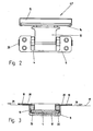
- the structure of the joint fitting 6 or 7 goes out of the FIGS. 2 to 5 out.
- the hinge fitting 6 has to be attached to the frame 2 bearing block 10, which extends with a hinge pin 12 and a cantilever 13 to a Falzwinkel 14 which is attached to the wing 3.
- a filler 15 is provided at the folding angle 14, which serves to engage in a fitting groove of the wing 3.
- the bearing block 10 has a substantially cuboidal housing 16, which is received in the mounted state in a recess of the frame 2.
- the edges of the not shown recess in the in Fig. 3 and 5 indicated visible surface 17 of the frame 2 are covered by an overhanging flange 18 and 19 in the transverse and longitudinal direction of the bearing block 10.
- the bearing pin 12 and thus also the pivot axis 4 of the wing 3 is thereby below the visible surface 17 of the frame 2, as in the Fig. 3 and 5 recognizable.
- the bearing pin 12 is associated with two bearing lugs 20 which are mounted in the lateral walls 21 of the housing 16.
- the Fig. 5 is the bearing eye 20 in a direction perpendicular to the frame plane - that is also perpendicular to the visible surface 17 - extending direction 22 formed as edge-open slot 23 or opening.
- a closure member 25 can be locked so that the hinge pin 12 is only pivotally fixed to the closed end 26 of the slot 23.
- the closure element 25 engages with a portion 27 on the hinge pin 12, so that it can not be displaced in the direction of the opening or mouth of the slot 23.
- the section 27 does not necessarily have to be arranged in a plane which coincides with the bearing eye 20. It can also be provided that the section 27 lies between the bearing eyes 20, that is to say on the surfaces facing each other. In order to achieve a secure alignment of the wing 3 during assembly in the direction of the pivot axis 4, however, it is advantageous that the hinge pin 12, as in the Fig. 3 shown supported with a collar or the like on the bearing eye 20 in the axial direction.
- the closure element 25 together with the bearing eye 20 at least partially forms a cylindrical cross section running along the pivot axis 4. This is achieved in that the closure element receives a groove at the section 27, which is matched to the cross section of the hinge pin 12.
- the formation of the cylindrical portion is not mandatory for receiving the hinge pin 12, but this results in a favorable load on the hinge pin 12 and the otherwise linear load leads to greater friction and thus wear on the closure element 25th
- the securing member 28 consists of a thin-walled sheet - for example of spring steel - which is guided below the flange 19, for example in an undercut groove. Like from the Fig. 3 it can be seen that the free end 30 of the securing member 28 is bent away from the visible surface 17, so that an operation is facilitated. In the captive position Fig. 3 it is only slightly laterally beyond the flange 19, so that it is arranged almost completely hidden. On the other hand, it is very far in the mounting position of the wing pulled out of the flange 19, so that it points conspicuously to the still-to-be-done locking.
- two bearing lugs 20 are provided, which are mounted in the side walls 21 of the housing 16, may also be provided deviating from that only a wide-sized bearing eye 20 is located centrally in the housing 16.
- the arrangement of two bearing lugs 20 makes possible a central and elongate joint sleeve or a central portion of the cantilever arm, which is received between the bearing lugs 20.
- the bearing lugs 20 are easily accessible by this arrangement.
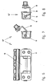
- the hinge fitting 6 is visible in different open positions. It can be seen that the cantilever arm 13 is designed so that in the closed position of the wing 3 (FIG. 4 and 5 ) as close as possible to the visible surface 17, in the maximum open position ( Fig. 8 ) but is supported on the housing 16 with the section 31 and allows a 90 ° opening of the wing 3.
- FIG. 9 another embodiment is shown in which the slot 27 is substantially L-shaped and the closed end 26 is located in a vertically downwardly facing leg 32 of the slot 27. Due to the weight of the wing 3, which acts in the direction 33, the hinge pin 12 is always displaced in the downwardly facing leg 32, so that the storage of the hinge pin 12 in the vertical and horizontal direction in the slot 27 already by the substantially cylindrical shape of the Long hole is formed in this section.
- the wing 3 is like that already basically secured against unintentional removal from the pivot bearing.
- closure element prevents a vertical movement of the hinge pin 12, so that the hinge pin 12 is fixed in the downwardly pointing leg 32 of the L-shaped elongated hole 27.
- the hinge pin 12 is formed integrally from the cantilever 13.
- the cantilever 13 is made of a sheet metal section, for example, by a punching-bending process and has two of the longitudinal edges projecting webs on. These webs can be provided with moldings, for example made of plastic, which on the one hand receive the webs and on the other hand have a cylindrical shape.
- the cantilever arm 13 includes the hinge pin 12, so that the molding of a joint sleeve and mounting and possibly setting a separate hinge pin is not necessary herein.
Landscapes
- Engineering & Computer Science (AREA)
- Mechanical Engineering (AREA)
- Civil Engineering (AREA)
- Structural Engineering (AREA)
- Hinges (AREA)
Description
- Gegenstand der Erfindung ist ein Fenster nach dem Oberbegriff des Anspruchs 1.
- Ein derartiges Fenster ist aus den Prospekt "BKV - Türbandsysteme 3D", Stand 12/2002, Seite 25 Band bekannt, welches bei Kipp- oder Drehflügeln mit dreieckiger Form eingesetzt werden kann. Hierzu ist es notwendig eine Ausnehmung am Rahmen vorzusehen, in die der Gelenkbeschlag zur Anordnung der Schwenkachse in dieser Ebene eingreifen kann. Die Verlagerung der Schwenkachse hinter die rauminnenseitige Sichtfläche des Rahmens bewirkt eine Annäherung der Schwenkachse an die gebäudeaußenseitig gelegenen Abschnitte des schwenkbaren Flügels. Dadurch reduziert sich der Schwenkradius und die spitz in den Rahmen eintauchenden Eckbereiche des Flügels können ohne mit dem Rahmen zu kollidieren ausgeschwenkt werden. Bei Schwenkachsen, die vor der rauminnenseitigen Sichtfläche des Rahmens liegen kommt es beim Schwenköffnen des Flügels ansonsten zu Kollisionen von Flügel und Rahmen, welche ein Öffnen des Flügels unmöglich machen.
- Nachteilig bei dem bekannten Gelenkbeschlag ist es, das zur Demontage des Flügels der gesamte Gelenkbeschlag vom Rahmen gelöst werden muss, da der Gelenkbolzen unzugänglich in der rahmenseitigen Ausnehmung liegt. Der Gelenkbeschlag ist mit Befestigungsschrauben an dem Rahmen angebracht, die nach mehrmaligem lösen und festziehen keinen Halt mehr in dem Profilwerkstoff des Rahmens finden. Dies gilt für Profile aus Holz und Kunststoffe aber auch für andere Materialien gleichermaßen. Auch ist die Demontage aufwendig, da der Flügel bei einer bereits reduzierten Anzahl von Befestigungselementen keinen ausreichenden Halt mehr am Rahmen findet und so die verbleibenden Schrauben ein größeren Belastung ausgesetzt sind, so dass Beschädigungen des Flügels und/oder des Rahmens insbesondere im Bereich der Befestigungsstellen die Folge sind.
- In der
US 3455059 A ist es offenbart, ein Scharnier eines Fenster zum Zwecke der vereinfachten Montage des Flügels mit einem senkrecht zur Rahmenebene verlaufenden randoffenen Lagerauge auszuführen. Über ein Verschlusselement kann ein Scharnierbolzen in dem Lagerauge schwenkbar festgelegt werden. Die Festlegung des Verschlusselementes erfolgt über eine Sicherungsschraube. - Der Erfindung liegt daher die Aufgabe zugrunde, ein Fenster bereitzustellen, welches einen einfach zu montierenden Flügel aufweist, dessen Lagerung aus einer geringen Anzahl von einfach zu handhabenden Bauteilen besteht.
- Die Lösung dieser Aufgabe gelingt mit den Mitteln des kennzeichnenden Teils von dem Anspruch 1.
- Mit der Ausgestaltung nach Anspruch 1 wird eine einfache Ausgestaltung des Lagerbocks erreicht, mit dem gleichzeitig aber auch eine einfache und sichere Montage gewährleistet ist. Zur Montage und Demontage ist dabei lediglich die Handhabung des Flügels sowie des bzw. der Verschlusselemente notwendig, sonstige Befestigungselemente müssen nicht betätigt werden. Die Befestigungen an dem Rahmen erfolgt dauerhaft, so dass die Befestigungsstellen außer den bestimmungsgemäßen Belastungen keinen weiteren Einwirkungen ausgesetzt sind. Das Verschlusselement ist gegen ein unerwünschtes Entfernen gesichert, weil das Verschlusselement über ein Sicherungsglied fixierbar ist, welches aus einem in Richtung der Schwenkachse verschiebbaren Riegel besteht. Eine sichere Lage erhält das Sicherungsglied dadurch, dass das Sicherungsglied aus einem dünnwandigen Blech - z.B. aus Federstahl - besteht, welches unterhalb eines die Ränder der Ausnehmung überkragenden Flansch geführt ist und in der entsicherten Position seitlich über den Flansch vorsteht. Das Sicherungslied kann dadurch einerseits durch den Flansch geführt werden und ist andererseits in der sichernden Position nahezu vollständig verdeckt.
- Es sind zwei Lageraugen vorgesehen, die in den seitlichen Wandungen eines die in die Ausnehmung eintauchenden Gehäuses angebracht sind, wobei jedem Lagerauge ein Verschlusselement zugeordnet ist. Durch diese Anordnung wird eine mittige und längliche Gelenkhülse möglich, welche zwischen den Lageraugen aufgenommen ist. Die Lageraugen sind durch diese Anordnung leicht zugänglich.
- Ferner ist vorgesehen, dass das Verschlusselement zusammen mit dem Lagerauge zumindest abschnittsweise einen entlang der Schwenkachse verlaufenden zylindrischen Querschnitt bildet. Auch wenn die Bildung eines zylindrischen Abschnitts zur Aufnahme des Gelenkbolzens nicht unbedingt notwendig ist, ergibt sich dadurch jedoch eine günstige Belastung des Gelenkbolzens.
- Eine weitere Ausgestaltung sieht vor, dass das Langloch im wesentlichen L-förmig ist und das geschlossene Ende in einem vertikal nach unten weisenden Schenkel des Langlochs liegt. Durch das Gewicht des Flügels wird der Gelenkbolzen stets in den nach unten weisenden Schenkel verlagert, so dass die Lagerung des Gelenkbolzens in lotrechter und horizontaler Richtung in dem Langloch vereinfacht wird und gleichzeitig der Flügel bereits grundsätzlich gegen eine unbeabsichtigte Herausnahme aus der Schwenklagerung gesichert ist.
- Eine zusätzliche Sicherung kann noch dadurch geschaffen werden, dass das Verschlusselement eine vertikale Bewegung des Gelenkbolzens verhindert, so dass der Gelenkbolzen in dem nach unten weisenden Schenkel des L-förmigen Langlochs festgelegt ist.
- Eine weitere Vereinfachung kann dadurch erreicht werden, dass der Gelenkbolzen einteilig aus einem Kragarm angeformt ist, der aus einem Blechabschnitt hergestellt ist und der die Schwenkachse mit einem vor die Falzfläche des Flügels reichenden Falzwinkel verbindet. Die Abschnitte des Kragarms, welche als Schwenklagerung wirksam werden, können beispielsweise mittels Formkörper eine zylindrische Form erhalten. Die Formkörper können an dem entsprechenden Abschnitten des Kragarms beispielsweise mittels Rastungen angebracht werden. Der Kragarm beinhaltet dabei den Gelenkbolzen, so dass auch das Anformen einer Gelenkhülse an den Kragarm nicht notwendig wird.
- Weitere vorteilhafte Ausgestaltungen ergeben sich aus den Figuren. Es zeigt
- Fig. 1
- ein Fenster mit dreieckiger Flügelform in einer Übersicht,
- Fig. 2
- eine Draufsicht auf einen Gelenkbeschlag,
- Fig. 3
- einen Schnitt entlang der Linie 111-111 in
Fig. 2 , - Fig. 4
- eine Seitenansicht des Gelenkbeschlages,
- Fig. 5
- einen Schnitt entlang der Linie V-V in
Fig. 1 , - Fig. 6
- eine Draufsicht auf ein teilweise verschwenkten Gelenkbeschlag,
- Fig. 7
- einen Schnitt entlang der Linie VII-VII in
Fig. 6 , - Fig. 8
- einen Schnitt entsprechend
Fig. 7 mit einem um 90° verschwenkten Kragarm, - Fig. 9
- ein weiteres Ausführungsbeispiel des Gelenkbeschlages.
- Bei dem in
Fig. 1 dargestellten dreieckigen Fenster 1 ist der Rahmen mit 2 und der Flügel mit 3 bezeichnet. Der Flügel 3 soll um eine untere horizontale Achse 4 schwenkbar sein. Dazu sind an dem unteren horizontalen Rahmenholm 5 Gelenkbeschläge 6 und 7 vorgesehen. Dem Rahmenholm 5 ist ein parallel dazu verlaufender Flügelholm 8 zugeordnet, die über die identische Gelenkbeschläge 6, 7 verbunden sind. - Derartige Fenster 1 werden beispielsweise im Dachbereich eingesetzt und grenzen an die eigentliche Dachkonstruktion an. Oftmals bilden sie den oberen Abschluss eines aus mehreren Fenstern oder auch Fenstertüren bestehenden Bauelementes. Insbesondere die unmittelbare Anbindung an den Dachbereich erschwert die Reinigung der Glasflächen des Fensters 1. Daher ist der Flügel 3 bevorzugt soweit schwenkbar zu lagern, dass die aus Glas bestehende Füllung 9 bequem von innen gereinigt werden kann.
- Abweichend von der dargestellten Form kann aber auch eine seitliche Lagerung des Flügels 3 an dem Rahmen 2 vorgesehen sein. Dann verlaufen die Profilholme, an denen die Gelenkbeschläge 6, 7 angebracht sind, lotrecht. In jedem Fall soll der Flügel 3 und der Rahmen 2 jedoch aus zumindest jeweils drei Profilstäben oder - abschnitten gebildet werden, welche antiparallel zu einander verlaufen, so dass die Verbindungsstellen zweier Profilabschnitte des Flügels 3 und des Rahmens 2 spitzwinklig ausgeführt ist.
- Der Aufbau des Gelenkbeschlages 6 oder 7 geht aus den
Figuren 2 bis 5 hervor. Der Gelenkbeschlag 6 weist ein am Rahmen 2 anzubringenden Lagerbock 10 auf, der mit einem Gelenkbolzen 12 und einem Kragarm 13 an einen Falzwinkel 14 reicht, der an dem Flügel 3 befestigt wird. In dem Ausführungsbeispiel ist an dem Falzwinkel 14 dabei ein Füllstück 15 vorgesehen, welches zum Eingriff in eine Beschlagnut des Flügel 3 dient. - Der Lagerbock 10 weist ein im wesentlichen quaderförmiges Gehäuse 16 auf, welches im montierten Zustand in einer Ausnehmung des Rahmens 2 aufgenommen ist. Die Ränder der hier nicht dargestellten Ausnehmung in der in
Fig. 3 und5 angedeuteten Sichtfläche17 des Rahmens 2 werden von einem überkragenden Flansch 18 und 19 in Quer- und Längsrichtung des Lagerbocks 10 abgedeckt. Der Lagerbolzen 12 und damit auch die Schwenkachse 4 des Flügels 3 liegt dadurch unterhalb der Sichtfläche 17 des Rahmens 2, wie in denFig. 3 und5 erkennbar. - Der Lagerbolzen 12 ist zwei Lageraugen 20 zugeordnet, die in den seitlichen Wandungen 21 des Gehäuses 16 angebracht sind. Ausweislich der
Fig. 5 ist das Lagerauge 20 in einer senkrecht zur Rahmenebene - also auch senkrecht zur Sichtfläche 17 - verlaufenden Richtung 22 als randoffenes Langloch 23 oder Öffnung ausgebildet. Um ein Herausfallen des Flügels 3 aus dieser Lagerung zu verhindern ist vorgesehen, das über das Langloch 23 über ein Verschlusselement 25 so verriegelbar ist, dass der Gelenkbolzen 12 an dem geschlossenen Ende 26 des Langlochs 23 lediglich schwenkbar festgelegt ist. Dazu greift das Verschlusselement 25 mit einem Abschnitt 27 an dem Gelenkbolzen 12 an, so dass dieser nicht in Richtung der Öffnung oder Mündung des Langlochs 23 verlagert werden kann. Der Abschnitt 27 muss dabei nicht zwingend in einer Ebene angeordnet sein, die mit dem Lagerauge 20 übereinstimmt. Es kann auch vorgesehen werden, dass der Abschnitt 27 zwischen den Lageraugen 20, also auf den aufeinander zuweisenden Flächen, liegt. Um eine sichere Ausrichtung des Flügels 3 bei der Montage auch in Richtung der Schwenkachse 4 zu erreichen ist es jedoch vorteilhaft, dass sich der Gelenkbolzen 12, wie in derFig. 3 dargestellt, mit einem Bund oder ähnlichem an dem Lagerauge 20 in axialer Richtung abstützen kann. - Bei dem Ausführungsbeispiel nach den
Fig. 2 bis 5 ist vorgesehen, dass das Verschlusselement 25 zusammen mit dem Lagerauge 20 zumindest abschnittsweise einen entlang der Schwenkachse 4 verlaufenden zylindrischen Querschnitt bildet. Dies wird dadurch erreicht, dass das Verschlusselement an dem Abschnitt 27 eine Kehlung erhält, welche auf den Querschnitt des Gelenkbolzens 12 abgestimmt ist. Die Bildung des zylindrischen Abschnitts ist zur Aufnahme des Gelenkbolzens 12 nicht zwingend notwendig, es ergibt sich dadurch jedoch eine günstige Belastung des Gelenkbolzens 12 und die ansonsten linienförmige Belastung führt zu einer größeren Reibung und somit auch Verschleiß an dem Verschlusselement 25. - Um das Verschlusselement 25 gegen ein unerwünschtes Entfernen in Richtung 22 zu sichern ist das Verschlusselement 25 über ein Sicherungsglied 28 festgelegt. Dieses Sicherungsglied 28 besteht aus einem in Richtung 29 - entlang der der Schwenkachse 4 - verschiebbaren Riegel, der das Verschlusselement 25 in der sichernden Stellung übergreift (
Fig. 3 ). - Das Sicherungsglied 28 besteht aus einem dünnwandigen Blech - z.B. aus Federstahl -, welches unterhalb des Flansches 19 z.B. in einer hinterschnittenen Nut geführt ist. Wie aus der
Fig. 3 ersichtlich ist das freie Ende 30 des Sicherungsglieds 28 von der Sichtfläche 17 weggebogen, so dass eine Bedienung erleichtert wird. In der sichernden Position nachFig. 3 steht es seitlich nur gering über den Flansch 19 vor, so dass es nahezu vollständig verdeckt angeordnet ist. Andererseits ist es in der Montageposition des Flügels sehr weit aus dem Flansch 19 herausgezogen, so dass es auffällig auf die noch vorzunehmende Verriegelung hinweist. - Obgleich in dem Ausführungsbeispiel nach den
Fig. 2 bis 5 zwei Lageraugen 20 vorgesehen sind, die in den seitlichen Wandungen 21 des Gehäuses 16 angebracht sind, kann abweichend davon auch vorgesehen sein, dass nur ein breit bemessenes Lagerauge 20 mittig in dem Gehäuse 16 liegt. Durch die Anordnung von zwei Lageraugen 20 wird eine mittige und längliche Gelenkhülse bzw. ein mittiger Abschnitt des Kragarms möglich, welche bzw. welcher zwischen den Lageraugen 20 aufgenommen ist. Die Lageraugen 20 sind durch diese Anordnung auch leicht zugänglich. - In den
Fig. 6 bis 8 ist der Gelenkbeschlag 6 in verschiedenen Öffnungsstellungen sichtbar. Es ist erkennbar, dass der Kragarm 13 so ausgelegt ist, dass er in der Geschlossenstellung des Flügels 3 (Fig. 4 und 5 ) möglichst nah an der Sichtfläche 17 anliegt, in der maximalen Öffnungsstellung (Fig. 8 ) sich aber an dem Gehäuse 16 mit dem Abschnitt 31 abstützt und eine 90°-Öffnung des Flügels 3 erlaubt. - In der
Fig. 9 ist ein weiteres Ausführungsbeispiel dargestellt, bei dem das Langloch 27 im wesentlichen L-förmig ist und das geschlossene Ende 26 in einem vertikal nach unten weisenden Schenkel 32 des Langlochs 27 liegt. Durch das Gewicht des Flügels 3, welches in Richtung 33 wirkt, wird der Gelenkbolzen 12 stets in den nach unten weisenden Schenkel 32 verlagert, so dass die Lagerung des Gelenkbolzens 12 in lotrechter und horizontaler Richtung in dem Langloch 27 bereits durch die weitgehend zylindrische Form des Langlochs in diesem Abschnitt gebildet wird. Der Flügel 3 ist so auch bereits grundsätzlich gegen eine unbeabsichtigte Herausnahme aus der Schwenklagerung gesichert. - Eine zusätzliche Sicherung kann noch dadurch geschaffen werden, dass das Verschlusselement eine vertikale Bewegung des Gelenkbolzens 12 verhindert, so dass der Gelenkbolzen 12 in dem nach unten weisenden Schenkel 32 des L-förmigen Langlochs 27 festgelegt ist.
- Eine hier nicht näher dargestellte Ausgestaltung des Gelenkbeschlages sieht vor, dass der Gelenkbolzen 12 einteilig aus dem Kragarm 13 angeformt ist. Der Kragarm 13 ist aus einem Blechabschnitt z.B. durch einen Stanz-Biegevorgang hergestellt und weist dazu zwei von den Längskanten vorspringende Stege auf. Diese Stege können mit Formkörpern z.B. aus Kunststoff versehen werden, welche einerseits die Stege aufnehmen und andererseits eine zylindrische Form aufweisen. Dadurch beinhaltet der Kragarm 13 den Gelenkbolzen 12, so dass auch das Anformen einer Gelenkhülse und ein Montieren und ggf. Festsetzen eines separaten Gelenkbolzens hierin nicht notwendig wird.
-
- 1
- Fenster
- 2
- Rahmen
- 3
- Flügel
- 4
- Achse
- 5
- Rahmenholm
- 6, 6'
- Gelenkbeschlag
- 7, 7'
- Gelenkbeschlag
- 8
- Flügelholm
- 9
- Füllung
- 10
- Lagerbock
- 12
- Gelenkbolzen
- 13
- Kragarm
- 14
- Falzwinkel
- 15
- Füllstück
- 16
- Gehäuse
- 17
- Sichtfläche
- 18
- Flansch
- 19
- Flansch
- 20
- Lagerauge
- 21
- Wandung
- 22
- Richtung
- 23
- Langloch
- 25
- Verschlusselement
- 26
- Ende
- 27
- Abschnitt
- 28
- Sicherungsglied
- 29
- Richtung
- 31
- Abschnitt
- 32
- Schenkel
- 33
- Richtung
Claims (6)
- Fenster (1) mit einem um eine Achse (4) verschwenkbar an einem feststehenden Rahmen (2) angelenkten Flügel (3), wobei Flügel (3) und Rahmen (2) über zumindest einen Gelenkbeschlag (6,7) des Fensters (1) miteinander verbunden sind und der Gelenkbeschlag (6,7) mindestens aus einem Lagerbock (10) und einem Gelenkbolzen (12) besteht, wobei der Lagerbock (10) zumindest ein von dem Gelenkbolzen (12) durchgriffenes Lagerauge (20) aufweist, und wobei der Gelenkbolzen (12) in einer stirnseitigen Ausnehmung des Rahmens (2) aufgenommen ist, und wobei der Flügel (3) und der Rahmen (2) aus zumindest drei geraden Profilabschnitten gebildet ist, die antiparallel zueinander verlaufen, dadurch gekennzeichnet, dass das Lagerauge (20) in einer senkrecht zur Rahmenebene verlaufenden Richtung (22) als randoffenes Langloch (23) oder randoffene Öffnung ausgebildet ist, welches bzw. welche über zumindest ein Verschlusselement (25) des Gelenkbeschlags (6, 7) so verriegelbar ist, dass der Gelenkbolzen (12) am geschlossenen Ende (26) des Langlochs (23) oder der Öffnung lediglich schwenkbar festgelegt ist, wobei das Verschlusselement (25) über ein Sicherungsglied (28) des Gelenkbeschlags (6, 7) fixierbar ist, welches aus einem in Richtung der Schwenkachse (4) verschiebbaren Riegel besteht und wobei das Sicherungsglied (28) aus einem dünnwandigen Blech besteht, welches unterhalb eines die Ränder der Ausnehmung überkragenden Flansch (18, 19) des Lagerbocks (10) geführt ist und in der entsicherten Position seitlich über den Flansch (19) vorsteht.
- Fenster (1) nach Anspruch 1,
dadurch gekennzeichnet,
dass zwei Lageraugen (20) vorgesehen sind, die in den seitlichen Wandungen (21) eines die in die Ausnehmung eintauchenden Gehäuses (16) angebracht sind, wobei jedem Lagerauge (20) ein Verschlusselement (25) zugeordnet ist. - Fenster (1) nach einem der Ansprüche 1 oder 2,
dadurch gekennzeichnet,
dass das Verschlusselement (25) zusammen mit dem Lagerauge (20) zumindest abschnittsweise einen entlang der Schwenkachse (4) verlaufenden zylindrischen Querschnitt bildet. - Fenster nach einem der Ansprüche 1 bis 3,
dadurch gekennzeichnet,
dass das Langloch (23) im wesentlichen L-förmig ist und das geschlossene Ende (26) in einem vertikal nach unten weisenden Schenkel (32) des Langlochs (23) liegt. - Fenster (1) nach Anspruch 4,
dadurch gekennzeichnet,
dass das Verschlusselement (25) eine vertikale Bewegung des Gelenkbolzens (12) verhindert. - Fenster (1) nach einem der Ansprüche 1 bis 3,
dadurch gekennzeichnet,
dass der Gelenkbolzen (12) einteilig aus einem Kragarm (13) angeformt ist, der aus einem Blechabschnitt hergestellt ist und der die Schwenkachse (4) mit einem vor die Falzfläche des Flügels (3) reichenden Falzwinkel (14) verbindet.
Applications Claiming Priority (4)
| Application Number | Priority Date | Filing Date | Title |
|---|---|---|---|
| DE202004003076U | 2004-02-25 | ||
| DE200420003076 DE202004003076U1 (de) | 2004-02-25 | 2004-02-25 | Fenster |
| DE202004004285U | 2004-03-17 | ||
| DE200420004285 DE202004004285U1 (de) | 2004-03-17 | 2004-03-17 | Fenster |
Publications (3)
| Publication Number | Publication Date |
|---|---|
| EP1568837A2 EP1568837A2 (de) | 2005-08-31 |
| EP1568837A3 EP1568837A3 (de) | 2012-05-02 |
| EP1568837B1 true EP1568837B1 (de) | 2014-04-02 |
Family
ID=34751424
Family Applications (1)
| Application Number | Title | Priority Date | Filing Date |
|---|---|---|---|
| EP20050100481 Expired - Lifetime EP1568837B1 (de) | 2004-02-25 | 2005-01-26 | Fenster |
Country Status (1)
| Country | Link |
|---|---|
| EP (1) | EP1568837B1 (de) |
Families Citing this family (1)
| Publication number | Priority date | Publication date | Assignee | Title |
|---|---|---|---|---|
| CN109025670B (zh) * | 2018-09-30 | 2025-02-14 | 苗彤 | 一种平开窗、平开门专用的整体穿插连接的型材配件 |
Family Cites Families (5)
| Publication number | Priority date | Publication date | Assignee | Title |
|---|---|---|---|---|
| US3455059A (en) * | 1968-02-01 | 1969-07-15 | Waterbury Foundry Co The | Vault or manhole cover assembly |
| FR2041516A5 (de) * | 1969-04-28 | 1971-01-29 | Boussois Souchon Neuvesel Sa | |
| DE4300716C2 (de) * | 1993-01-14 | 1995-06-14 | Talbot Waggonfab | Aushängbares Klappenscharnier |
| DE9412894U1 (de) * | 1994-08-10 | 1995-01-12 | Grass AG, Höchst, Vorarlberg | Eingelenkscharnier mit Bandarm |
| DE29704228U1 (de) * | 1997-03-08 | 1997-05-15 | KBE Vertriebsgesellschaft für Kunststoffprodukte GmbH, 66763 Dillingen | Kippbeschlag für ein Fenster |
-
2005
- 2005-01-26 EP EP20050100481 patent/EP1568837B1/de not_active Expired - Lifetime
Also Published As
| Publication number | Publication date |
|---|---|
| EP1568837A3 (de) | 2012-05-02 |
| EP1568837A2 (de) | 2005-08-31 |
Similar Documents
| Publication | Publication Date | Title |
|---|---|---|
| EP0119434B1 (de) | Zumindest an seinem unteren Ende ausstellbarer Flügel eines Fensters, einer Tür od. dgl. | |
| EP1070820B1 (de) | Fenster | |
| EP2113624B1 (de) | Tür- oder Fenstersicherungsvorrichtung | |
| EP1568837B1 (de) | Fenster | |
| DE9407569U1 (de) | Einbruchsicherung | |
| DE102012111547B3 (de) | Türband | |
| EP0312738B1 (de) | Beschlag für einen zumindest unten ausstellbaren Flügel eines Fensters, einer Tür od. dgl. und Fenster od. Tür mit diesem Beschlag | |
| DE10050796C1 (de) | Scharnier | |
| DE102021115490B4 (de) | Feststellvorrichtung für beidseitig angeschlagene Tür | |
| EP0725202B1 (de) | Bewehrung an Türen oder Fenstern | |
| DE202004004285U1 (de) | Fenster | |
| EP2740873A2 (de) | Zur verdeckten Anordnung vorgesehenes Ecklager und Fenster mit einem Ecklager | |
| DE29907975U1 (de) | Laufschuh für einen Parallelschiebe- und Kippbeschlag eines Gebäudefensters oder einer Gebäudefenstertür sowie Gebäudefenster bzw. Gebäudefenstertür mit einem solchen Parallelschiebe-Kippbeschlag | |
| DE102020001873A1 (de) | Modulare Tür- oder Fenstersicherung | |
| EP2710935B1 (de) | Vorrichtung zur Führung eines Verschlussriegels und Behälter, insbesondere Briefkasten oder Paketbox | |
| DE102005025373B3 (de) | Vorrichtung zum Sichern von Fenstern und Türen | |
| EP0730074A2 (de) | Kantriegelbeschlag für Standflügel von doppelflügeligen Türen | |
| DE3242090C2 (de) | Treibstangenverschluß zum Feststellen des unterschlagenden Flügels von zweiflügeligen Fenstern oder Türen ohne Mittelpfosten in der geschlossenen Stellung | |
| DE3939127A1 (de) | Verdeckt im falz angeordneter beschlag fuer kipp-schwenkfluegelfenster oder -tueren, insb. mit holzrahmen | |
| AT204439B (de) | Verschlußanordnung für Fenster od. dgl. | |
| DE202004003076U1 (de) | Fenster | |
| DE8806507U1 (de) | Verriegelungsvorrichtung an einer Schiebe-Falttür oder einem Schiebe-Faltfenster | |
| WO2006037306A2 (de) | Verriegelungsvorrichtung | |
| EP2199515B1 (de) | Profil mit seitlicher Beschlagteilnut | |
| DE10055777A1 (de) | Fenster oder Türe |
Legal Events
| Date | Code | Title | Description |
|---|---|---|---|
| PUAI | Public reference made under article 153(3) epc to a published international application that has entered the european phase |
Free format text: ORIGINAL CODE: 0009012 |
|
| AK | Designated contracting states |
Kind code of ref document: A2 Designated state(s): AT BE BG CH CY CZ DE DK EE ES FI FR GB GR HU IE IS IT LI LT LU MC NL PL PT RO SE SI SK TR |
|
| AX | Request for extension of the european patent |
Extension state: AL BA HR LV MK YU |
|
| RIN1 | Information on inventor provided before grant (corrected) |
Inventor name: DIE ERFINDER HABEN AUF IHRE NENNUNG VERZICHTET. |
|
| RIC1 | Information provided on ipc code assigned before grant |
Ipc: E06B 3/06 20060101ALI20111123BHEP Ipc: E05D 3/02 20060101AFI20111123BHEP Ipc: E05D 7/10 20060101ALI20111123BHEP |
|
| 17P | Request for examination filed |
Effective date: 20111208 |
|
| PUAL | Search report despatched |
Free format text: ORIGINAL CODE: 0009013 |
|
| AK | Designated contracting states |
Kind code of ref document: A3 Designated state(s): AT BE BG CH CY CZ DE DK EE ES FI FR GB GR HU IE IS IT LI LT LU MC NL PL PT RO SE SI SK TR |
|
| AX | Request for extension of the european patent |
Extension state: AL BA HR LV MK YU |
|
| RIC1 | Information provided on ipc code assigned before grant |
Ipc: E06B 3/06 20060101ALI20120329BHEP Ipc: E05D 7/10 20060101ALI20120329BHEP Ipc: E05D 3/02 20060101AFI20120329BHEP |
|
| 17Q | First examination report despatched |
Effective date: 20121002 |
|
| AKX | Designation fees paid |
Designated state(s): AT BE BG CH CY CZ DE DK EE ES FI FR GB GR HU IE IS IT LI LT LU MC NL PL PT RO SE SI SK TR |
|
| GRAP | Despatch of communication of intention to grant a patent |
Free format text: ORIGINAL CODE: EPIDOSNIGR1 |
|
| INTG | Intention to grant announced |
Effective date: 20140102 |
|
| GRAS | Grant fee paid |
Free format text: ORIGINAL CODE: EPIDOSNIGR3 |
|
| GRAA | (expected) grant |
Free format text: ORIGINAL CODE: 0009210 |
|
| AK | Designated contracting states |
Kind code of ref document: B1 Designated state(s): AT BE BG CH CY CZ DE DK EE ES FI FR GB GR HU IE IS IT LI LT LU MC NL PL PT RO SE SI SK TR |
|
| REG | Reference to a national code |
Ref country code: GB Ref legal event code: FG4D Free format text: NOT ENGLISH |
|
| REG | Reference to a national code |
Ref country code: CH Ref legal event code: EP Ref country code: AT Ref legal event code: REF Ref document number: 660263 Country of ref document: AT Kind code of ref document: T Effective date: 20140415 |
|
| REG | Reference to a national code |
Ref country code: IE Ref legal event code: FG4D Free format text: LANGUAGE OF EP DOCUMENT: GERMAN |
|
| REG | Reference to a national code |
Ref country code: DE Ref legal event code: R096 Ref document number: 502005014274 Country of ref document: DE Effective date: 20140515 |
|
| REG | Reference to a national code |
Ref country code: NL Ref legal event code: VDEP Effective date: 20140402 |
|
| REG | Reference to a national code |
Ref country code: LT Ref legal event code: MG4D |
|
| PG25 | Lapsed in a contracting state [announced via postgrant information from national office to epo] |
Ref country code: IS Free format text: LAPSE BECAUSE OF FAILURE TO SUBMIT A TRANSLATION OF THE DESCRIPTION OR TO PAY THE FEE WITHIN THE PRESCRIBED TIME-LIMIT Effective date: 20140802 Ref country code: NL Free format text: LAPSE BECAUSE OF FAILURE TO SUBMIT A TRANSLATION OF THE DESCRIPTION OR TO PAY THE FEE WITHIN THE PRESCRIBED TIME-LIMIT Effective date: 20140402 Ref country code: CZ Free format text: LAPSE BECAUSE OF FAILURE TO SUBMIT A TRANSLATION OF THE DESCRIPTION OR TO PAY THE FEE WITHIN THE PRESCRIBED TIME-LIMIT Effective date: 20140402 Ref country code: FI Free format text: LAPSE BECAUSE OF FAILURE TO SUBMIT A TRANSLATION OF THE DESCRIPTION OR TO PAY THE FEE WITHIN THE PRESCRIBED TIME-LIMIT Effective date: 20140402 Ref country code: BG Free format text: LAPSE BECAUSE OF FAILURE TO SUBMIT A TRANSLATION OF THE DESCRIPTION OR TO PAY THE FEE WITHIN THE PRESCRIBED TIME-LIMIT Effective date: 20140702 Ref country code: LT Free format text: LAPSE BECAUSE OF FAILURE TO SUBMIT A TRANSLATION OF THE DESCRIPTION OR TO PAY THE FEE WITHIN THE PRESCRIBED TIME-LIMIT Effective date: 20140402 Ref country code: CY Free format text: LAPSE BECAUSE OF FAILURE TO SUBMIT A TRANSLATION OF THE DESCRIPTION OR TO PAY THE FEE WITHIN THE PRESCRIBED TIME-LIMIT Effective date: 20140402 |
|
| PG25 | Lapsed in a contracting state [announced via postgrant information from national office to epo] |
Ref country code: SE Free format text: LAPSE BECAUSE OF FAILURE TO SUBMIT A TRANSLATION OF THE DESCRIPTION OR TO PAY THE FEE WITHIN THE PRESCRIBED TIME-LIMIT Effective date: 20140402 Ref country code: ES Free format text: LAPSE BECAUSE OF FAILURE TO SUBMIT A TRANSLATION OF THE DESCRIPTION OR TO PAY THE FEE WITHIN THE PRESCRIBED TIME-LIMIT Effective date: 20140402 Ref country code: PL Free format text: LAPSE BECAUSE OF FAILURE TO SUBMIT A TRANSLATION OF THE DESCRIPTION OR TO PAY THE FEE WITHIN THE PRESCRIBED TIME-LIMIT Effective date: 20140402 |
|
| PG25 | Lapsed in a contracting state [announced via postgrant information from national office to epo] |
Ref country code: PT Free format text: LAPSE BECAUSE OF FAILURE TO SUBMIT A TRANSLATION OF THE DESCRIPTION OR TO PAY THE FEE WITHIN THE PRESCRIBED TIME-LIMIT Effective date: 20140804 |
|
| REG | Reference to a national code |
Ref country code: DE Ref legal event code: R097 Ref document number: 502005014274 Country of ref document: DE |
|
| PG25 | Lapsed in a contracting state [announced via postgrant information from national office to epo] |
Ref country code: DK Free format text: LAPSE BECAUSE OF FAILURE TO SUBMIT A TRANSLATION OF THE DESCRIPTION OR TO PAY THE FEE WITHIN THE PRESCRIBED TIME-LIMIT Effective date: 20140402 Ref country code: SK Free format text: LAPSE BECAUSE OF FAILURE TO SUBMIT A TRANSLATION OF THE DESCRIPTION OR TO PAY THE FEE WITHIN THE PRESCRIBED TIME-LIMIT Effective date: 20140402 Ref country code: EE Free format text: LAPSE BECAUSE OF FAILURE TO SUBMIT A TRANSLATION OF THE DESCRIPTION OR TO PAY THE FEE WITHIN THE PRESCRIBED TIME-LIMIT Effective date: 20140402 Ref country code: RO Free format text: LAPSE BECAUSE OF FAILURE TO SUBMIT A TRANSLATION OF THE DESCRIPTION OR TO PAY THE FEE WITHIN THE PRESCRIBED TIME-LIMIT Effective date: 20140402 |
|
| PLBE | No opposition filed within time limit |
Free format text: ORIGINAL CODE: 0009261 |
|
| STAA | Information on the status of an ep patent application or granted ep patent |
Free format text: STATUS: NO OPPOSITION FILED WITHIN TIME LIMIT |
|
| 26N | No opposition filed |
Effective date: 20150106 |
|
| PG25 | Lapsed in a contracting state [announced via postgrant information from national office to epo] |
Ref country code: IT Free format text: LAPSE BECAUSE OF FAILURE TO SUBMIT A TRANSLATION OF THE DESCRIPTION OR TO PAY THE FEE WITHIN THE PRESCRIBED TIME-LIMIT Effective date: 20140402 |
|
| REG | Reference to a national code |
Ref country code: DE Ref legal event code: R097 Ref document number: 502005014274 Country of ref document: DE Effective date: 20150106 |
|
| PG25 | Lapsed in a contracting state [announced via postgrant information from national office to epo] |
Ref country code: BE Free format text: LAPSE BECAUSE OF NON-PAYMENT OF DUE FEES Effective date: 20150131 |
|
| PG25 | Lapsed in a contracting state [announced via postgrant information from national office to epo] |
Ref country code: SI Free format text: LAPSE BECAUSE OF FAILURE TO SUBMIT A TRANSLATION OF THE DESCRIPTION OR TO PAY THE FEE WITHIN THE PRESCRIBED TIME-LIMIT Effective date: 20140402 |
|
| PG25 | Lapsed in a contracting state [announced via postgrant information from national office to epo] |
Ref country code: LU Free format text: LAPSE BECAUSE OF FAILURE TO SUBMIT A TRANSLATION OF THE DESCRIPTION OR TO PAY THE FEE WITHIN THE PRESCRIBED TIME-LIMIT Effective date: 20150126 |
|
| PG25 | Lapsed in a contracting state [announced via postgrant information from national office to epo] |
Ref country code: MC Free format text: LAPSE BECAUSE OF FAILURE TO SUBMIT A TRANSLATION OF THE DESCRIPTION OR TO PAY THE FEE WITHIN THE PRESCRIBED TIME-LIMIT Effective date: 20140402 |
|
| REG | Reference to a national code |
Ref country code: IE Ref legal event code: MM4A |
|
| REG | Reference to a national code |
Ref country code: FR Ref legal event code: PLFP Year of fee payment: 12 |
|
| PG25 | Lapsed in a contracting state [announced via postgrant information from national office to epo] |
Ref country code: IE Free format text: LAPSE BECAUSE OF NON-PAYMENT OF DUE FEES Effective date: 20150126 |
|
| REG | Reference to a national code |
Ref country code: FR Ref legal event code: PLFP Year of fee payment: 13 |
|
| PG25 | Lapsed in a contracting state [announced via postgrant information from national office to epo] |
Ref country code: HU Free format text: LAPSE BECAUSE OF FAILURE TO SUBMIT A TRANSLATION OF THE DESCRIPTION OR TO PAY THE FEE WITHIN THE PRESCRIBED TIME-LIMIT; INVALID AB INITIO Effective date: 20050126 |
|
| PG25 | Lapsed in a contracting state [announced via postgrant information from national office to epo] |
Ref country code: GR Free format text: LAPSE BECAUSE OF FAILURE TO SUBMIT A TRANSLATION OF THE DESCRIPTION OR TO PAY THE FEE WITHIN THE PRESCRIBED TIME-LIMIT Effective date: 20140402 |
|
| PG25 | Lapsed in a contracting state [announced via postgrant information from national office to epo] |
Ref country code: TR Free format text: LAPSE BECAUSE OF FAILURE TO SUBMIT A TRANSLATION OF THE DESCRIPTION OR TO PAY THE FEE WITHIN THE PRESCRIBED TIME-LIMIT Effective date: 20140402 |
|
| REG | Reference to a national code |
Ref country code: FR Ref legal event code: PLFP Year of fee payment: 14 |
|
| PGFP | Annual fee paid to national office [announced via postgrant information from national office to epo] |
Ref country code: FR Payment date: 20210126 Year of fee payment: 17 Ref country code: CH Payment date: 20210121 Year of fee payment: 17 |
|
| PGFP | Annual fee paid to national office [announced via postgrant information from national office to epo] |
Ref country code: GB Payment date: 20210125 Year of fee payment: 17 |
|
| PGFP | Annual fee paid to national office [announced via postgrant information from national office to epo] |
Ref country code: DE Payment date: 20220125 Year of fee payment: 18 Ref country code: AT Payment date: 20220125 Year of fee payment: 18 |
|
| REG | Reference to a national code |
Ref country code: CH Ref legal event code: PL |
|
| GBPC | Gb: european patent ceased through non-payment of renewal fee |
Effective date: 20220126 |
|
| PG25 | Lapsed in a contracting state [announced via postgrant information from national office to epo] |
Ref country code: GB Free format text: LAPSE BECAUSE OF NON-PAYMENT OF DUE FEES Effective date: 20220126 |
|
| PG25 | Lapsed in a contracting state [announced via postgrant information from national office to epo] |
Ref country code: FR Free format text: LAPSE BECAUSE OF NON-PAYMENT OF DUE FEES Effective date: 20220131 |
|
| PG25 | Lapsed in a contracting state [announced via postgrant information from national office to epo] |
Ref country code: LI Free format text: LAPSE BECAUSE OF NON-PAYMENT OF DUE FEES Effective date: 20220131 Ref country code: CH Free format text: LAPSE BECAUSE OF NON-PAYMENT OF DUE FEES Effective date: 20220131 |
|
| REG | Reference to a national code |
Ref country code: DE Ref legal event code: R119 Ref document number: 502005014274 Country of ref document: DE |
|
| REG | Reference to a national code |
Ref country code: AT Ref legal event code: MM01 Ref document number: 660263 Country of ref document: AT Kind code of ref document: T Effective date: 20230126 |
|
| PG25 | Lapsed in a contracting state [announced via postgrant information from national office to epo] |
Ref country code: DE Free format text: LAPSE BECAUSE OF NON-PAYMENT OF DUE FEES Effective date: 20230801 Ref country code: AT Free format text: LAPSE BECAUSE OF NON-PAYMENT OF DUE FEES Effective date: 20230126 |