EP1568664B1 - Kohlenstoff-Partikel enthaltende Glasfasern - Google Patents
Kohlenstoff-Partikel enthaltende Glasfasern Download PDFInfo
- Publication number
- EP1568664B1 EP1568664B1 EP05250871.0A EP05250871A EP1568664B1 EP 1568664 B1 EP1568664 B1 EP 1568664B1 EP 05250871 A EP05250871 A EP 05250871A EP 1568664 B1 EP1568664 B1 EP 1568664B1
- Authority
- EP
- European Patent Office
- Prior art keywords
- carbon
- fiber
- glass
- carbon particles
- aligned
- Prior art date
- Legal status (The legal status is an assumption and is not a legal conclusion. Google has not performed a legal analysis and makes no representation as to the accuracy of the status listed.)
- Expired - Lifetime
Links
Images

Classifications
-
- H—ELECTRICITY
- H02—GENERATION; CONVERSION OR DISTRIBUTION OF ELECTRIC POWER
- H02J—CIRCUIT ARRANGEMENTS OR SYSTEMS FOR SUPPLYING OR DISTRIBUTING ELECTRIC POWER; SYSTEMS FOR STORING ELECTRIC ENERGY
- H02J3/00—Circuit arrangements for AC mains or AC distribution networks
- H02J3/18—Arrangements for adjusting, eliminating or compensating reactive power in networks
-
- B—PERFORMING OPERATIONS; TRANSPORTING
- B82—NANOTECHNOLOGY
- B82Y—SPECIFIC USES OR APPLICATIONS OF NANOSTRUCTURES; MEASUREMENT OR ANALYSIS OF NANOSTRUCTURES; MANUFACTURE OR TREATMENT OF NANOSTRUCTURES
- B82Y30/00—Nanotechnology for materials or surface science, e.g. nanocomposites
-
- B—PERFORMING OPERATIONS; TRANSPORTING
- B82—NANOTECHNOLOGY
- B82Y—SPECIFIC USES OR APPLICATIONS OF NANOSTRUCTURES; MEASUREMENT OR ANALYSIS OF NANOSTRUCTURES; MANUFACTURE OR TREATMENT OF NANOSTRUCTURES
- B82Y40/00—Manufacture or treatment of nanostructures
-
- C—CHEMISTRY; METALLURGY
- C01—INORGANIC CHEMISTRY
- C01B—NON-METALLIC ELEMENTS; COMPOUNDS THEREOF; METALLOIDS OR COMPOUNDS THEREOF NOT COVERED BY SUBCLASS C01C
- C01B32/00—Carbon; Compounds thereof
- C01B32/15—Nano-sized carbon materials
-
- C—CHEMISTRY; METALLURGY
- C03—GLASS; MINERAL OR SLAG WOOL
- C03B—MANUFACTURE, SHAPING, OR SUPPLEMENTARY PROCESSES
- C03B37/00—Manufacture or treatment of flakes, fibres, or filaments from softened glass, minerals, or slags
- C03B37/01—Manufacture of glass fibres or filaments
- C03B37/012—Manufacture of preforms for drawing fibres or filaments
- C03B37/01205—Manufacture of preforms for drawing fibres or filaments starting from tubes, rods, fibres or filaments
- C03B37/01211—Manufacture of preforms for drawing fibres or filaments starting from tubes, rods, fibres or filaments by inserting one or more rods or tubes into a tube
-
- C—CHEMISTRY; METALLURGY
- C03—GLASS; MINERAL OR SLAG WOOL
- C03B—MANUFACTURE, SHAPING, OR SUPPLEMENTARY PROCESSES
- C03B37/00—Manufacture or treatment of flakes, fibres, or filaments from softened glass, minerals, or slags
- C03B37/01—Manufacture of glass fibres or filaments
- C03B37/012—Manufacture of preforms for drawing fibres or filaments
- C03B37/014—Manufacture of preforms for drawing fibres or filaments made entirely or partially by chemical means, e.g. vapour phase deposition of bulk porous glass either by outside vapour deposition [OVD], or by outside vapour phase oxidation [OVPO] or by vapour axial deposition [VAD]
- C03B37/016—Manufacture of preforms for drawing fibres or filaments made entirely or partially by chemical means, e.g. vapour phase deposition of bulk porous glass either by outside vapour deposition [OVD], or by outside vapour phase oxidation [OVPO] or by vapour axial deposition [VAD] by a liquid phase reaction process, e.g. through a gel phase
-
- C—CHEMISTRY; METALLURGY
- C03—GLASS; MINERAL OR SLAG WOOL
- C03B—MANUFACTURE, SHAPING, OR SUPPLEMENTARY PROCESSES
- C03B37/00—Manufacture or treatment of flakes, fibres, or filaments from softened glass, minerals, or slags
- C03B37/01—Manufacture of glass fibres or filaments
- C03B37/02—Manufacture of glass fibres or filaments by drawing or extruding, e.g. direct drawing of molten glass from nozzles; Cooling fins therefor
- C03B37/025—Manufacture of glass fibres or filaments by drawing or extruding, e.g. direct drawing of molten glass from nozzles; Cooling fins therefor from reheated softened tubes, rods, fibres or filaments, e.g. drawing fibres from preforms
- C03B37/026—Drawing fibres reinforced with a metal wire or with other non-glass material
-
- C—CHEMISTRY; METALLURGY
- C03—GLASS; MINERAL OR SLAG WOOL
- C03B—MANUFACTURE, SHAPING, OR SUPPLEMENTARY PROCESSES
- C03B37/00—Manufacture or treatment of flakes, fibres, or filaments from softened glass, minerals, or slags
- C03B37/075—Manufacture of non-optical fibres or filaments consisting of different sorts of glass or characterised by shape, e.g. undulated fibres
-
- C—CHEMISTRY; METALLURGY
- C03—GLASS; MINERAL OR SLAG WOOL
- C03B—MANUFACTURE, SHAPING, OR SUPPLEMENTARY PROCESSES
- C03B37/00—Manufacture or treatment of flakes, fibres, or filaments from softened glass, minerals, or slags
- C03B37/10—Non-chemical treatment
- C03B37/14—Re-forming fibres or filaments, i.e. changing their shape
- C03B37/15—Re-forming fibres or filaments, i.e. changing their shape with heat application, e.g. for making optical fibres
-
- C—CHEMISTRY; METALLURGY
- C03—GLASS; MINERAL OR SLAG WOOL
- C03C—CHEMICAL COMPOSITION OF GLASSES, GLAZES OR VITREOUS ENAMELS; SURFACE TREATMENT OF GLASS; SURFACE TREATMENT OF FIBRES OR FILAMENTS MADE FROM GLASS, MINERALS OR SLAGS; JOINING GLASS TO GLASS OR OTHER MATERIALS
- C03C14/00—Glass compositions containing a non-glass component, e.g. compositions containing fibres, filaments, whiskers, platelets, or the like, dispersed in a glass matrix
- C03C14/002—Glass compositions containing a non-glass component, e.g. compositions containing fibres, filaments, whiskers, platelets, or the like, dispersed in a glass matrix the non-glass component being in the form of fibres, filaments, yarns, felts or woven material
-
- C—CHEMISTRY; METALLURGY
- C03—GLASS; MINERAL OR SLAG WOOL
- C03B—MANUFACTURE, SHAPING, OR SUPPLEMENTARY PROCESSES
- C03B2203/00—Fibre product details, e.g. structure, shape
- C03B2203/10—Internal structure or shape details
- C03B2203/18—Axial perturbations, e.g. in refractive index or composition
- C03B2203/20—Axial perturbations, e.g. in refractive index or composition helical
-
- C—CHEMISTRY; METALLURGY
- C03—GLASS; MINERAL OR SLAG WOOL
- C03B—MANUFACTURE, SHAPING, OR SUPPLEMENTARY PROCESSES
- C03B2205/00—Fibre drawing or extruding details
- C03B2205/06—Rotating the fibre fibre about its longitudinal axis
Definitions
- This invention relates to carbon particles such as carbon nanotube molecules and carbon fibrils, and more particularly, to the art of assembling carbon particles into fibers in which the carbon particles are aligned.
- Carbon particles such as such as carbon nanotube molecules and carbon fibrils, have an array of properties, including electrical, mechanical, and heat conducting properties, that are highly desirable.
- the particles are relatively short, e.g., the longest ones are on the order of a few microns. Unfortunately, such lengths are generally unsuitable for applications in which the properties of the carbon particles can prove beneficial.
- carbon particles such as, carbon fibrils and carbon nanotube molecules
- aligned fibers using processes derived from the processes used to manufacture optical fiber. More particularly, the carbon particles are embedded in glass, which is then drawn to align them.
- aligned it is meant that the axis along the longest dimension of each of the various particles in a local vicinity are substantially parallel.
- the carbon particles are carbon nanotube molecules
- an initial mixture is formed by dispersing carbon nanotube molecules within sol-gel solution, which is a form of liquid glass.
- An ester is added to the mixture, causing it to solidify into a body, which may be porous.
- the body may optionally be imbued with one or more other materials to influence the properties of the body so as to benefit the processing or the characteristics of the final fiber.
- the body may then be heated to consolidate it, i.e., to remove some or all of the pores, if any, thereby forming a consolidated body.
- the heating may be performed in the presence of a gas, e.g., to keep oxygen away from the consolidated body.
- the consolidated body is then drawn into a fiber.
- the drawing into a fiber may be achieved by inserting the consolidated body within a larger glass body with a hole in it, e.g., a piece of glass tubing, that can receive the consolidated body.
- multiple consolidated bodies may be placed within the larger glass body, provided that the larger glass body has multiple holes, at least one for each consolidated body.
- the larger glass body including the at least one consolidated body is then further consolidated, e.g., heated, so that the consolidated bodies are merged with the larger glass body into a single so-called "preform".
- the preform is then drawn, using conventional optical fiber techniques, into a glass fiber that has at least one carbon nanotube fiber within it, e.g., one for each consolidated body that was placed within the larger glass body.
- the carbon nanotube molecules from each consolidated body respectively align themselves and bond together to form each carbon nanotube fiber within the glass fiber.
- the drawn glass fiber containing carbon nanotube fibers may be twisted, and reheated if necessary to facilitate the twisting, thereby causing the carbon nanotube fibers to be drawn toward the axis of the glass fiber and thereby expel some of the glass between and within the carbon nanotube fibers.
- some or all of the glass coating the carbon nanotube fibers may be removed, e.g., using chemical or mechanical processes, or a combination thereof.
- the carbon particles are carbon fibrils.
- both carbon fibrils and carbon nanotube molecules are employed to make up a single fiber.
- carbon fibrils are employed to make up one fiber and carbon nanotube molecules are employed to make up another fiber, and the two fibers are twisted in the optional twisting step.
- any element expressed as a means for performing a specified function is intended to encompass any way of performing that function including, for example, a) a combination of circuit elements which performs that function or b) software in any form, including, therefore, firmware, microcode or the like, combined with appropriate circuitry for executing that software to perform the function.
- the invention as defined by such claims resides in the fact that the functionalities provided by the various recited means are combined and brought together in the manner which the claims call for. Applicant thus regards any means which can provide those functionalities as equivalent as those shown herein.
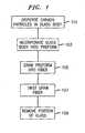
- FIG. 1 shows an exemplary process, in accordance with the principles of the invention, for assembling carbon particles, such as, carbon fibrils and carbon nanotube molecules, into aligned fibers using processes derived from the processes used to manufacture optical fiber.
- aligned it is meant that the axis along the longest dimension of each of the various particles in a local vicinity are substantially parallel.
- the process of FIG. 1 is entered, in step 101, when carbon particles are dispersed in a glass body.
- This may be achieved, in one embodiment of the invention, by forming an initial mixture through the dispersion of carbon particles, e.g., carbon nanotube molecules, carbon fibrils, or both in combination, within a sol-gel solution, which is a form of liquid glass. Thereafter, an ester is added to the mixture, causing it to solidify into the body, which may be porous. At this point the body may optionally be imbued with one or more other materials to influence the properties of the body so as to benefit the processing or the characteristics of the final fiber.
- a sol-gel solution which is a form of liquid glass.
- an ester is added to the mixture, causing it to solidify into the body, which may be porous.
- the body may optionally be imbued with one or more other materials to influence the properties of the body so as to benefit the processing or the characteristics of the final fiber.
- the body may then be heated to consolidate it, i.e., to remove some or all of the pores, if any, thereby forming a consolidated body.
- the heating may be performed in the presence of a gas, e.g., to keep oxygen away from the consolidated body.
- FIG. 2 shows exemplary consolidated glass body 201 with carbon particles 203 dispersed therein.
- the consolidated body 201 may be directly drawn into a fiber in step 105, the drawing step to be discussed further herein below. However, optionally, in step 103 the consolidated body may be incorporated into a preform, so that, advantageously, conventional glass fiber drawing equipment may be employed.
- consolidated glass body 201 is placed within a larger glass body with a hole in it, e.g., a piece of glass tubing, that can receive the consolidated body.
- multiple consolidated bodies may be placed within the larger glass body, provided that the larger glass body has multiple holes, at least one for each consolidated body. This is shown in FIG. 3 , where each of consolidated bodies 201 are placed within a respective hole 307 of larger glass body 305.
- the various consolidated bodies placed within a single larger glass body need not be the same.
- one consolidated body may contain carbon fibrils
- another may contain carbon nanotube molecules
- a third may contain a mixture of carbon fibrils and nanotube molecules.
- the larger glass body including the at least one consolidated body is then further consolidated, e.g., heated, so that the consolidated bodies are merged with the larger glass body into a single so-called "preform".
- step 105 the preform is then drawn, using conventional optical fiber techniques, into a glass fiber that has at least one aligned carbon particle fiber within it, e.g., one for each consolidated body that was placed within the larger glass body.
- FIG. 4 shows preform 309 in which the drawing process has started to produce therefrom aligned carbon particle fiber 407 within glass fiber 409.
- aligned it is meant the axis along the longest dimension of each the various carbon particles in a local vicinity are substantially parallel. This can be seen in FIG. 4 , where carbon particles closer to preform 309 than point 411 are randomly oriented while carbon particles within fiber 409 further from preform 309 than point 411 are pointing in substantially the same direction.
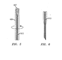
- the drawn glass fiber may be twisted.
- Such twisting causes the carbon nanotube fibers to be drawn toward the axis of the glass fiber, thereby expelling some of the glass between and within the carbon particles.
- the glass fiber may be reheated.
- the twisting of aligned carbon particle fibers 407 and the resulting combined twisted aligned carbon particle fiber 513 are shown in FIG. 5
- step 109 some or all of the glass coating the aligned carbon particle fibers may be removed, e.g., using chemical or mechanical processes, or a combination thereof. Also, glass between the combined twisted aligned carbon particle fibers may also be removed. The removal may be performed along the entire length of the fiber or only along a portion thereof.
- FIG. 6 shows combined twisted aligned carbon particle fiber 513 with a portion of the glass having been removed.
- the process produces fibers according to claims 18,19.
Landscapes
- Chemical & Material Sciences (AREA)
- Engineering & Computer Science (AREA)
- Materials Engineering (AREA)
- Organic Chemistry (AREA)
- Geochemistry & Mineralogy (AREA)
- Life Sciences & Earth Sciences (AREA)
- Manufacturing & Machinery (AREA)
- General Life Sciences & Earth Sciences (AREA)
- Nanotechnology (AREA)
- Chemical Kinetics & Catalysis (AREA)
- Dispersion Chemistry (AREA)
- General Chemical & Material Sciences (AREA)
- Condensed Matter Physics & Semiconductors (AREA)
- Physics & Mathematics (AREA)
- Crystallography & Structural Chemistry (AREA)
- General Physics & Mathematics (AREA)
- Ceramic Engineering (AREA)
- Composite Materials (AREA)
- Inorganic Chemistry (AREA)
- Power Engineering (AREA)
- Carbon And Carbon Compounds (AREA)
- Manufacture, Treatment Of Glass Fibers (AREA)
- Inorganic Fibers (AREA)
- Solid-Sorbent Or Filter-Aiding Compositions (AREA)
- Glass Compositions (AREA)
Claims (19)
- Verfahren zum Aggregieren von Kohlenstoff-Partikeln zu mindestens einer ausgerichtete Kohlenstoff-Partikel enthaltenden Faser, wobei das Verfahren den Schritt des Ziehens von Glas, welches die besagten Kohlenstoff-Partikel enthält, umfasst, um aus den besagten Kohlenstoff-Partikeln mindestens eine Kohlenstoff-Partikel enthaltende Faser zu fertigen.
- Erfindung nach Anspruch 1, wobei die besagten Kohlenstoff-Partikel (i) Kohlenstoff-Nanoröhrchen-Moleküle und (ii) Kohlenstoff-Fibrillen sind.
- Erfindung nach Anspruch 1, weiterhin umfassend den Schritt des Verdrillens der besagten Faser.
- Erfindung nach Anspruch 1, weiterhin umfassend den Schritt des Verdrillens der besagten Kohlenstoff-Faser unter Erwärmen der besagten Faser, um das Verdrillen zu erleichtern.
- Erfindung nach Anspruch 1, weiterhin umfassend den Schritt des Erwärmens des besagten Kohlenstoff-Partikel enthaltenden Glases, während es gezogen wird.
- Erfindung nach Anspruch 1, wobei der besagte Schritt des Ziehens einer Vielzahl von ausgerichtete Kohlenstoff-Partikel enthaltenden Fasern erzeugt, wobei das Verfahren weiterhin den Schritt des Verdrillens der besagten Vielzahl von Fasern umfasst, wobei die besagten ausgerichtete Kohlenstoff-Partikel enthaltenden Fasern in Richtung der Achse der besagten Faser gezogen werden, um zwischen und in den besagten Kohlenstoff-Partikel enthaltenden Fasern vorhandenes Glas vor Durchführen der Verdrillung auszustoßen.
- Erfindung nach Anspruch 1, weiterhin umfassend den Schritt des Formens des besagten Kohlenstoff-Partikel enthaltenden Glases.
- Erfindung nach Anspruch 7, wobei der besagte Schritt des Formens weiterhin den Schritt des Verfestigens des Gemischs der Kohlenstoff-Partikel in einer Sol-Gel-Lösung umfasst, wodurch ein Körper geformt wird.
- Erfindung nach Anspruch 8, wobei der besagte Schritt des Formens weiterhin den Schritt des Dispergierens von Kohlenstoff-Partikeln in der besagten Sol-Gel-Lösung umfasst, um das besagte Gemisch zu formen.
- Erfindung nach Anspruch 8, wobei der besagte Schritt des Verfestigens weiterhin den Schritt des Hinzufügens eines Esters zu dem besagten Gemisch umfasst.
- Erfindung nach Anspruch 8, wobei der besagte Körper porös ist.
- Erfindung nach Anspruch 8, weiterhin umfassend den Schritt des Tränkens des besagten Körpers mit mindestens einem anderen Material.
- Erfindung nach Anspruch 8, weiterhin umfassend den Schritt des Erwärmens der besagten Vorform, um diese zu konsolidieren, wodurch ein konsolidierter Körper entsteht.
- Erfindung nach Anspruch 8, weiterhin umfassend den Schritt des Einbettens des besagten Körpers in einen größeren Körper, um eine Vorform zu formen.
- Erfindung nach Anspruch 14, wobei der besagte Schritt des Einbettens weiterhin den Schritt des Erwärmens des besagten größeren Körpers umfasst, um diesen zu konsolidieren.
- Erfindung nach Anspruch 14, weiterhin umfassend den Schritt des Einbettens mindestens eines anderen Körpers in den besagten größeren Körper, so dass die besagte Vorform mehrere Körper enthält.
- Erfindung nach Anspruch 1, weiterhin umfassend den Schritt des Abziehens von etwas Glas aus der besagten Faser.
- Kohlenstoff-Partikel enthaltende Faser mit ausgerichteten Kohlenstoff-Partikel, welche durch das Ziehen während der Dispersion im Glas ausgerichtet wurden.
- Erfindung nach Anspruch 18, wobei die besagten Kohlenstoff-Partikel (i) Kohlenstoff-Nanoröhrchen-Moleküle, und (ii) Kohlenstoff-Fibrillen sind
Applications Claiming Priority (2)
| Application Number | Priority Date | Filing Date | Title |
|---|---|---|---|
| US789074 | 2004-02-27 | ||
| US10/789,074 US7628041B2 (en) | 2004-02-27 | 2004-02-27 | Carbon particle fiber assembly technique |
Publications (2)
| Publication Number | Publication Date |
|---|---|
| EP1568664A1 EP1568664A1 (de) | 2005-08-31 |
| EP1568664B1 true EP1568664B1 (de) | 2013-07-10 |
Family
ID=34750547
Family Applications (1)
| Application Number | Title | Priority Date | Filing Date |
|---|---|---|---|
| EP05250871.0A Expired - Lifetime EP1568664B1 (de) | 2004-02-27 | 2005-02-15 | Kohlenstoff-Partikel enthaltende Glasfasern |
Country Status (5)
| Country | Link |
|---|---|
| US (1) | US7628041B2 (de) |
| EP (1) | EP1568664B1 (de) |
| JP (1) | JP4928084B2 (de) |
| KR (1) | KR101177122B1 (de) |
| CN (2) | CN104609721A (de) |
Families Citing this family (37)
| Publication number | Priority date | Publication date | Assignee | Title |
|---|---|---|---|---|
| US7399443B2 (en) * | 2004-02-27 | 2008-07-15 | Lucent Technologies Inc. | Carbon particle fiber assembly technique |
| AU2006301936B8 (en) * | 2005-10-12 | 2013-07-18 | Adelaide Research & Innovation Pty Ltd | Fabrication of nanowires |
| WO2008060336A2 (en) * | 2006-06-09 | 2008-05-22 | Cleveland State University | High strength composite materials and related processes |
| US9005755B2 (en) | 2007-01-03 | 2015-04-14 | Applied Nanostructured Solutions, Llc | CNS-infused carbon nanomaterials and process therefor |
| US8158217B2 (en) | 2007-01-03 | 2012-04-17 | Applied Nanostructured Solutions, Llc | CNT-infused fiber and method therefor |
| US8951632B2 (en) | 2007-01-03 | 2015-02-10 | Applied Nanostructured Solutions, Llc | CNT-infused carbon fiber materials and process therefor |
| US8951631B2 (en) | 2007-01-03 | 2015-02-10 | Applied Nanostructured Solutions, Llc | CNT-infused metal fiber materials and process therefor |
| CN102317200B (zh) | 2009-02-17 | 2014-04-09 | 应用纳米结构方案公司 | 包括纤维上的碳纳米管的复合材料 |
| CA2752525C (en) | 2009-02-27 | 2017-05-16 | Applied Nanostructured Solutions, Llc | Low temperature cnt growth using gas-preheat method |
| US20100224129A1 (en) | 2009-03-03 | 2010-09-09 | Lockheed Martin Corporation | System and method for surface treatment and barrier coating of fibers for in situ cnt growth |
| US9111658B2 (en) | 2009-04-24 | 2015-08-18 | Applied Nanostructured Solutions, Llc | CNS-shielded wires |
| KR20120017034A (ko) | 2009-04-24 | 2012-02-27 | 어플라이드 나노스트럭처드 솔루션스, 엘엘씨. | Cnt 기반 시그니처 제어 물질 |
| CA2760144A1 (en) | 2009-04-27 | 2010-11-11 | Applied Nanostructured Solutions, Llc | Cnt-based resistive heating for deicing composite structures |
| WO2010141914A2 (en) | 2009-06-05 | 2010-12-09 | Mccutchen Co. | Reactors for forming foam materials from high internal phase emulsions, methods of forming foam materials and conductive nanostructures therein |
| EP2461953A4 (de) | 2009-08-03 | 2014-05-07 | Applied Nanostructured Sols | Einsatz von nanopartikeln in verbundfasern |
| US8101913B2 (en) * | 2009-09-11 | 2012-01-24 | Ut-Battelle, Llc | Method of making large area conformable shape structures for detector/sensor applications using glass drawing technique and postprocessing |
| US20110124253A1 (en) * | 2009-11-23 | 2011-05-26 | Applied Nanostructured Solutions, Llc | Cnt-infused fibers in carbon-carbon composites |
| KR20120117978A (ko) | 2009-11-23 | 2012-10-25 | 어플라이드 나노스트럭처드 솔루션스, 엘엘씨. | 카본 나노튜브-주입된 섬유 재료를 포함하는 세라믹 복합재료 및 이의 제조방법 |
| US8662449B2 (en) | 2009-11-23 | 2014-03-04 | Applied Nanostructured Solutions, Llc | CNT-tailored composite air-based structures |
| CN103079805B (zh) | 2009-12-14 | 2015-02-11 | 应用纳米结构方案公司 | 含有碳纳米管并入的纤维材料的防火复合材料和制品 |
| US9167736B2 (en) | 2010-01-15 | 2015-10-20 | Applied Nanostructured Solutions, Llc | CNT-infused fiber as a self shielding wire for enhanced power transmission line |
| JP5830471B2 (ja) | 2010-02-02 | 2015-12-09 | アプライド ナノストラクチャード ソリューションズ リミテッド ライアビリティー カンパニーApplied Nanostructuredsolutions, Llc | 平行に配列されたカーボン・ナノチューブを含むカーボン・ナノチューブ導入繊維材料の生産方法 |
| EP2543099A4 (de) | 2010-03-02 | 2018-03-28 | Applied NanoStructured Solutions, LLC | Spiralförmig gewundene elektrische vorrichtung mit kohlenstoffnanoröhrchen-infundierten elektrodenmaterialien sowie verfahren und vorrichtungen zu ihrer herstellung |
| AU2011223743A1 (en) | 2010-03-02 | 2012-08-30 | Applied Nanostructured Solutions,Llc | Electrical devices containing carbon nanotube-infused fibers and methods for production thereof |
| US8051682B1 (en) * | 2010-06-01 | 2011-11-08 | The Boeing Company | Apparatus and method for making glass preform with nanofiber reinforcement |
| US8780526B2 (en) | 2010-06-15 | 2014-07-15 | Applied Nanostructured Solutions, Llc | Electrical devices containing carbon nanotube-infused fibers and methods for production thereof |
| US9017854B2 (en) | 2010-08-30 | 2015-04-28 | Applied Nanostructured Solutions, Llc | Structural energy storage assemblies and methods for production thereof |
| CN103097039A (zh) | 2010-09-14 | 2013-05-08 | 应用奈米结构公司 | 长有碳纳米管玻璃基板及其制造方法 |
| CA2809285A1 (en) | 2010-09-22 | 2012-03-29 | Applied Nanostructured Solutions, Llc | Carbon fiber substrates having carbon nanotubes grown thereon and processes for production thereof |
| AU2011305751A1 (en) | 2010-09-23 | 2012-06-21 | Applied Nanostructured Solutions, Llc | CNT-infused fiber as a self shielding wire for enhanced power transmission line |
| US9085464B2 (en) | 2012-03-07 | 2015-07-21 | Applied Nanostructured Solutions, Llc | Resistance measurement system and method of using the same |
| KR101376139B1 (ko) | 2012-08-07 | 2014-03-19 | 포항공과대학교 산학협력단 | 탄소나노튜브 섬유사 제조방법 및 장치 |
| WO2014123532A1 (en) * | 2013-02-08 | 2014-08-14 | United States Of America, As Represented By The Administrator Of The National Aeronautics And Space Administration | High strength nanocomposite glass fibers |
| US20150004392A1 (en) * | 2013-06-28 | 2015-01-01 | The Boeing Company | Whisker-reinforced hybrid fiber by method of base material infusion into whisker yarn |
| CN112203819A (zh) * | 2018-05-31 | 2021-01-08 | 琳得科株式会社 | 碳树脂复合材料的制造方法及碳树脂复合材料的制造用复合结构体 |
| JP7441799B2 (ja) * | 2018-12-27 | 2024-03-01 | 住友電気工業株式会社 | カーボンナノチューブの製造方法、カーボンナノチューブ集合線の製造方法、カーボンナノチューブ集合線バンドルの製造方法、カーボンナノチューブ製造装置、カーボンナノチューブ集合線製造装置及びカーボンナノチューブ集合線バンドル製造装置 |
| DE102020107743A1 (de) | 2020-03-20 | 2021-09-23 | Karlsruher Institut für Technologie (Körperschaft des öffentlichen Rechts) | Hybridfaser und Verfahren zu ihrer Herstellung |
Family Cites Families (19)
| Publication number | Priority date | Publication date | Assignee | Title |
|---|---|---|---|---|
| GB1174959A (en) | 1966-09-16 | 1969-12-17 | Carborundum Co | Whisker Orientation and Shaped Bodies containing Uniaxially Oriented Whiskers |
| ES367287A1 (es) * | 1968-05-16 | 1971-06-16 | Atomic Energy Authority Uk | Procedimiento para producir un material compuesto. |
| DE3516920C2 (de) | 1985-05-10 | 1986-09-25 | Erwin Prof. Dr.-Ing. 6750 Kaiserslautern Roeder | Verfahren und Vorrichtung zur Herstellung von faserverstärkten Stangen oder Profilen aus anorganischen Gläsern oder aus Gläsern, die in eine Glaskeramik überführt werden können, deren Kernzone unidirektional mit kontinuierlichen Fasern verstärkt ist |
| JPS62246835A (ja) * | 1986-04-18 | 1987-10-28 | Seiko Epson Corp | 石英ガラス系光フアイバ用母材の製造方法 |
| US4820664A (en) * | 1987-01-20 | 1989-04-11 | Clemson University | Piggy back method for producing ceramic fibers and non-circular ceramic fibers in particular |
| JP2862578B2 (ja) * | 1989-08-14 | 1999-03-03 | ハイピリオン・カタリシス・インターナシヨナル・インコーポレイテツド | 樹脂組成物 |
| US5240488A (en) * | 1992-08-14 | 1993-08-31 | At&T Bell Laboratories | Manufacture of vitreous silica product via a sol-gel process using a polymer additive |
| US6683783B1 (en) * | 1997-03-07 | 2004-01-27 | William Marsh Rice University | Carbon fibers formed from single-wall carbon nanotubes |
| EP1054036A1 (de) * | 1999-05-18 | 2000-11-22 | Fina Research S.A. | Verstärkte Polymere |
| US6299812B1 (en) * | 1999-08-16 | 2001-10-09 | The Board Of Regents Of The University Of Oklahoma | Method for forming a fibers/composite material having an anisotropic structure |
| US6682677B2 (en) * | 2000-11-03 | 2004-01-27 | Honeywell International Inc. | Spinning, processing, and applications of carbon nanotube filaments, ribbons, and yarns |
| JP4959093B2 (ja) * | 2002-01-07 | 2012-06-20 | 雄一郎 仁科 | 石英−クラッド・カーボンナノチューブファイバー束の製造法 |
| AU2003202949A1 (en) * | 2002-01-11 | 2003-07-30 | Ali Alwattari | Methods and apparatus for spinning spider silk protein |
| US6934600B2 (en) * | 2002-03-14 | 2005-08-23 | Auburn University | Nanotube fiber reinforced composite materials and method of producing fiber reinforced composites |
| US6852410B2 (en) * | 2002-07-01 | 2005-02-08 | Georgia Tech Research Corporation | Macroscopic fiber comprising single-wall carbon nanotubes and acrylonitrile-based polymer and process for making the same |
| US20060099135A1 (en) * | 2002-09-10 | 2006-05-11 | Yodh Arjun G | Carbon nanotubes: high solids dispersions and nematic gels thereof |
| US20050061496A1 (en) * | 2003-09-24 | 2005-03-24 | Matabayas James Christopher | Thermal interface material with aligned carbon nanotubes |
| US20050228110A1 (en) * | 2003-12-24 | 2005-10-13 | Ko Frank K | Continuous organic and inorganic matrix composite fibrils and methods for their production from carbon nanotubes |
| US7803262B2 (en) * | 2004-04-23 | 2010-09-28 | Florida State University Research Foundation | Alignment of carbon nanotubes using magnetic particles |
-
2004
- 2004-02-27 US US10/789,074 patent/US7628041B2/en active Active
-
2005
- 2005-02-15 EP EP05250871.0A patent/EP1568664B1/de not_active Expired - Lifetime
- 2005-02-25 KR KR1020050015750A patent/KR101177122B1/ko not_active Expired - Fee Related
- 2005-02-25 CN CN201410795926.4A patent/CN104609721A/zh active Pending
- 2005-02-25 CN CN2005100524224A patent/CN1660710A/zh active Pending
- 2005-02-25 JP JP2005050010A patent/JP4928084B2/ja not_active Expired - Fee Related
Also Published As
| Publication number | Publication date |
|---|---|
| KR20060042216A (ko) | 2006-05-12 |
| EP1568664A1 (de) | 2005-08-31 |
| US20050188727A1 (en) | 2005-09-01 |
| CN104609721A (zh) | 2015-05-13 |
| JP2005240270A (ja) | 2005-09-08 |
| CN1660710A (zh) | 2005-08-31 |
| US7628041B2 (en) | 2009-12-08 |
| KR101177122B1 (ko) | 2012-08-24 |
| JP4928084B2 (ja) | 2012-05-09 |
Similar Documents
| Publication | Publication Date | Title |
|---|---|---|
| EP1568664B1 (de) | Kohlenstoff-Partikel enthaltende Glasfasern | |
| Lu et al. | Interfacial adhesion of plasma‐treated carbon fiber/poly (phthalazinone ether sulfone ketone) composite | |
| US8058364B2 (en) | Method for functionalization of nanoscale fibers and nanoscale fiber films | |
| EA200702132A1 (ru) | Текстильный материал, содержащий по меньшей мере один слой полимерных нановолокон, и способ изготовления слоя полимерных нановолокон из полимерного раствора методом электростатического формования волокна | |
| US20060093290A1 (en) | Etched tapered fiber bundle and method of making the same | |
| CN112252022B (zh) | 一种超亲水pps复合纤维膜的制备方法 | |
| Kim et al. | Facile method to enhance the mechanical interfacial strength between carbon fibers and polyamide 6 using modified silane coupling agents | |
| Itankar et al. | Eu3+‐doped polystyrene and polyvinylidene fluoride nanofibers made by electrospinning for photoluminescent fabric designing | |
| JP6010519B2 (ja) | マルチコアファイバ | |
| Lee et al. | Novel composite layer based on electrospun polymer nanofibers for efficient light scattering | |
| WO2019156295A1 (ko) | 자기장 및 전기장을 이용한 친환경 고강도 나노셀룰로오스 장섬유 제조 방법 | |
| JP2010037667A (ja) | 炭素繊維ウェブの製造方法および炭素繊維ウェブ | |
| CN105261722A (zh) | 取向改性纤维同质增强含氟树脂基隔膜 | |
| US7399443B2 (en) | Carbon particle fiber assembly technique | |
| CN102890312A (zh) | 大模场光纤泵浦耦合器及其制造方法 | |
| JP2008026903A (ja) | クリンプおよびクリーブコネクタ用の拡張帯域光ファイバ | |
| JP6119321B2 (ja) | 繊維強化複合材料 | |
| CN107515472A (zh) | 新型多模泵浦光纤合束器及其制造方法 | |
| CN1211674C (zh) | 光衰减器 | |
| JP2013071848A (ja) | 断熱材 | |
| KR102184470B1 (ko) | 복합재 | |
| Asghari Arpatappeh et al. | Morphology evolution of self‐same nanocomposites hybridized with jumbo‐sized particles | |
| US20150277033A1 (en) | Optical fiber with a low-index core and a core grating | |
| Li et al. | Effect of improved electric field distribution on jet motion, fiber morphology, and properties of electrospun thermoplastic polyurethane fibrous membrane | |
| US9658408B2 (en) | Reinforced optical fiber cable |
Legal Events
| Date | Code | Title | Description |
|---|---|---|---|
| PUAI | Public reference made under article 153(3) epc to a published international application that has entered the european phase |
Free format text: ORIGINAL CODE: 0009012 |
|
| 17P | Request for examination filed |
Effective date: 20050310 |
|
| AK | Designated contracting states |
Kind code of ref document: A1 Designated state(s): AT BE BG CH CY CZ DE DK EE ES FI FR GB GR HU IE IS IT LI LT LU MC NL PL PT RO SE SI SK TR |
|
| AX | Request for extension of the european patent |
Extension state: AL BA HR LV MK YU |
|
| AKX | Designation fees paid |
Designated state(s): DE FR GB |
|
| 17Q | First examination report despatched |
Effective date: 20050726 |
|
| APBN | Date of receipt of notice of appeal recorded |
Free format text: ORIGINAL CODE: EPIDOSNNOA2E |
|
| APBR | Date of receipt of statement of grounds of appeal recorded |
Free format text: ORIGINAL CODE: EPIDOSNNOA3E |
|
| APAV | Appeal reference deleted |
Free format text: ORIGINAL CODE: EPIDOSDREFNE |
|
| APBT | Appeal procedure closed |
Free format text: ORIGINAL CODE: EPIDOSNNOA9E |
|
| RAP3 | Party data changed (applicant data changed or rights of an application transferred) |
Owner name: LUCENT TECHNOLOGIES INC. |
|
| GRAP | Despatch of communication of intention to grant a patent |
Free format text: ORIGINAL CODE: EPIDOSNIGR1 |
|
| GRAP | Despatch of communication of intention to grant a patent |
Free format text: ORIGINAL CODE: EPIDOSNIGR1 |
|
| RAP1 | Party data changed (applicant data changed or rights of an application transferred) |
Owner name: ALCATEL-LUCENT USA INC. |
|
| GRAS | Grant fee paid |
Free format text: ORIGINAL CODE: EPIDOSNIGR3 |
|
| GRAA | (expected) grant |
Free format text: ORIGINAL CODE: 0009210 |
|
| AK | Designated contracting states |
Kind code of ref document: B1 Designated state(s): DE FR GB |
|
| REG | Reference to a national code |
Ref country code: GB Ref legal event code: FG4D |
|
| REG | Reference to a national code |
Ref country code: DE Ref legal event code: R096 Ref document number: 602005040319 Country of ref document: DE Effective date: 20130905 |
|
| 111Z | Information provided on other rights and legal means of execution |
Free format text: DE FR GB Effective date: 20130410 |
|
| REG | Reference to a national code |
Ref country code: FR Ref legal event code: GC Effective date: 20131112 |
|
| REG | Reference to a national code |
Ref country code: GB Ref legal event code: 732E Free format text: REGISTERED BETWEEN 20131212 AND 20131218 |
|
| PLBE | No opposition filed within time limit |
Free format text: ORIGINAL CODE: 0009261 |
|
| STAA | Information on the status of an ep patent application or granted ep patent |
Free format text: STATUS: NO OPPOSITION FILED WITHIN TIME LIMIT |
|
| 26N | No opposition filed |
Effective date: 20140411 |
|
| REG | Reference to a national code |
Ref country code: DE Ref legal event code: R097 Ref document number: 602005040319 Country of ref document: DE Effective date: 20140411 |
|
| REG | Reference to a national code |
Ref country code: FR Ref legal event code: RG Effective date: 20141015 |
|
| REG | Reference to a national code |
Ref country code: FR Ref legal event code: PLFP Year of fee payment: 11 |
|
| REG | Reference to a national code |
Ref country code: FR Ref legal event code: PLFP Year of fee payment: 12 |
|
| REG | Reference to a national code |
Ref country code: FR Ref legal event code: PLFP Year of fee payment: 13 |
|
| REG | Reference to a national code |
Ref country code: FR Ref legal event code: PLFP Year of fee payment: 14 |
|
| PGFP | Annual fee paid to national office [announced via postgrant information from national office to epo] |
Ref country code: FR Payment date: 20190111 Year of fee payment: 15 Ref country code: GB Payment date: 20190213 Year of fee payment: 15 Ref country code: DE Payment date: 20190205 Year of fee payment: 15 |
|
| REG | Reference to a national code |
Ref country code: DE Ref legal event code: R119 Ref document number: 602005040319 Country of ref document: DE |
|
| GBPC | Gb: european patent ceased through non-payment of renewal fee |
Effective date: 20200215 |
|
| PG25 | Lapsed in a contracting state [announced via postgrant information from national office to epo] |
Ref country code: FR Free format text: LAPSE BECAUSE OF NON-PAYMENT OF DUE FEES Effective date: 20200229 Ref country code: DE Free format text: LAPSE BECAUSE OF NON-PAYMENT OF DUE FEES Effective date: 20200901 Ref country code: GB Free format text: LAPSE BECAUSE OF NON-PAYMENT OF DUE FEES Effective date: 20200215 |