EP1568600A1 - Dispositif et procédé d'ancrage d'une embase sur une paroi au fond de la mer - Google Patents
Dispositif et procédé d'ancrage d'une embase sur une paroi au fond de la mer Download PDFInfo
- Publication number
- EP1568600A1 EP1568600A1 EP04358002A EP04358002A EP1568600A1 EP 1568600 A1 EP1568600 A1 EP 1568600A1 EP 04358002 A EP04358002 A EP 04358002A EP 04358002 A EP04358002 A EP 04358002A EP 1568600 A1 EP1568600 A1 EP 1568600A1
- Authority
- EP
- European Patent Office
- Prior art keywords
- wall
- base
- bolts
- orifices
- orifice
- Prior art date
- Legal status (The legal status is an assumption and is not a legal conclusion. Google has not performed a legal analysis and makes no representation as to the accuracy of the status listed.)
- Granted
Links
Images


Classifications
-
- E—FIXED CONSTRUCTIONS
- E02—HYDRAULIC ENGINEERING; FOUNDATIONS; SOIL SHIFTING
- E02B—HYDRAULIC ENGINEERING
- E02B15/00—Cleaning or keeping clear the surface of open water; Apparatus therefor
- E02B15/04—Devices for cleaning or keeping clear the surface of open water from oil or like floating materials by separating or removing these materials
- E02B15/08—Devices for reducing the polluted area with or without additional devices for removing the material
-
- B—PERFORMING OPERATIONS; TRANSPORTING
- B63—SHIPS OR OTHER WATERBORNE VESSELS; RELATED EQUIPMENT
- B63B—SHIPS OR OTHER WATERBORNE VESSELS; EQUIPMENT FOR SHIPPING
- B63B27/00—Arrangement of ship-based loading or unloading equipment for cargo or passengers
- B63B27/08—Arrangement of ship-based loading or unloading equipment for cargo or passengers of winches
-
- B—PERFORMING OPERATIONS; TRANSPORTING
- B63—SHIPS OR OTHER WATERBORNE VESSELS; RELATED EQUIPMENT
- B63C—LAUNCHING, HAULING-OUT, OR DRY-DOCKING OF VESSELS; LIFE-SAVING IN WATER; EQUIPMENT FOR DWELLING OR WORKING UNDER WATER; MEANS FOR SALVAGING OR SEARCHING FOR UNDERWATER OBJECTS
- B63C7/00—Salvaging of disabled, stranded, or sunken vessels; Salvaging of vessel parts or furnishings, e.g. of safes; Salvaging of other underwater objects
- B63C7/006—Emptying the contents of sunken, stranded, or disabled vessels, e.g. by engaging the vessel; Underwater collecting of buoyant contents, such as liquid, particulate or gaseous contents, escaping from sunken vessels, e.g. using funnels, or tents for recovery of escaping hydrocarbons
-
- E—FIXED CONSTRUCTIONS
- E21—EARTH DRILLING; MINING
- E21B—EARTH DRILLING, e.g. DEEP DRILLING; OBTAINING OIL, GAS, WATER, SOLUBLE OR MELTABLE MATERIALS OR A SLURRY OF MINERALS FROM WELLS
- E21B41/00—Equipment or details not covered by groups E21B15/00 - E21B40/00
- E21B41/08—Underwater guide bases, e.g. drilling templates; Levelling thereof
-
- E—FIXED CONSTRUCTIONS
- E21—EARTH DRILLING; MINING
- E21B—EARTH DRILLING, e.g. DEEP DRILLING; OBTAINING OIL, GAS, WATER, SOLUBLE OR MELTABLE MATERIALS OR A SLURRY OF MINERALS FROM WELLS
- E21B43/00—Methods or apparatus for obtaining oil, gas, water, soluble or meltable materials or a slurry of minerals from wells
- E21B43/01—Methods or apparatus for obtaining oil, gas, water, soluble or meltable materials or a slurry of minerals from wells specially adapted for obtaining from underwater installations
- E21B43/0122—Collecting oil or the like from a submerged leakage
-
- E—FIXED CONSTRUCTIONS
- E21—EARTH DRILLING; MINING
- E21B—EARTH DRILLING, e.g. DEEP DRILLING; OBTAINING OIL, GAS, WATER, SOLUBLE OR MELTABLE MATERIALS OR A SLURRY OF MINERALS FROM WELLS
- E21B7/00—Special methods or apparatus for drilling
- E21B7/12—Underwater drilling
- E21B7/124—Underwater drilling with underwater tool drive prime mover, e.g. portable drilling rigs for use on underwater floors
-
- E—FIXED CONSTRUCTIONS
- E02—HYDRAULIC ENGINEERING; FOUNDATIONS; SOIL SHIFTING
- E02B—HYDRAULIC ENGINEERING
- E02B15/00—Cleaning or keeping clear the surface of open water; Apparatus therefor
- E02B2015/005—Tent-like structures for dealing with pollutant emissions below the water surface
Definitions
- the subject of the present invention is a device and a method installation and anchoring of a base on a wall at the bottom of the sea.
- It may be, in particular, a wall, a ship failed or a tank of a ship stranded on which one wishes to intervene.
- said base can be part of a module carrying various functions such as lifting connection means or assembly means for performing various operations at said wall after anchoring thereof on the wall.
- Said base may, more particularly, be used for anchoring a any device, including a shuttle tank to collect a fluid of a tank on the wall of which said base is anchored as it will be explained below.
- the present invention also relates to a device and a method of installing and anchoring a base on a wall at the bottom of the sea and, if necessary, piercing said wall, in particular to recover, let a fluid pass through the orifice thus created on said wall.
- This last type of device and process is particularly useful when it is desired to implement a method and an installation of recovery of effluents at sea and more particularly effluents pollutants contained in a sunken and damaged ship lying at the bottom of the sea.
- the ship During the sinking of oil tankers, the ship usually sinks after having been deeply damaged and having lost part of his cargo.
- the depth of water is important, for example 100 or 200 meters, the recovery of the wreck or its bailout, is in not considered, but the hull must be completely emptied and rinsed, so that the corrosion of the structure over time, creating localized or generalized holes, does not lead to the release of the contents of the ship, creating a pollution that can last for years, even decades.
- said receptacle consists of a bell whose open base constitutes said lower orifice and covers a leakage zone of said effluents, said zone comprising one or more openings in the shell and / or the vessel said vessel, and means for anchoring said receptacle on the vessel comprising cables connecting attachment points fixed on the periphery of said receptacle base and attachment points on the vessel.
- said receptacle consists of a rigid container of substantially tubular, which is held upright by means of floats installed at least at the top end or at each top end and bottom of said container, said upper and lower orifices of said container being closable so that said receptacle can be reassembled on the surface and installed in a floating horizontal position when ports are closed, said receptacle can then be towed to a installation or a storage vessel of said effluents.
- shuttle tanks have been described in the European patent applications EP 03 358 003.6 and EP 03 358 019.2.
- the shuttle tank is anchored directly on the wall of the tank.
- Hot tap load-bearing tappings
- This device is effective for fasteners that do not require low tensile strength and therefore low restraining force and can be effective only if the wall crossed is of good quality and thick enough to create a thread, which is often not the case of shipwrecks, whose sinking is often due to a great dilapidation or a flagrant lack of maintenance.
- the means for piercing the wall and anchoring thereto, with a view to fixing said second module consist of a system similar drill / tap as described in US 3,831,387 giving a limited restraint, especially in the case of wreckage in poor condition.
- An object of the present invention is to provide device and drilling process and fixing a base on a wall at the bottom of the which are more mechanically reliable and simpler to carry out and implement, particularly at great depth, and in particular in conditions of use requiring a strong resistance to mechanical pulls that can undergo said base anchored on said wall a wreck in very bad state of maintenance.
- the diameter of the piercing of the shell allowing to evacuate said cargo is of small diameter, for example from 100mm to 300mm, and transfer lines to the surface of a similar diameter, coupled to pumping means, are then generally sufficient.
- the quilting device must have a very small diameter important and the hull piercing machine must be able to drill a hole corresponding to said passage diameter, that is to say 700 to 800mm, see more. It must therefore be extremely powerful and be firmly attached to the shell to stay in place without moving or vibrate throughout the drilling phase.
- the latter when filling the shuttle, the latter is positioned vertically from the opening of the shell, and is advantageously fixed by a cable to said device stitching, which represents a significant traction.
- the shuttle when the shuttle is full, because of the density difference between seawater and crude oil, it exerts a vertical thrust that can reach 20 to 30 tons for a 300m 3 shuttle; this vertical thrust generates an upward vertical pull in said cable connected to said stitching device, as well as in the fastening means of said stitching device on the hull of the wreck.
- Another object of the present invention is to provide a system of fluid recovery from the bottom of the sea without implementing pumping means. More particularly, an object of the present invention is to provide a method and an installation for recovering the the contents of the berths of a ship, for example an oil tanker, based on the seabed, in deep water depths, especially greater than 3000 meters, or even 4000 to 5000 meters, and which present the disadvantages of prior methods and devices and, in particular, who are more technically reliable, more comfortable and enforce.
- Longitudinal sliding means a displacement in the longitudinal direction, which can be doubled by one rotation per relative to the longitudinal axis.
- Buoyancy elements can be incorporated into the device for installing and anchoring a base according to the invention to control its buoyancy, especially when descending to the bottom of the sea since the surface, to perform this in hydrostatic equilibrium, but also to the moment of approach and installation of the device according to the invention against wall to be drilled.
- This approach and pose can be done using an outside operator and, in particular, by means of a vehicle submarine controlled remotely, especially from the surface, of the type ROV ("Remotely Operated Vehicle"), in particular if it is necessary to incline the device according to the invention for its anchoring on a wall strongly slanted, or on a vertical wall.
- ROV Remotely Operated Vehicle
- the reversible connection means between the base and the structure may be hooks released by an underwater vehicle controlled remotely, especially from the surface (ROV), or by hydraulic or mechanical cylinders operated by said ROV.
- ROV surface
- a major advantage of the anchoring system according to the invention is to avoid the creation of a thread in said second wall orifices which we do not know the mechanical performances which can be particularly affected by corosion.
- Said bolts can be driven in rotation directly by a motor or preferably via a device itself rotated such as training guns.
- said first means of automatic restraint system comprise first retaining elements suitable for be constrained or retracted by means of second retaining elements for allow them to pass through said first and second ports, and said first automatic retaining elements are capable of being released in the extended position or deployed automatically after through said second orifices in said wall, so as to ensure a retaining the wall and its anchoring by clamping between said nuts and said first retainers when the bolts are actuated in rotation and sliding in the opposite direction from inside to outside of said wall.
- said first retaining means are formed by segments in the form of open rings able to be inserted in force by their elasticity in grooves with the lower end of said bolts above said first means of section, said segments being held in said grooves by circumferential rings applied against the external surface of the bolts at level of said segments, preferably sliding with reduced clearance, such so that said peripheral rings, by their diameter more important than that of said second orifices, are retained by the face upper wall after drilling said second orifices, and are suitable to thus release said segments in partially elastic radial extension out of said grooves in which they remain blocked after passing through longitudinal sliding through said second holes of the wall, said segments in partial radial extension preventing their passage into reverse direction through the wall and thus allowing the wall to be clamped by the bolts between said nut and said extension segment by sliding in the opposite direction of said bolts resulting from their rotation.
- the diameter of the lower cylindrical end said bolts may have a diameter dimensioned at will and hence the diameter of said extended segments is such that their restraint mechanically by the inner face of the wall is able to withstand a substantial tens of tons of tensile pulling upwards on said base after anchoring thereof on the wall.
- said base comprises a first large cylindrical central axis port in the said direction longitudinal ZZ ', in particular a first large orifice of at least 300 mm, more particularly from 300 to 1500 mm, more particularly 500 at 800 mm.
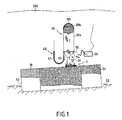
- FIGS 1 to 8 and 10 there is shown a base 2 consisting of in a flat platform anchored to the upper wall 1b of a tank 53 containing a thick fluid consisting of a polluting effluent 51, said tank resting at the bottom of the sea 52.
- a shuttle tank 30 is anchored on the base 2 to recover said fluid escaping and being reassembled in surface 500 as described in more detail below.
- Said base comprises a large central orifice 13 cylindrical allowing the evacuation of said thick fluid by going up through said large orifice 13 by its density lighter than seawater.
- FIGS. 2, 6a, 6b, 6c and 8 show a device for installing and anchoring said base capable of drilling a large central orifice 26 in said wall, so as to allow discharging said thick fluid 51 from the vessel 53 through said orifice.
- Said base comprises hooks 3 that can be actuated by a external operator such as a ROV 50 to separate it from the structure upper 3 after inking the base 2 on the wall 1b.
- the upper structure 4 consists of a welded frame parallelepiped comprising longitudinal guide rails 4a along from which four carriages 4b can slide respectively along from which can slide in a longitudinal direction ZZ ', trolleys 4b.
- the welded frame 4 supports within it a main body of drilling 17 fixed relative to said frame and supporting at its base seconds cutting means 14, consisting of a hole saw or bit adapted to perform circular perforations with a diameter of at least 300 mm, plus particularly from 300 to 1500 mm, more particularly from 500 to 800 mm, corresponding to said second large central orifice in the wall 1b.
- Said main body 17 encloses an actuating motor in rotation 17a (not visible) and a cylinder 16 allowing the sliding longitudinal in the direction ZZ 'relative to said second cutting means 14 in relation to said main body 17.
- the lateral carriages 4b support four anchor bolts 5 of which the structure and operation are explained below.
- the carriages 4b are actuated in longitudinal sliding in the direction ZZ 'along the rails 4a by cylinders 7 fixedly mounted on said rails 4a.
- Anchor bolts consist of cylindrical rods threaded.
- the carriages 4b support training guns 6 capable of being rotated by motors 8b, also supported by said trolleys 4b.
- the guns 6 comprise cylindrical hollow housing longitudinal axis in the direction ZZ 'in which are housed the parts anchoring bolts 5.
- Said rock bolts 5 are rotated by rotation of said barrels 6 by means of elements of complementary guidance 5a, consisting on the one hand of keys longitudinally attached to the surface of the upper part of the bolts 5, which cooperate with longitudinal grooves on the inner surface said barrels in said hollow housings on the inner surface of said cannons 6.
- Said base 2 comprises, in fact, first orifices 11, diameter slightly greater than said anchor bolts 5 and therefore able to be traversed by said anchor bolts when they are in longitudinal sliding ZZ ', it being understood that in the initial position of rest before anchoring, when said base and said upper structure are secured, said first cutting means 9 and said first locking means 7, 10a, 10b, 10c are housed inside said first cylindrical orifices 11 of said base.
- Each said anchor bolt 5 comprises a threaded zone, suitable for cooperate with a nut 7 located below said guide elements reported 5a.
- the direction of the threading is such that, when said guns and bolts are rotated and slide in the longitudinal direction towards the bottom, that is to say towards said wall, to carry out the drilling of said wall then anchoring the base on said wall, said nut is positioned such that it comes into abutment against the upper face of said base, after said second orifice 12 has been pierced in said wall, said first circular cutting means 9 and after said means for automatic restraint 10a, 10b, 10c, are activated.
- said first automatic locking means comprise said nut 7 and that said first automatic retaining means 10a, 10b, 10c, which cooperate in the following manner.
- Said first retaining means automatic 10a, 10b, 10c are integrated in said anchor bolts 5 and located above said first cutting means 9.
- Said first automatic retaining means are constituted by segments 10a in form of open rings able to be inserted in force by their elasticity in grooves 10c at the lower end of said bolts 5 above said first cutting means 9.
- Said segments 10a are maintained in said grooves 10c by peripheral rings 10b sliding play reduced on the outer surface of the bolts at said segments 10a.
- Said peripheral rings because of their greater diameter than that of said second orifices, are retained by the upper face of the 1b wall after drilling said second orifices, and are able to release and said segments 10a in elastic radial extension partially out said grooves 10c in which they remain blocked after passing through longitudinal sliding through said second orifices 12 of the wall.
- said segments 10a in partial radial extension prevent their in the opposite direction through the wall and thus allow the tightening of the wall by the bolts between said nut and said segment 10a in extension by rotation and sliding in the opposite direction of said bolts, as will be explained below.
- Said base comprises a first major central hole 13 of axis in the longitudinal direction ZZ ', said large central cylindrical orifice 13 of said base comprises an upper peripheral flange 19 which cooperates with a lower flange 18 at the base of said main body 17 supporting said second circular cutting means 14 bit or bell saw, for cutting a said second large central orifice 26 into the wall 1b by sliding longitudinally through said first major cylindrical central orifice 13 of said base.
- the hooks reversible 3 maintain said upper flanges 19 of the base and 18 of said upper structure, one against the other, said second cutting means 14 is able to slide longitudinally in said direction ZZ '.
- a seal 20, thick and deformable, of preferably elastomer, is installed on the underside of said base 2 to the periphery of said first large central orifice 13 capable of sealing between said base and the wall after cutting the wall, and wedges 21 are installed around said first orifices 11 on the underside of the base adapted to allow the stable installation of the base on the wall in the case where this one would be distorted if necessary.
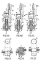
- the lower end of the anchor bolt 5 is equipped with a hole saw 65mm in diameter that will pierce the said second orifices of the hull of the wreck.
- said cylindrical rod has a throat 10c device detailed in Figure 5b.
- This throat 10c receives a open ring 10a shown in FIGS. 5a and 5c, whose diameter outside at rest ( Figure 5c) is 80 mm, so greater than the diameter of the hole, which corresponds substantially to the diameter of the hole saw which is 65 mm.
- Tool 9 continues to descend and rotate until the barrel 6 drive force on the nut 7 when it abuts on the outside of the shell as shown in Figure 4b.
- Said nut 7 has on its underside a rough surface, for example a knurling or an attached and glued washer of friction material similar to the brake pads, and on its upper side, in contact with the barrel drive, an insert ring 7a facilitating the slip, for example a bronze ring. So during the whole phase initial drilling, the thrust of the drill 9 is transmitted to the bolt anchoring 5 through said nut 7, the torque being transmitted by the key 5a; said nut rotates at the same time as the anchor bolt: it remains fixed in relation to the anchor bolt.
- Anchor bolt continues its rotation although the drill 9 exerts a strong push on said nut, which is made possible by the bronze ring 7a.
- the left-hand threading has the effect of tightening the bolt 5 which then goes back inside the training barrel 6 until the ring 10a, naturally expanded position abuts on the face internal hull.
- the hydraulic motor 86 reaches its torque maximum, it hangs and the tightening is complete.
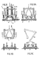
- FIG. 6a shows in sectional view the base 2 fixed to the hull of the wreck by four anchor bolts 5.
- the hole saw main 14 pierced the large diameter orifice 26 through the shell and the bell saw 14 is being wound up inside the main body 17.
- the base 2 comprises a closure means 15 or valve integrated guillotine type insulation, horizontal translation, operable from the outside.
- Said guillotine is maneuvered horizontally by an external actuator 15a, secured to a cooperating threaded rod 15b with an integral nut 15c of said guillotine, as shown in FIG.
- the actuator 15a may be a hydraulic motor or electric, but advantageously uses a hydraulic tool ROV 50 to actuate the opening or closing of the valve 15 as represented in FIG. 6b.
- the guillotine valve 15 is shown completely open in FIGS. 2 and 6a, while it is shown being closed on the plan view of Figures 3 and 6b and completely closed in FIG. 6c.
- Said seal has a thickness such that after compression when anchoring the base to the wall, its thickness corresponds to that said shims.
- the seal 20 shown as having the same thickness that the wedges 21 can, in fact, at rest have a thickness double or triple.
- the longitudinal sliding of said second cutting means 14 is provided by a ram 16 with rod out of said main body 17 allowing a visual control of the positioning of said second cutting means 14 by relative to said wall 1b, in particular during the cutting of the wall, said control being performed by the ROV camera.
- Said second cutting means 14 is able to cooperate with a means retaining 22 of the wall washer 1c 1b cut after cutting it. This advantageously makes it possible to prevent the washer from remaining at the surface of a thick fluid that one would like to evacuate through said large orifice of the wall by obstructing it, as shown in FIGS. 7a, 7b and 7c.
- Said second retaining means 22 comprises a third means of circular section 23 adapted to cooperate with said second cutting means 14 and pierce a third hole of smaller diameter than said second large central orifice 26 in the wall portion intended to be cut by said second cutting means 14, before said second cutting means 14 did not cut the large hole.
- Said second means of retainer 22 of the washer is a second means of automatic blocking constituted by the combination of a second open annular segment elastic band 24 inserted in force and held in a peripheral groove, by a third ring 25 covering it, at the lower end of a rod cylindrical support supporting said third cutting means.
- the diameter of said third ring 25 is greater than that of said third small orifice of the wall so that after cutting said third orifice and after crossing the wall by said cylindrical rod supporting said third cutting means, said second segment 24 is released in radial extension partially out of his throat while remaining there, which allows to retain and reassemble said washer when said second cutting means 14 is retracted inside said main body 17.
- Figures 7a, 7b and 7c illustrate a preferred version of a second medium type cutting hole saw 14 to which is secured a second cylindrical drive barrel 14 1 having a cylindrical hole 2 to 14 in which is installed a said second cylindrical retaining means 22 provided with a drive key 22a, and retained by a shear pin 22b.
- the lower part of said second cylindrical retaining means 22 is equipped with a third circular sawing device of the bell-saw type 23, of 65 mm, of an open ring 24 located in a groove of said second cylindrical retaining means 22, and a second sliding ring 25, as described above with reference to Figures 4a, 4b and 4c.
- the ring 24 resumes its diameter natural 80 mm after crossing the wall.
- the main bell saw 14 then attack the wall 1b and cross it completely.
- the washer 1c remains captive of the retaining ring 24.
- the washer 1c is thus recovered.
- Said shuttle reservoir 30 comprises a main envelope flexible or rigid 30a with cylindrical peripheral wall surmounted by a dome rigid 30b having a shell-shaped profile in vertical section, said dome preferably enclosing buoyancy elements 30c such as the syntactic foam to control its rise to the surface under the simple action of Archimedes' thrust, by shifting preferably the buoyancy center of said shuttle tank filled with fluid upwards relative to its apparent center of gravity in the water.
- buoyancy elements 30c such as the syntactic foam to control its rise to the surface under the simple action of Archimedes' thrust, by shifting preferably the buoyancy center of said shuttle tank filled with fluid upwards relative to its apparent center of gravity in the water.
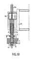
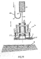
- FIG. 11 shows the descent of a device 1a comprising a buoyancy element 42 to which the device is suspended by a cable 44, which makes it possible to control the speed of descent of the device 1a and the raising of the upper structure 4.
- Said blocks 41 of said cable or large heavy links of said chain link, in said lower portion of said second cable or chain have a shape such as when bending said cable or said chain, two adjacent blocks or two adjacent heavy links come into abutment against each other thus limiting the local radius of curvature of said cable or said chain.
- FIGS. 9a, 9b and 9c a variant of FIG. embodiment in which said base 2 is anchored to receive lifting means 60.
- FIG. 10 an embodiment variant is shown anchor bolts with respect to the embodiment of FIGS. 4a, 4b and 4c in which the cylinders 8a, 8b engines and training guns 6 are fixed relative to the frame 4, and the longitudinal sliding of Anchor bolts are made by relative longitudinal sliding of the bolt anchoring relative to the rotational drive barrel 6.
- the shuttle reservoir 30 is kept close to the base 2 to by means of anchoring means comprising at least one anchoring cable crow's foot connected to a first attachment point 54 fixed on the lower part said tank and at least one second anchor point 55 on said base 2.
- said shuttle tank when said shuttle tank is full, it realizes a step of automatic disconnection of said anchoring means which is preferably performs automatically when the shuttle tank has reached a predetermined filling rate, especially when the reservoir is full or almost full.
- At least one said anchoring cable 54 cooperates with a first automatic disconnection device on which is exerted a traction corresponding to the buoyancy of Archimedes exerted on the said shuttle tank and its cargo, traction transmitted by said cable anchoring device, said disconnecting device having the effect of causing disconnection of said anchor cable by de-securing said cable anchoring54 with said base 2 or by breaking said anchor cable, and to authorize the at least partial ascent of said shuttle tank when this traction reaches a first determined threshold value, preferably when said shuttle tank is filled with effluents.
- the surface operator is thus warned, via a embedded camera in the ROV, from the end of the filling, and the ROV can to release the cable 54, which makes it possible to raise the tank towards the surface by perfectly controlling the ascent thanks to the chain system 40-41.
- the anchoring of the base to the wall has been described using four bolts forming a rectangle, but we will advantageously consider additional bolts to ensure a perfectly anchored reliable, in case the drilling and tightening of one or more bolts fail.
- restraining means have been described as being composed of a elastic segment 10a in the picked up position, held by a ring 10b, but we remain in the spirit of the invention by considering cleats, cylinders or balls which can move radially in orifices or grooves and urged outwards by springs, said cleats, cylinders or balls being held in position picked up by the ring slider 10b and released by the force of said springs for create the stop on the inner face of the wall when removing the bolt to outside said wall.
Abstract
Description
- un premier module comprenant des moyens d'extraction d'un matériau fluide destiné à être extrait à travers l'ouverture d'un conteneur tels que des moyens de pompage, et
- un deuxième module destiné à être ancré sur la paroi dudit conteneur comprenant des moyens de fermeture de l'ouverture du conteneur,
- ledit premier module comprenant également des moyens de perçage de la paroi et fixation dudit second module sur la paroi et des moyens de formation d'une grande ouverture sur la paroi du conteneur,
- lesdits premier et second modules pouvant être connectés l'un à l'autre puis déconnectés.
- une structure support supérieure dessous laquelle ladite embase est solidarisée, ladite embase comprenant des premiers orifices cylindriques ,
- ladite supérieure structure supportant des boulons d'ancrage aptes à être entraínés en coulissement et en rotation à travers lesdits premiers orifices de l'embase,
- lesdits boulons comprenant à leurs extrémités :
- des premiers moyens de coupe aptes à percer des seconds orifices circulaires dans ladite paroi, et
- des premiers moyens de blocage automatique de l'embase aptes à ancrer la dite embase sur la dite paroi après percement;
- lesdits premiers moyens de blocage automatique comprenant des écrous et des premiers moyens de retenue automatique de la paroi,
- chaque dit boulon comprenant une zone filetée apte à coopérer avec chaque dit écrou dans lequel il est engagé, de sorte que, lorsque ledit écrou vient buter sur ladite embase autour desdits premiers orifices, ledit écrou est apte à se bloquer fixement contre ladite embase, et le vissage dudit boulon dans ledit écrou provoque alors l'ancrage de ladite embase sur la paroi par serrage de celle-ci entre ledit écrou fixe et lesdits premiers moyens de retenue automatique, ces derniers étant aptes à venir en appui contre la face interne de la paroi après avoir traversé lesdits seconds orifices.
- une structure support supérieure dessous laquelle ladite embase est solidarisée de manière réversible par l'intermédiaire de moyens de liaison réversible,
- ladite structure supportant des boulons d'ancrage constitués de tiges cylindriques filetées, d'axe s'étendant dans une direction longitudinale ZZ', aptes à être entraínés d'une part en coulissement dans ladite direction longitudinale ZZ' à l'aide de vérins et d'autre part en rotation autour de leurs dits axes longitudinaux à l'aide de moteurs, lesdits vérins et moteurs étant supportés par ladite structure supérieure,
- lesdits boulons comprenant à leurs extrémités :
- des premiers moyens de coupe, de préférence tels que trépan ou scie-cloche, aptes à percer des seconds orifices circulaires dans ladite paroi lorsque lesdits boulons sont appliqués en pression contre la paroi et en rotation axiale selon leur axe longitudinale ZZ',
- et des premiers moyens de blocage automatique de l'embase aptes à ancrer la dite embase sur la dite paroi après percement;
- ladite embase étant apte à être posée sur ladite paroi et comprenant des premiers orifices cylindriques d'axes ZZ' aptes à être traversés par lesdits boulons (c'est-à-dire lorsque lesdits boulons coulissent longitudinalement) et dans lesquels, de préférence, les extrémités libres desdits boulons comprenant desdits premiers moyens de coupe et, de préférence, desdits premiers moyens de blocage, sont aptes à être logées en position initiale avant ancrage,
- lesdits premiers moyens de blocage automatique de l'embase comprenant des écrous et des premiers moyens de retenue automatique de la paroi, chaque dit boulon comprenant une zone filetée apte à coopérer avec un dit écrou dans lequel il est engagé, le sens du filetage étant tel que, lorsque ledit boulon est actionné en rotation et coulisse dans ladite direction longitudinale ZZ' vers ladite paroi, de manière à ce que ledit boulon traverse un dit premier orifice de l'embase et perce un dit second orifice de ladite paroi, lesdits rotation et coulissement se font sans déplacement relatif dudit boulon par rapport audit écrou, puis lorsque ledit écrou vient buter sur ladite embase (c'est-à-dire par coulissement en direction de ladite paroi), ledit écrou est apte à se bloquer fixement contre ladite embase, ledit écrou comportant de préférence une sous-face rugueuse, et le sens dudit filetage permet que la rotation dudit boulon provoque alors un coulissement longitudinal en sens inverse dudit boulon (c'est à dire en s'éloignant de ladite paroi) avec déplacement relatif dudit boulon par rapport audit écrou fixe dans la zone filetée, et provoque ensuite l'ancrage de ladite embase sur la paroi par serrage de celle-ci entre ledit écrou fixe et lesdits premiers moyens de retenue automatique, ces derniers étant aptes à venir en appui contre la face interne de la paroi, de préférence en périphérie desdits seconds orifices, après avoir traversé lesdits seconds orifices.
- ladite structure supérieure supporte des canons d'entraínement desdits boulons et des moteurs aptes à actionner lesdits canons en rotation autour de leurs axes ZZ', lesdits canons comprenant des logements creux cylindriques d'axe dans la direction longitudinale ZZ' dans lesquels sont logés les parties supérieures desdits boulons d'ancrage, et
- lesdits canons, lorsqu'ils sont en rotation, sont aptes à entraíner en rotation lesdits boulons grâce à des éléments de guidage complémentaires situés respectivement dans lesdits logements creux et sur lesdites parties supérieures des boulons, de préférence des éléments mâles tels que des clavettes longitudinales rapportées à la surface des boulons et des éléments femelles complémentaires tels que des rainures ou gorges correspondantes dans ledit canon, et
- chaque dit boulon comprend une zone filetée apte à coopérer avec un dit écrou situé en dessous desdits éléments de guidage rapportés. On comprend que lesdits éléments de guidage à la surface du boulon sont rapportés à la surface du boulon après que le boulon ait été vissé dans l'écrou. D'autre part, on comprend que lesdits éléments de guidage autorisent le coulissement longitudinal relatif desdits boulons par rapport aux dits canons.Lesdits canons peuvent être montés fixes sur la structure supérieure, lesdits boulons étant entraínés en coulissement directement par des vérins à l'intérieur desdits canons.Dans un mode de réalisation avantageux, les canons sont montés coulissant sur un bâti, et le dispositif selon l'invention est caractérisé en ce que
- ladite structure support supérieure comporte un bâti de guidage sur lequel peuvent coulisser dans une direction longitudinale ZZ', sous l'action de dits vérins montés fixes sur ledit bâti, des chariots supportant desdits moteurs aptes à actionner desdits canons d'entraínement en rotation autour de leurs axes dans la dite direction longitudinale ZZ', et
- lesdits boulons comprennent une zone filetée située en dessous de leurs dits éléments de guidage, et coopèrent avec des écrous dans lesquels ils sont engagés au niveau de ladite zone filetée, de sorte que l'extrémité inférieure desdits canons est en contact glissant avec la face supérieure desdits écrous, de préférence par l'intermédiaire d'une bague en bronze et lesdits boulons d'ancrage sont aptes à coulisser longitudinalement à frottement dur à l'intérieur desdits canons de sorte qu'ils restent en place et ne s'échappent pas vers le bas de leur propre poids.
- la dite structure supérieure supporte un second moyen de coupe circulaire, de préférence du type trépan ou scie-cloche, apte à découper un second grand orifice central d'axe longitudinal ZZ' dans la paroi, notamment de plus grand diamètre que lesdits seconds orifices, et des moyens de type vérins et moteurs aptes à faire coulisser dans ladite direction longitudinale ZZ' et à actionner en rotation d'axe dans ladite direction longitudinale ZZ', ledit second moyen de coupe, et
- ledit premier grand orifice central de l'embase étant positionné en coïncidence avec ledit second moyen de coupe circulaire et étant apte à être traversé par ledit second moyen de coupe lorsque celui-ci est en coulissement longitudinal vers ladite paroi, et apte à être obturé par un moyen de fermeture, de préférence du type guillotine à translation horizontale. Ledit moyen de fermeture peut être actionnable de l'extérieur, de préférence par un robot commandé à distance du type ROV ou actionnable automatiquement.
- la figure 1 est une coupe en vue de côté de la cuve ou d'une épave sur laquelle est installé un réservoir navette relié à une embase selon l'invention, en cours de remplissage,
- la figure 2 est une vue en coupe de l'embase d'un dispositif de piquage selon l'invention en phase d'approche lors de sa descente vers l'épave, selon BB-B'B' de la figure 3.
- la figure 3 est une vue en plan partielle d'une embase selon l'invention associée à une coupe selon AA-A'A' de la figure 2,
- les figures 4a, 4b et 4c sont des coupes en vue de côté d'une partie d'une structure supérieure montrant un boulon d'ancrage muni d'un outil de forage et de moyens de blocage en vue de l'ancrage d'une embase sur la coque de l'épave, représenté en cours de forage (figure 4a), puis en cours de serrage des moyens de blocage (figure 4b), et enfin, en fin de blocage (figure 4c),
- les figures 5a, 5b et 5c sont des vues de côté des moyens de coupe et moyens de blocage de la figure 4, détaillant la forme d'un segment de blocage à l'état contraint en cours de forage (figures 5a et 5b gauche), puis déployé après forage (figure 5b droite ― figure 5c),
- les figures 6a, 6b et 6c représentent une coupe en vue de côté d'un dispositif selon l'invention, comprenant une structure supérieure de piquage munie de moyens d'ancrage d'une embase sur la coque d'une épave ou une paroi de cuve au fond de la mer, après ancrage de ladite embase et après percement d'un orifice principal d'évacuation dans ladite paroi, le moyen de coupe du type scie-cloche étant partiellement rétracté dans le corps principal de la structure supérieure (figure 6a), puis la scie-cloche étant complètement rétractée, et le moyen de fermeture de type guillotine de l'orifice principal de l'embase étant en cours de fermeture (figure 6b), et, après fermeture complète de la vanne à guillotine de l'embase (figure 6c), la structure supérieure est déconnectée de l'embase,
- les figures 7a, 7b et 7c représentent en coupe une vue de côté du moyen de coupe principal du type scie-cloche de la structure supérieure, équipé d'un dispositif de retenue de la rondelle après perforation de la coque de la paroi,
- la figure 7d représente une coupe en vue de côté d'une partie dudit moyen de coupe et dudit moyen de retenue séparé dudit moyen de coupe après rupture d'une goupille de cisaillement,
- la figure 8 représente un dispositif d'ancrage d'une embase et perçage d'une paroi selon l'invention montrant les moyens de liaison réversibles entre ladite embase et la structure supérieure supportant les moyens d'ancrage et de perçage,
- les figures 9a, 9b et 9c montrent un dispositif de pose et d'installation d'une embase par ancrage sur une paroi, en cours de pose (figure 9a), après ancrage (figure 9b) et avec installation d'un moyen de levage sur ladite embase (figure 9c),
- la figure 10 représente une variante de réalisation d'un moyen d'ancrage des figures 4a, 4b et 4c dans lequel les moyens d'actionnement en rotation 8 desdits boulons d'ancrage sont fixes et lesdits boulons d'ancrages sont actionnés en coulissement longitudinal relatif par rapport aux dits moyens d'actionnement en rotation.
- La figure 11 représente la descente d'un dispositif d'ancrage et perçage selon l'invention contrôlée par une chaíne de stabilisation et des éléments de flottabilité.
- une embase 2 et
- une structure support supérieure 4.
- des premiers moyens de coupe circulaire 9 consistant en des trépans ou scies-cloches aptes à former desdits seconds orifices 12 dans ladite paroi de forme circulaire de diamètre d'au moins 30, plus particulièrement de 30 à 125 mm, plus particulièrement encore de 35 à 75 mm, lorsque lesdits boulons sont appliqués en pression contre la paroi par coulissement longitudinal vers le bas et en rotation axiale simultanée selon leur axe longitudinal ZZ', et
- desdits premiers moyens de blocage automatiques 7, 10a, 10 b, aptes à ancrer ladite embase 2 sur ladite paroi 1b après percement.
Claims (18)
- Dispositif d'installation et d'ancrage (1a) d'une embase (2) destinée à être ancrée sur une paroi (1b) au fond de la mer, caractérisé en ce qu'il comprend :une structure support supérieure (4) dessous laquelle ladite embase (2) est solidarisée, ladite embase comprenant des premiers orifices cylindriques (11),ladite supérieure structure (4) supportant des boulons d'ancrage (5) aptes à être entraínés en coulissement et en rotation à travers lesdits premiers orifices (11) de l'embase (2),lesdits boulons comprenant à leurs extrémités :des premiers moyens de coupe (9) aptes à percer des seconds orifices circulaires (12) dans ladite paroi (1b), etdes premiers moyens de blocage automatique de l'embase (7, 10a, 10b, 10c) aptes à ancrer la dite embase sur la dite paroi (1b) après percement;lesdits premiers moyens de blocage automatique de l'embase comprenant des écrous (7) et des premiers moyens de retenue automatique de la paroi (10a, 10b, 10c),chaque dit boulon comprenant une zone filetée apte à coopérer avec chaque dit écrou (7) dans lequel il est engagé, de sorte que, lorsque ledit écrou (7) vient buter sur ladite embase autour desdits premiers orifices (11), ledit écrou est apte à se bloquer fixement contre ladite embase, et le vissage dudit boulon dans ledit écrou provoque alors l'ancrage de ladite embase sur la paroi par serrage de celle-ci entre ledit écrou fixe (7) et lesdits premiers moyens de retenue automatique (10a, 10b, 10c), ces derniers étant aptes à venir en appui contre la face interne de la paroi (1b) après avoir traversé lesdits seconds orifices (12).
- Dispositif d'installation et d'ancrage (1a) d'une embase (2) destinée à être ancrée sur une paroi (1b) au fond de la mer selon la revendication 1, caractérisé en ce qu'il comprend :une structure support supérieure (4) dessous laquelle ladite embase (2) est solidarisée de manière réversible par l'intermédiaire de moyens de liaison réversible (3),ladite structure (4) supportant des boulons d'ancrage (5) constitués de tiges cylindriques filetées, d'axes s'étendant dans une direction longitudinale ZZ', aptes à être entraínés d'une part en coulissement dans ladite direction longitudinale ZZ' à l'aide de vérins (8a) et d'autre part en rotation autour de leurs dits axes longitudinaux à l'aide de moteurs (8b), lesdits vérins et moteurs étant supportés par ladite structure supérieure,lesdits boulons comprenant à leurs extrémités :des premiers moyens de coupe (9), de préférence tels que trépan ou scie-cloche, aptes à percer des seconds orifices circulaires (12) dans ladite paroi lorsque lesdits boulons sont appliqués en pression contre la paroi et en rotation axiale selon leur axe longitudinale ZZ',et desdits premiers moyens de blocage automatique de l'embase (7, 10a, 10b, 10c) aptes à ancrer la dite embase sur la dite paroi (1b) après percement;ladite embase étant apte à être posée sur ladite paroi et comprenant des premiers orifices cylindriques (11) d'axes ZZ' aptes à être traversés par lesdits boulons et dans lesquels, de préférence, les extrémités libres desdits boulons comprenant desdits premiers moyens de coupe (9) et, de préférence, desdits premiers moyens de blocage (7, 10a, 10b, 10c), sont aptes à être logées en position initiale avant ancrage,lesdits premiers moyens de blocage automatique comprenant des écrous (7) et desdits premiers moyens de retenue automatique de la paroi (10a, 10b, 10c), chaque dit boulon comprenant une zone filetée apte à coopérer avec un dit écrou (7) dans lequel il est engagé, le sens du filetage étant tel que, lorsque ledit boulon est actionné en rotation et coulisse dans ladite direction longitudinale ZZ' vers ladite paroi de manière à ce que ledit boulon traverse un dit premier orifice (11) de l'embase et perce un dit second orifice (12) de ladite paroi, lesdits rotation et coulissement se font sans déplacement relatif dudit boulon (5) par rapport audit écrou (7), puis lorsque ledit écrou (7) vient buter sur ladite embase, ledit écrou est apte à se bloquer fixement contre ladite embase, ledit écrou comportant de préférence une sous-face rugueuse, et le sens dudit filetage permet que la rotation dudit boulon provoque alors un coulissement longitudinal en sens inverse dudit boulon avec déplacement relatif dudit boulon par rapport audit écrou (7) fixe dans la zone filetée, et provoque ensuite l'ancrage de ladite embase sur la paroi par serrage de celle-ci entre ledit écrou fixe (7) et lesdits premiers moyens de retenue automatique (10a, 10b, 10c), ces derniers étant aptes à venir en appui contre la face interne de la paroi (1b), de préférence en périphérie desdits seconds orifices (12), après avoir traversé lesdits seconds orifices.
- Dispositif selon la revendication 2, caractérisé en ce queladite structure supérieure (4) supporte des canons (6) d'entraínement desdits boulons et des moteurs (8b) aptes à actionner lesdits canons en rotation autour de leurs axes ZZ', lesdits canons comprenant des logements creux cylindriques d'axes dans la direction longitudinale ZZ' dans lesquels sont logés les parties supérieures desdits boulons d'ancrage (5), etlesdits canons (6), lorsqu'ils sont en rotation, sont aptes à entraíner en rotation lesdits boulons grâce à des éléments de guidage complémentaires (5a) situés respectivement dans lesdits logements creux et sur lesdites parties supérieures des boulons, de préférence des éléments mâles tels que des clavettes longitudinales (5a) rapportés à la surface des boulons et des éléments femelles complémentaires tels que des rainures ou gorges correspondantes dans ledit canon, etchaque dit boulon (5) comprend une zone filetée apte à coopérer avec un dit écrou (7) situé en dessous desdits éléments de guidage rapportés (5a).
- Dispositif selon la revendication 3, caractérisé en ce queladite structure support supérieure (4) comporte un bâti de guidage (4a) sur lequel peuvent coulisser dans une direction longitudinale ZZ', sous l'action de dits vérins (8a) montés fixes sur ledit bâti, des chariots (4b) supportant desdits moteurs (8b) aptes à actionner desdits canons d'entraínement (6) en rotation autour de leurs axes dans la dite direction longitudinale ZZ', etlesdits boulons (5) comprennent une zone filetée située en dessous de leurs dits éléments de guidage (5a), et coopèrent avec des écrous (7) dans lesquels ils sont engagés au niveau de ladite zone filetée, de sorte que l'extrémité inférieure desdits canons (6) est en contact glissant avec la face supérieure desdits écrous (7), de préférence par l'intermédiaire d'une bague en bronze (7a), et lesdits boulons d'ancrage (5) sont aptes à coulisser longitudinalement à frottement dur à l'intérieur desdits canons (6) de sorte qu'ils restent en place et ne s'échappent pas vers le bas de leur propre poids.
- Dispositif selon l'une des revendications 1 à 4, caractérisé en ce que lesdits premiers moyens de retenue automatique (10a, 10b, 10c) comprennent des premiers éléments de retenue (10a, 10b) aptes à être contraints ou escamotés à l'aide de seconds éléments de retenue (10c) pour permettre leur passage à travers lesdits premier (11) et second (11) orifices, et lesdits premier éléments de retenue automatique sont aptes à être libérés en position d'extension ou déployés automatiquement après passage à travers lesdits seconds orifices (12) dans ladite paroi, de manière à assurer une retenue de la paroi et son ancrage par serrage entre lesdits écrous (7) et lesdits premiers éléments de retenue (10a) lorsque les boulons (5) sont actionnés en rotation et coulissement en sens inverse depuis l'intérieur vers l'extérieur de ladite paroi.
- Dispositif selon l'une des revendications 5, caractérisé en ce que lesdits premiers moyens de retenue automatique sont constitués par des segments (10a) en forme d'anneaux ouverts aptes à être insérés en force de par leur élasticité dans des gorges (10c) à l'extrémité inférieure desdits boulons (5) au dessus desdits premiers moyens de coupe (9), lesdits segments (10a) étant maintenus dans lesdites gorges (10c) par des bagues périphériques (10b) appliquées contre la surface externe des boulons au niveau desdits segments (10a), de préférence en coulissant à jeu réduit, de telle sorte que lesdites bagues périphériques, de par leur diamètre plus important que celui desdits seconds orifices, sont retenues par la face supérieure de la paroi (1b) après perçage desdits seconds orifices, et sont aptes à libérer ainsi lesdits segments (10a) en extension radiale élastique partiellement hors desdits gorges (10c) dans lesquelles ils restent bloqués après passage par coulissement longitudinale à travers lesdits seconds orifices (12) de la paroi, lesdits segments (10a) en extension radiale partielle empêchant leur passage en sens inverse à travers la paroi et permettant ainsi le serrage de la paroi par les boulons entre ledit écrou et ledit segment (10a) en extension par coulissement en sens inverse desdits boulons résultant de leur rotation.
- Dispositif selon l'une des revendications 1 à 6, caractérisé en ce que ladite embase comprend un premier grand orifice central cylindrique (13) d'axe dans la dite direction longitudinale ZZ'.
- Dispositif selon la revendication 7, apte à réaliser, en outre, le perçage d'un second grand orifice central (26) dans ladite paroi (1b), caractérisé en ce quela dite structure supérieure (4) supporte un second moyen de coupe circulaire (14), de préférence du type trépan ou scie-cloche, apte à découper un second grand orifice central (26) d'axe dans la direction longitudinale ZZ' dans la paroi, notamment de plus grand diamètre que lesdits seconds orifices (12), et des moyens de type vérins (16) et moteurs (17) aptes à faire coulisser dans ladite direction longitudinale ZZ' et à actionner en rotation d'axe dans la direction longitudinale ZZ', ledit second moyen de coupe (14), etledit premier grand orifice central (13) de l'embase étant positionné en coïncidence avec ledit second moyen de coupe circulaire et étant apte à être traversé par ledit second moyen de coupe (14) lorsque celui-ci est en coulissement longitudinal vers ladite paroi, et ledit premier grand orifice de l'embase est apte à être obturé par un moyen de fermeture (15) de préférence du type guillotine à translation horizontale.
- Dispositif selon la revendication 8, caractérisé en ce queladite structure supérieure (4) supporte un corps principal (17) de forage fixe par rapport à ladite structure, ledit corps principal (17) comportant ledit second moyen de coupe (14) à sa base et renfermant un moteur d'actionnement (17a) en rotation et un vérin (16) de coulissement longitudinal relatif dudit second moyen de coupe (14) par rapport audit corps principal (17), etledit corps principal (17) comporte à son extrémité inférieure une bride (18) et ledit premier grand orifice central (13) de l'embase comporte une bride supérieure (19), lesdits moyens de liaison réversible (3) de ladite structure supérieure et de l'embase assurent la liaison entre lesdites brides inférieure (18) et supérieure (19).
- Dispositif selon la revendication 8 ou 9, caractérisé en ce queun joint d'étanchéité épais et déformable (20), de préférence en élastomère, est installé en sous-face de ladite embase (2) à la périphérie dudit premier grand orifice central (13) apte à assurer l'étanchéité entre ladite embase et la paroi après découpe de la paroi, etde préférence des cales (21) sont installées autour desdits premiers orifices (11) en sous-face de l'embase apte à permettre la pose stable de l'embase sur la paroi dans le cas où celle-ci serait déformée le cas échéant.
- Dispositif selon la revendication 9 ou 10, caractérisé en ce que le coulissement longitudinal dudit second moyen de coupe (14) est assuré par un vérin (16) à tige sortante dudit corps principal (17) permettant un contrôle visuel du positionnement dudit second moyen de coupe (14) par rapport à ladite paroi (1b), notamment pendant la découpe de la paroi.
- Dispositif selon l'une des revendications 8 à 11, caractérisé en ce que ledit second moyen de coupe (14) est apte à coopérer avec un second moyen de retenue (22) de la rondelle (1c) de paroi (1b) découpée après découpe dudit second grand orifice central de la paroi.
- Dispositif selon la revendication 12, caractérisé en ce que ledit second moyen de retenue (22) comprend un troisième moyen de coupe circulaire (23) apte à coopérer avec ledit second moyen de coupe (14) de manière à percer un troisième orifice de plus petit diamètre que ledit second grand orifice central (26) dans la partie (1c) de paroi en forme de rondelle destinée à être découpée par ledit second moyen de découpe (14), avant que ledit second moyen de coupe (14) n'ait effectué la découpe dudit grand orifice, et ledit second moyen de retenue (22) de ladite rondelle est un second moyen de blocage automatique constitué par la combinaison d'un second segment annulaire ouvert élastique (24) inséré en force et maintenu dans une gorge périphérique par une troisième bague (25) le recouvrant, à l'extrémité inférieure d'une tige cylindrique supportant ledit troisième moyen de coupe, le diamètre de ladite troisième bague (25) étant supérieure à celui dudit troisième petit orifice de la paroi de sorte que, après découpe dudit troisième orifice et après traversée de la paroi par ladite tige cylindrique supportant ledit troisième moyen de coupe, ledit second segment (24) est libéré en extension radiale élastique partiellement hors de sa gorge tout en y restant maintenu, ce qui permet de retenir et de remonter ladite rondelle (1c) lorsque ledit second moyen de coupe (14) est rétracté dans la direction longitudinale ZZ'.
- Procédé de pose et d'ancrage d'une embase sur une paroi au fond de la mer sensiblement horizontale, à l'aide d'un dispositif selon l'une des revendications 1 à 13, caractérisé en ce que on réalise les étapes successives suivantes :1-on descend, depuis la surface, un dit dispositif selon l'une des revendications 1 à 13, et2-on pose ladite embase (2) sur ladite paroi (1b), et3-on actionne, en coulissement longitudinal vers la paroi et en rotation, lesdits boulons (5) et lesdits premiers moyens de coupe (9) pour percer desdits premiers orifices (11) dans ladite paroi, et4-on serre lesdits premiers moyens de blocage (10a, 10b) contre la face interne de la paroi, par dits rotation et coulissement longitudinal en sens inverse desdits boulons vers l'extérieur de la paroi, et5-le cas échéant, on désolidarise ladite structure supérieure (4) et ladite embase (2) et l'on remonte ladite structure supérieure en surface.
- Procédé selon la revendication 14, dans lequel on réalise le perçage d'une paroi au fond de la mer à l'aide d'un dispositif selon l'une des revendications 8 à 13, caractérisé en ce que l'on réalise les étapes 1 à 4 de la revendication 14, à l'aide d'un dit dispositif selon l'une des revendications 8 à 13 et on réalise les étapes ultérieures suivantes :5-on réalise la découpe dudit second grand orifice central (26) dans ladite paroi par rotation et coulissement longitudinal vers la paroi dudit second moyen de coupe (14), et6-on dégage par coulissement longitudinal en sens inverse vers l'extérieur de la paroi ledit second moyen de découpe (14), de préférence en retenant ladite rondelle (1c) de paroi découpée, et7-on obstrue ledit second orifice de l'embase à l'aide de dit moyen de fermeture (15), de préférence du type à guillotine, et8-on désolidarise ladite structure supérieure (4) par rapport à ladite embase et l'on remonte ladite structure supérieure en surface.
- Procédé de récupération d'un fluide épais tel qu'un effluent polluant, plus léger que l'eau, contenu dans une cuve d'un navire coulé et/ou endommagé reposant au fond de la mer, dans lequel :1-on réalise un procédé de pose et ancrage d'une embase et perçage de la paroi de ladite cuve à l'aide d'un dispositif selon les revendications 8 à 13, selon un procédé des revendications 14 ou 15, et2-on descend un dit réservoir navette (30) depuis la surface (40) jusqu'au dessus de ladite embase (2), et3-on ancre ledit réservoir navette sur ladite embase de manière à ce que l'ouverture inférieure (31) dudit réservoir navette coïncide avec ledit premier grand orifice central (13) de ladite embase, et4-on ouvre ledit moyen de fermeture (15) dudit premier grand orifice (13) de ladite embase et on laisse s'écouler naturellement ledit fluide contenu dans la cuve dans ledit réservoir navette par l'orifice inférieur (31) dudit réservoir navette, et5-lorsque ledit réservoir navette est rempli de fluide, on remonte ledit réservoir navette en surface après avoir refermé ledit dispositif de fermeture (15) dudit premier grand orifice de ladite embase, et6-on stocke ledit réservoir navette rempli de fluide dans un navire en surface et/ou on vide ledit réservoir navette dans ledit navire et/ou on le transporte dans un site pour y être vidé, et7.-le cas échéant, on répète les étapes 1. à 6. avec un même réservoir navette ou un autre réservoir navette jusqu'à ce que la quantité voulue soit récupérée.
- Procédé selon la revendication 16, caractérisé en ce que ledit réservoir navette (30) comprend :une enveloppe principale souple ou rigide (30a) à paroi périphérique cylindrique surmontée d'un dôme rigide (30b) présentant un profil en forme d'obus en section verticale, ledit dôme renfermant de préférence des éléments de flottabilité (30c) tels que de la mousse syntactique permettant de contrôler sa remontée en surface sous la simple action de la poussée d'Archimède, en décalant de préférence le centre de flottabilité dudit réservoir navette rempli de fluide vers le haut par rapport à son centre de gravité apparent dans l'eau.
- Procédé selon l'une des revendications 14 à 17, caractérisé en ce qu'on contrôle la vitesse de descente d'un dit dispositif (1a) de pose et ancrage de l'embase (2) ou d'un dit réservoir navette (30), le cas échéant, ou de remontée d'une dite structure supérieure (4) ou dudit réservoir navette (30), le cas échéant, avec un dispositif de stabilisation comprenant au moins un câble ou chaíne de liaison (40a, 40b) s'étendant depuis la surface, de préférence depuis un navire en surface, jusqu'à ladite structure supérieure (4) ou audit réservoir navette (30), le cas échéant, à laquelle son extrémité est reliée, ledit câble ou dite chaíne de liaison (40a, 40b) comportant une portion inférieure alourdie, de préférence par des blocs (41) disposés en chapelet le long dudit deuxième câble ou par des gros maillons plus lourds de ladite chaíne, de telle sorte que le poids de la longueur de ladite portion inférieure de dit(e) câble ou chaíne pendante dessous son point de liaison (43, 55) à ladite structure supérieure (4) ou audit réservoir navette (30), peut être réglé depuis la surface, de préférence à l'aide d'un treuil situé à bord d'un navire en surface et sur lequel l'extrémité supérieure dudit câble ou de ladite chaíne est déroulée ou enroulée, de façon à contrôler la vitesse de descente ou respectivement de remontée de ladite structure supérieure (4) ou dudit réservoir navette (30) le cas échéant.
Priority Applications (8)
| Application Number | Priority Date | Filing Date | Title |
|---|---|---|---|
| AT04358002T ATE490166T1 (de) | 2004-02-26 | 2004-02-26 | Vorrichtung und verfahren zum befestigen einer basiskonstruktion auf einer wandfläche am meeresgrund |
| DE602004030314T DE602004030314D1 (de) | 2004-02-26 | 2004-02-26 | Vorrichtung und Verfahren zum Befestigen einer Basiskonstruktion auf einer Wandfläche am Meeresgrund |
| EP04358002A EP1568600B1 (fr) | 2004-02-26 | 2004-02-26 | Dispositif et procédé d'ancrage d'une embase sur une paroi au fond de la mer |
| DE602004004382T DE602004004382D1 (de) | 2003-03-26 | 2004-03-25 | Vorrichtung und verfahren für die stabilisierung und kontrolle der niedergang und des aufstiegs einer schweren struktur zwischen meeresoberfläche und meeresboden |
| ES04742350T ES2280032T3 (es) | 2003-03-26 | 2004-03-25 | Dispositivo y procedimiento de estabilizacion y de control del descenso o elevacion de una estructura pesada entre la superficie y el fondo del mar. |
| US10/550,263 US20070089656A1 (en) | 2003-03-26 | 2004-03-25 | Device and a method for stabilizing and controlling the lowering or raising of a structure between the surface and the bed of the sea |
| EP04742350A EP1606160B1 (fr) | 2003-03-26 | 2004-03-25 | Dispositif et procede de stabilisation et de controle de la descente ou remontee d'une structure lourde entre la surface et le fond de la mer |
| PCT/FR2004/000742 WO2004087495A2 (fr) | 2003-03-26 | 2004-03-25 | Dispositif et procede de stabilisation et de controle de la descente ou remontee d’une structure lourde entre la surface et le fond de la mer |
Applications Claiming Priority (1)
| Application Number | Priority Date | Filing Date | Title |
|---|---|---|---|
| EP04358002A EP1568600B1 (fr) | 2004-02-26 | 2004-02-26 | Dispositif et procédé d'ancrage d'une embase sur une paroi au fond de la mer |
Publications (2)
| Publication Number | Publication Date |
|---|---|
| EP1568600A1 true EP1568600A1 (fr) | 2005-08-31 |
| EP1568600B1 EP1568600B1 (fr) | 2010-12-01 |
Family
ID=34746181
Family Applications (1)
| Application Number | Title | Priority Date | Filing Date |
|---|---|---|---|
| EP04358002A Expired - Lifetime EP1568600B1 (fr) | 2003-03-26 | 2004-02-26 | Dispositif et procédé d'ancrage d'une embase sur une paroi au fond de la mer |
Country Status (3)
| Country | Link |
|---|---|
| EP (1) | EP1568600B1 (fr) |
| AT (1) | ATE490166T1 (fr) |
| DE (1) | DE602004030314D1 (fr) |
Cited By (8)
| Publication number | Priority date | Publication date | Assignee | Title |
|---|---|---|---|---|
| FR2913228A1 (fr) * | 2007-03-02 | 2008-09-05 | Saipem S A Sa | Dispositif de decoupe et ouverture/fermeture d'un orifice dans une paroi au fond de la mer |
| WO2008107497A1 (fr) * | 2007-03-08 | 2008-09-12 | Sebastian Bendito Vallori | Système hydrodynamique d'extraction subaquatique et transport sûrs apte pour un quelconque liquide moins dense que l'eau ou vaisseau ayant coulé à acquisition énergétique gratuite depuis le milieu enveloppant |
| WO2008090363A3 (fr) * | 2007-01-27 | 2008-10-09 | Deep Tek Ltd | Procédé et appareil pour fixer un conduit à une structure |
| US7882794B2 (en) | 2003-03-26 | 2011-02-08 | Saipem S.A. | Buoyancy device and method for stabilizing and controlling lowering or raising of a structure between the surface and the sea floor |
| WO2014187759A1 (fr) * | 2013-05-20 | 2014-11-27 | Alfons Håkans Oy Ab | Appareil et procédé de récupération de liquide à partir d'un récipient immergé |
| CN108248777A (zh) * | 2018-02-27 | 2018-07-06 | 天津大学 | 一种深海多功能长期原位观测系统 |
| WO2020188291A3 (fr) * | 2019-03-19 | 2020-10-29 | Ardent Maritime UK Limited | Récupération ou transfert de fluide à distance |
| WO2020242076A1 (fr) * | 2019-05-28 | 2020-12-03 | 주식회사 코리아오션텍 | Appareil pour décharger de l'huile résiduelle d'un navire en train de couler ayant été perforé |
Families Citing this family (1)
| Publication number | Priority date | Publication date | Assignee | Title |
|---|---|---|---|---|
| CN102490878B (zh) * | 2011-11-25 | 2014-03-12 | 北京航空航天大学 | 单自由度对称式摆动驱动的大展缩比水下机器人回收装置 |
Citations (4)
| Publication number | Priority date | Publication date | Assignee | Title |
|---|---|---|---|---|
| GB137744A (en) * | 1919-06-04 | 1920-01-22 | Walter Church Beckwith | Improvements in boring and fastening devices |
| US3831387A (en) | 1972-03-24 | 1974-08-27 | Salvage Oil Syst Ltd | Apparatus for salvaging oil from sunken vessels |
| EP0730543A1 (fr) | 1993-11-30 | 1996-09-11 | Framo Dev Ltd | Appareil d'extraction d'un materiau fluide d'un conteneur |
| FR2804935A1 (fr) | 2000-02-11 | 2001-08-17 | Bouygues Offshore | Procede et installation de recuperation d'effluents en mer |
-
2004
- 2004-02-26 AT AT04358002T patent/ATE490166T1/de not_active IP Right Cessation
- 2004-02-26 EP EP04358002A patent/EP1568600B1/fr not_active Expired - Lifetime
- 2004-02-26 DE DE602004030314T patent/DE602004030314D1/de not_active Expired - Lifetime
Patent Citations (5)
| Publication number | Priority date | Publication date | Assignee | Title |
|---|---|---|---|---|
| GB137744A (en) * | 1919-06-04 | 1920-01-22 | Walter Church Beckwith | Improvements in boring and fastening devices |
| US3831387A (en) | 1972-03-24 | 1974-08-27 | Salvage Oil Syst Ltd | Apparatus for salvaging oil from sunken vessels |
| US5775390A (en) * | 1993-11-03 | 1998-07-07 | Mohn; Frank | Apparatus for extraction of a fluent material from a container |
| EP0730543A1 (fr) | 1993-11-30 | 1996-09-11 | Framo Dev Ltd | Appareil d'extraction d'un materiau fluide d'un conteneur |
| FR2804935A1 (fr) | 2000-02-11 | 2001-08-17 | Bouygues Offshore | Procede et installation de recuperation d'effluents en mer |
Cited By (16)
| Publication number | Priority date | Publication date | Assignee | Title |
|---|---|---|---|---|
| US7882794B2 (en) | 2003-03-26 | 2011-02-08 | Saipem S.A. | Buoyancy device and method for stabilizing and controlling lowering or raising of a structure between the surface and the sea floor |
| US8776706B2 (en) | 2003-03-26 | 2014-07-15 | Salpem S.A. | Buoyancy device and a method for stabilizing and controlling the lowering or raising of a structure between the surface and the bed of the sea |
| US8528186B2 (en) | 2007-01-27 | 2013-09-10 | Deep Tek Ip Limited | Method and apparatus for securing a conduit to a structure |
| AU2008208681B2 (en) * | 2007-01-27 | 2013-10-10 | Deep Tek Underwater Ip Limited | Method and apparatus for securing a conduit to a structure |
| WO2008090363A3 (fr) * | 2007-01-27 | 2008-10-09 | Deep Tek Ltd | Procédé et appareil pour fixer un conduit à une structure |
| JP2010516971A (ja) * | 2007-01-27 | 2010-05-20 | ディープ テック アンダーウォーター アイピー リミテッド | 構造物に導管を固定する方法及び装置 |
| WO2008116997A1 (fr) | 2007-03-02 | 2008-10-02 | Saipem S.A. | Dispositif de decoupe et ouverture/fermeture d'un orifice dans une paroi au fond de la mer |
| US8186294B2 (en) | 2007-03-02 | 2012-05-29 | Saipem S.A. | Device for cutting out and opening/closing an orifice in a wall at the bottom of the sea |
| FR2913228A1 (fr) * | 2007-03-02 | 2008-09-05 | Saipem S A Sa | Dispositif de decoupe et ouverture/fermeture d'un orifice dans une paroi au fond de la mer |
| ES2304215A1 (es) * | 2007-03-08 | 2008-09-16 | Sebastian Enriq Bendito Vallori | Sistema hidrodinamico de extraccion subacuatica y transporte seguros aptos para cualquier liquido menos denso que el agua o buque fundido co adquisicion energetica gratuita desde el medio envolvente. |
| WO2008107497A1 (fr) * | 2007-03-08 | 2008-09-12 | Sebastian Bendito Vallori | Système hydrodynamique d'extraction subaquatique et transport sûrs apte pour un quelconque liquide moins dense que l'eau ou vaisseau ayant coulé à acquisition énergétique gratuite depuis le milieu enveloppant |
| WO2014187759A1 (fr) * | 2013-05-20 | 2014-11-27 | Alfons Håkans Oy Ab | Appareil et procédé de récupération de liquide à partir d'un récipient immergé |
| CN105324301A (zh) * | 2013-05-20 | 2016-02-10 | 阿尔方斯哈坎斯有限公司 | 用于从水下容器回收液体的设备和方法 |
| CN108248777A (zh) * | 2018-02-27 | 2018-07-06 | 天津大学 | 一种深海多功能长期原位观测系统 |
| WO2020188291A3 (fr) * | 2019-03-19 | 2020-10-29 | Ardent Maritime UK Limited | Récupération ou transfert de fluide à distance |
| WO2020242076A1 (fr) * | 2019-05-28 | 2020-12-03 | 주식회사 코리아오션텍 | Appareil pour décharger de l'huile résiduelle d'un navire en train de couler ayant été perforé |
Also Published As
| Publication number | Publication date |
|---|---|
| ATE490166T1 (de) | 2010-12-15 |
| DE602004030314D1 (de) | 2011-01-13 |
| EP1568600B1 (fr) | 2010-12-01 |
Similar Documents
| Publication | Publication Date | Title |
|---|---|---|
| EP2125503B1 (fr) | Dispositif de decoupe et ouverture/fermeture d'un orifice dans une paroi au fond de la mer | |
| CA2714637C (fr) | Support flottant comprenant un touret equipe d'une bouee d'amarrage de conduites de liaison fond/surface deconnectable | |
| CA2731070C (fr) | Support flottant comprenant un touret equipe de deux bouees d'amarrage de lignes d'ancrage et de conduites de liaison fond/surface | |
| EP0979923B1 (fr) | Installation d'exploitation d'un gisement en mer et procédé d'implantation d'une colonne montante | |
| EP2252501B1 (fr) | Support flottant equipe de touret comprenant des paliers de roulement hors d'eau | |
| NO327352B1 (no) | System og fremgangsmate for a gjenvinne returfluid fra undersjoiske bronnboringer | |
| FR2804935A1 (fr) | Procede et installation de recuperation d'effluents en mer | |
| WO1991015694A1 (fr) | Conduite tubulaire flexible de man×uvre, dispositif et procede utilisant une telle conduite | |
| EP1568600B1 (fr) | Dispositif et procédé d'ancrage d'une embase sur une paroi au fond de la mer | |
| FR2858648A1 (fr) | Dispositif de liaison fond-surface comportant une articulation flexible etanche entre un riser et un flotteur | |
| WO2004070165A1 (fr) | Dispositif de collecte de produit et/ou de tranquillisation d'une colonne en milieu sous-marin et son utilisation | |
| EP1606160B1 (fr) | Dispositif et procede de stabilisation et de controle de la descente ou remontee d'une structure lourde entre la surface et le fond de la mer | |
| FR2911173A1 (fr) | Dispositif et procede de descente ou remontee de l'extremite d'une conduite sous marine a partir d'un navire de pose | |
| EP2435295B1 (fr) | Systeme de recuperation et de traction d'un objet immerge, notamment une mine aquatique | |
| EP1449763B1 (fr) | Procédé et installation de récupération d'effluents en mer à l'aide d'un réservoir navette | |
| CA1220133A (fr) | Installation de securite pour tete de puits de forage immergee | |
| EP1648761B1 (fr) | Station sous-marine autonome | |
| FR2968285A1 (fr) | Dispositif de stockage sous-marin d'hydrocarbures, et installation de captage et de stockage correspondante | |
| FR2878225A1 (fr) | Installation pour la recuperation d'un fluide polluant contenu dans les cuves d'un navire coule | |
| CH590369A5 (en) | Tripod support for positioning deep water drilling platform - is carried by obliquely submersible pontoon, with platform attached | |
| FR3031957A1 (fr) | Dispositif modulaire de demantelement d'epaves en mer profonde et de recuperation de cargaison | |
| FR2952399A1 (fr) | Colonne montante et procede de controle du vidage de la colonne en deconnexion |
Legal Events
| Date | Code | Title | Description |
|---|---|---|---|
| PUAI | Public reference made under article 153(3) epc to a published international application that has entered the european phase |
Free format text: ORIGINAL CODE: 0009012 |
|
| AK | Designated contracting states |
Kind code of ref document: A1 Designated state(s): AT BE BG CH CY CZ DE DK EE ES FI FR GB GR HU IE IT LI LU MC NL PT RO SE SI SK TR |
|
| AX | Request for extension of the european patent |
Extension state: AL LT LV MK |
|
| 17P | Request for examination filed |
Effective date: 20051209 |
|
| AKX | Designation fees paid |
Designated state(s): AT BE BG CH CY CZ DE DK EE ES FI FR GB GR HU IE IT LI LU MC NL PT RO SE SI SK TR |
|
| 17Q | First examination report despatched |
Effective date: 20070814 |
|
| GRAP | Despatch of communication of intention to grant a patent |
Free format text: ORIGINAL CODE: EPIDOSNIGR1 |
|
| GRAS | Grant fee paid |
Free format text: ORIGINAL CODE: EPIDOSNIGR3 |
|
| GRAA | (expected) grant |
Free format text: ORIGINAL CODE: 0009210 |
|
| AK | Designated contracting states |
Kind code of ref document: B1 Designated state(s): AT BE BG CH CY CZ DE DK EE ES FI FR GB GR HU IE IT LI LU MC NL PT RO SE SI SK TR |
|
| REG | Reference to a national code |
Ref country code: GB Ref legal event code: FG4D Free format text: NOT ENGLISH |
|
| REG | Reference to a national code |
Ref country code: CH Ref legal event code: EP |
|
| REG | Reference to a national code |
Ref country code: IE Ref legal event code: FG4D |
|
| REF | Corresponds to: |
Ref document number: 602004030314 Country of ref document: DE Date of ref document: 20110113 Kind code of ref document: P |
|
| REG | Reference to a national code |
Ref country code: NL Ref legal event code: T3 |
|
| PG25 | Lapsed in a contracting state [announced via postgrant information from national office to epo] |
Ref country code: CY Free format text: LAPSE BECAUSE OF FAILURE TO SUBMIT A TRANSLATION OF THE DESCRIPTION OR TO PAY THE FEE WITHIN THE PRESCRIBED TIME-LIMIT Effective date: 20101201 Ref country code: AT Free format text: LAPSE BECAUSE OF FAILURE TO SUBMIT A TRANSLATION OF THE DESCRIPTION OR TO PAY THE FEE WITHIN THE PRESCRIBED TIME-LIMIT Effective date: 20101201 Ref country code: SI Free format text: LAPSE BECAUSE OF FAILURE TO SUBMIT A TRANSLATION OF THE DESCRIPTION OR TO PAY THE FEE WITHIN THE PRESCRIBED TIME-LIMIT Effective date: 20101201 Ref country code: SE Free format text: LAPSE BECAUSE OF FAILURE TO SUBMIT A TRANSLATION OF THE DESCRIPTION OR TO PAY THE FEE WITHIN THE PRESCRIBED TIME-LIMIT Effective date: 20101201 Ref country code: FI Free format text: LAPSE BECAUSE OF FAILURE TO SUBMIT A TRANSLATION OF THE DESCRIPTION OR TO PAY THE FEE WITHIN THE PRESCRIBED TIME-LIMIT Effective date: 20101201 Ref country code: BG Free format text: LAPSE BECAUSE OF FAILURE TO SUBMIT A TRANSLATION OF THE DESCRIPTION OR TO PAY THE FEE WITHIN THE PRESCRIBED TIME-LIMIT Effective date: 20110301 |
|
| REG | Reference to a national code |
Ref country code: IE Ref legal event code: FD4D |
|
| PG25 | Lapsed in a contracting state [announced via postgrant information from national office to epo] |
Ref country code: GR Free format text: LAPSE BECAUSE OF FAILURE TO SUBMIT A TRANSLATION OF THE DESCRIPTION OR TO PAY THE FEE WITHIN THE PRESCRIBED TIME-LIMIT Effective date: 20110302 |
|
| PG25 | Lapsed in a contracting state [announced via postgrant information from national office to epo] |
Ref country code: PT Free format text: LAPSE BECAUSE OF FAILURE TO SUBMIT A TRANSLATION OF THE DESCRIPTION OR TO PAY THE FEE WITHIN THE PRESCRIBED TIME-LIMIT Effective date: 20110401 Ref country code: EE Free format text: LAPSE BECAUSE OF FAILURE TO SUBMIT A TRANSLATION OF THE DESCRIPTION OR TO PAY THE FEE WITHIN THE PRESCRIBED TIME-LIMIT Effective date: 20101201 Ref country code: CZ Free format text: LAPSE BECAUSE OF FAILURE TO SUBMIT A TRANSLATION OF THE DESCRIPTION OR TO PAY THE FEE WITHIN THE PRESCRIBED TIME-LIMIT Effective date: 20101201 Ref country code: IE Free format text: LAPSE BECAUSE OF FAILURE TO SUBMIT A TRANSLATION OF THE DESCRIPTION OR TO PAY THE FEE WITHIN THE PRESCRIBED TIME-LIMIT Effective date: 20101201 Ref country code: ES Free format text: LAPSE BECAUSE OF FAILURE TO SUBMIT A TRANSLATION OF THE DESCRIPTION OR TO PAY THE FEE WITHIN THE PRESCRIBED TIME-LIMIT Effective date: 20110312 |
|
| BERE | Be: lapsed |
Owner name: SAIPEM SA Effective date: 20110228 |
|
| PG25 | Lapsed in a contracting state [announced via postgrant information from national office to epo] |
Ref country code: SK Free format text: LAPSE BECAUSE OF FAILURE TO SUBMIT A TRANSLATION OF THE DESCRIPTION OR TO PAY THE FEE WITHIN THE PRESCRIBED TIME-LIMIT Effective date: 20101201 Ref country code: RO Free format text: LAPSE BECAUSE OF FAILURE TO SUBMIT A TRANSLATION OF THE DESCRIPTION OR TO PAY THE FEE WITHIN THE PRESCRIBED TIME-LIMIT Effective date: 20101201 |
|
| PG25 | Lapsed in a contracting state [announced via postgrant information from national office to epo] |
Ref country code: MC Free format text: LAPSE BECAUSE OF NON-PAYMENT OF DUE FEES Effective date: 20110228 |
|
| REG | Reference to a national code |
Ref country code: CH Ref legal event code: PL |
|
| PLBE | No opposition filed within time limit |
Free format text: ORIGINAL CODE: 0009261 |
|
| STAA | Information on the status of an ep patent application or granted ep patent |
Free format text: STATUS: NO OPPOSITION FILED WITHIN TIME LIMIT |
|
| PG25 | Lapsed in a contracting state [announced via postgrant information from national office to epo] |
Ref country code: LI Free format text: LAPSE BECAUSE OF NON-PAYMENT OF DUE FEES Effective date: 20110228 Ref country code: DK Free format text: LAPSE BECAUSE OF FAILURE TO SUBMIT A TRANSLATION OF THE DESCRIPTION OR TO PAY THE FEE WITHIN THE PRESCRIBED TIME-LIMIT Effective date: 20101201 Ref country code: CH Free format text: LAPSE BECAUSE OF NON-PAYMENT OF DUE FEES Effective date: 20110228 |
|
| 26N | No opposition filed |
Effective date: 20110902 |
|
| PG25 | Lapsed in a contracting state [announced via postgrant information from national office to epo] |
Ref country code: BE Free format text: LAPSE BECAUSE OF NON-PAYMENT OF DUE FEES Effective date: 20110228 |
|
| REG | Reference to a national code |
Ref country code: DE Ref legal event code: R097 Ref document number: 602004030314 Country of ref document: DE Effective date: 20110902 |
|
| REG | Reference to a national code |
Ref country code: DE Ref legal event code: R119 Ref document number: 602004030314 Country of ref document: DE Effective date: 20110901 |
|
| PG25 | Lapsed in a contracting state [announced via postgrant information from national office to epo] |
Ref country code: LU Free format text: LAPSE BECAUSE OF NON-PAYMENT OF DUE FEES Effective date: 20110226 |
|
| PG25 | Lapsed in a contracting state [announced via postgrant information from national office to epo] |
Ref country code: DE Free format text: LAPSE BECAUSE OF NON-PAYMENT OF DUE FEES Effective date: 20110901 |
|
| PG25 | Lapsed in a contracting state [announced via postgrant information from national office to epo] |
Ref country code: TR Free format text: LAPSE BECAUSE OF FAILURE TO SUBMIT A TRANSLATION OF THE DESCRIPTION OR TO PAY THE FEE WITHIN THE PRESCRIBED TIME-LIMIT Effective date: 20101201 |
|
| PG25 | Lapsed in a contracting state [announced via postgrant information from national office to epo] |
Ref country code: HU Free format text: LAPSE BECAUSE OF FAILURE TO SUBMIT A TRANSLATION OF THE DESCRIPTION OR TO PAY THE FEE WITHIN THE PRESCRIBED TIME-LIMIT Effective date: 20101201 |
|
| REG | Reference to a national code |
Ref country code: FR Ref legal event code: PLFP Year of fee payment: 13 |
|
| REG | Reference to a national code |
Ref country code: FR Ref legal event code: PLFP Year of fee payment: 14 |
|
| REG | Reference to a national code |
Ref country code: FR Ref legal event code: PLFP Year of fee payment: 15 |
|
| PGFP | Annual fee paid to national office [announced via postgrant information from national office to epo] |
Ref country code: NL Payment date: 20200115 Year of fee payment: 17 Ref country code: GB Payment date: 20200219 Year of fee payment: 17 Ref country code: IT Payment date: 20200211 Year of fee payment: 17 |
|
| PGFP | Annual fee paid to national office [announced via postgrant information from national office to epo] |
Ref country code: FR Payment date: 20200218 Year of fee payment: 17 |
|
| GBPC | Gb: european patent ceased through non-payment of renewal fee |
Effective date: 20210226 |
|
| REG | Reference to a national code |
Ref country code: NL Ref legal event code: MM Effective date: 20210301 |
|
| PG25 | Lapsed in a contracting state [announced via postgrant information from national office to epo] |
Ref country code: NL Free format text: LAPSE BECAUSE OF NON-PAYMENT OF DUE FEES Effective date: 20210301 |
|
| PG25 | Lapsed in a contracting state [announced via postgrant information from national office to epo] |
Ref country code: FR Free format text: LAPSE BECAUSE OF NON-PAYMENT OF DUE FEES Effective date: 20210228 Ref country code: GB Free format text: LAPSE BECAUSE OF NON-PAYMENT OF DUE FEES Effective date: 20210226 |
|
| PG25 | Lapsed in a contracting state [announced via postgrant information from national office to epo] |
Ref country code: IT Free format text: LAPSE BECAUSE OF NON-PAYMENT OF DUE FEES Effective date: 20210226 |